
3D Printed Double Roller-Based Triboelectric Nanogenerator for Blue Energy Harvesting


Abstract
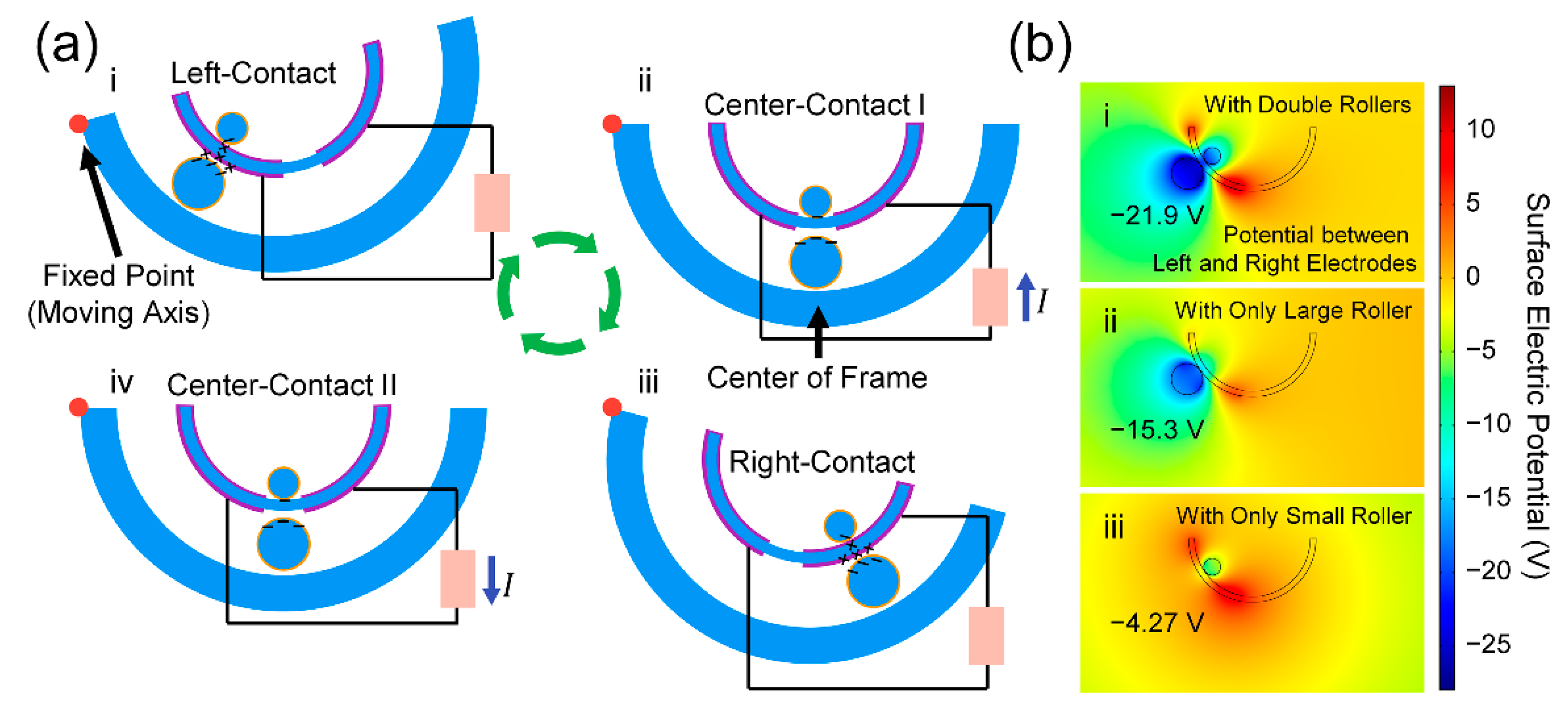
:
1. Introduction
2. Materials and Methods
2.1. Fabrication of the DR-TENG
2.2. Surface Characterization of the DR-TENG Device
2.3. FEM Analysis
2.4. Measurement of the Electrical Output from the DR-TENG
2.5. Setting Up a Water Wave Test
3. Results
3.1. Structure and Operating Mechanism of the DR-TENG
3.2. Structure and Operating Mechanism of the DR-TENG
3.3. Electrical Output Characteristics of the DR-TENG
3.4. Applications of the DR-TENG
4. Discussion
Supplementary Materials
Author Contributions
Funding
Conflicts of Interest
References
- Jin, Z.; Charlock, T.P.; Smith, W.L.; Rutledge, K. A Parameterization of Ocean Surface Albedo. Geophys. Res. Lett. 2004, 31, L22301. [Google Scholar] [CrossRef]
- Höök, M.; Tang, X. Depletion of Fossil Fuels and Anthropogenic Climate Change-A Review. Energy Policy 2013, 52, 797–809. [Google Scholar] [CrossRef] [Green Version]
- Chiari, L.; Zecca, A. Constraints of Fossil Fuels Depletion on Global Warming Projections. Energy Policy 2011, 39, 5026–5034. [Google Scholar] [CrossRef]
- Guler, U.; Sendi, M.S.E.; Ghovanloo, M. A Dual-Mode Passive Rectifier for Wide-Range Input Power Flow. In Proceedings of the 2017 IEEE 60th International Midwest Symposium on Circuits and Systems (MWSCAS), Medford, MA, USA, 6 August 2017; pp. 1376–1379. [Google Scholar]
- Batten, W.M.J.; Bahaj, A.S.; Molland, A.F.; Chaplin, J.R. Experimentally Validated Numerical Method for the Hydrodynamic Design of Horizontal Axis Tidal Turbines. Ocean. Eng. 2007, 34, 1013–1020. [Google Scholar] [CrossRef]
- Myers, L.E.; Bahaj, A.S. Experimental Analysis of the Flow Field around Horizontal Axis Tidal Turbines by Use of Scale Mesh Disk Rotor Simulators. Ocean. Eng. 2010, 37, 218–227. [Google Scholar] [CrossRef]
- Viviano, A.; Naty, S.; Foti, E.; Bruce, T.; Allsop, W.; Vicinanza, D. Large-Scale Experiments on the Behaviour of a Generalised Oscillating Water Column under Random Waves. Renew. Energy 2016, 99, 875–887. [Google Scholar] [CrossRef] [Green Version]
- Guarnieri, M. The Development of Ac Rotary Machines. IEEE Ind. Electron. Mag. 2018, 12, 28–32. [Google Scholar] [CrossRef]
- Träsch, M.; Déporte, A.; Delacroix, S.; Drevet, J.B.; Gaurier, B.; Germain, G. Power Estimates of an Undulating Membrane Tidal Energy Converter. Ocean. Eng. 2018, 148, 115–124. [Google Scholar] [CrossRef] [Green Version]
- Fan, F.R.; Tian, Z.Q.; Wang, Z.L. Flexible Triboelectric Generator. Nano Energy 2012, 1, 328–334. [Google Scholar] [CrossRef]
- Wang, Z.L.; Chen, J.; Lin, L. Progress in Triboelectric Nanogenerators as a New Energy Technology and Self-Powered Sensors. Energy Environ. Sci. 2015, 8, 2250–2282. [Google Scholar] [CrossRef]
- Wu, C.; Wang, A.C.; Ding, W.; Guo, H.; Wang, Z.L. Triboelectric Nanogenerator: A Foundation of the Energy for the New Era. Adv. Energy Mater. 2019, 9, 1802906. [Google Scholar] [CrossRef]
- Kim, D.; Oh, Y.; Hwang, B.W.; Jeon, S.B.; Park, S.J.; Choi, Y.K. Triboelectric Nanogenerator Based on the Internal Motion of Powder with a Package Structure Design. ACS Nano 2016, 10, 1017–1024. [Google Scholar] [CrossRef]
- Guo, T.; Liu, G.; Pang, Y.; Wu, B.; Xi, F.; Zhao, J.; Bu, T.; Fu, X.; Li, X.; Zhang, C.; et al. Compressible Hexagonal-Structured Triboelectric Nanogenerators for Harvesting Tire Rotation Energy. Extrem. Mech. Lett. 2018, 18, 1–8. [Google Scholar] [CrossRef]
- Kim, D.; Tcho, I.W.; Choi, Y.K. Triboelectric Nanogenerator Based on Rolling Motion of Beads for Harvesting Wind Energy as Active Wind Speed Sensor. Nano Energy 2018, 52, 256–263. [Google Scholar] [CrossRef]
- Kim, I.; Chae, Y.; Jo, S.; Kim, D. Levitating Oscillator-Based Triboelectric Nanogenerator for Harvesting from Rotational Motion and Sensing Seismic Oscillation. Nano Energy 2020, 72, 104674. [Google Scholar] [CrossRef]
- Gao, S.; Zhu, Y.; Chen, Y.; Tian, M.; Yang, Y.; Jiang, T.; Wang, Z.L. Self-Power Electroreduction of N2 into NH3 by 3D Printed Triboelectric Nanogenerators. Mater. Today 2019, 28, 17–24. [Google Scholar] [CrossRef]
- Tian, M.; Zhang, D.; Wang, M.; Zhu, Y.; Chen, C.; Chen, Y.; Jiang, T.; Gao, S. Engineering Flexible 3D Printed Triboelectric Nanogenerator to Self-Power Electro-Fenton Degradation of Pollutants. Nano Energy 2020, 74, 104908. [Google Scholar] [CrossRef]
- Peng, X.; Dong, K.; Ye, C.; Jiang, Y.; Zhai, S.; Cheng, R.; Liu, D.; Gao, X.; Wang, J.; Wang, Z.L. A Breathable, Biodegradable, Antibacterial, and Self-Powered Electronic Skin Based on All-Nanofiber Triboelectric Nanogenerators. Sci. Adv. 2020, 6, eaba9624. [Google Scholar] [CrossRef]
- Dong, K.; Peng, X.; Wang, Z.L. Fiber/Fabric-Based Piezoelectric and Triboelectric Nanogenerators for Flexible/Stretchable and Wearable Electronics and Artificial Intelligence. Adv. Mater. 2020, 32, 1902549. [Google Scholar] [CrossRef]
- Dong, K.; Peng, X.; An, J.; Wang, A.C.; Luo, J.; Sun, B.; Wang, J.; Wang, Z.L. Shape Adaptable and Highly Resilient 3D Braided Triboelectric Nanogenerators as E-Textiles for Power and Sensing. Nat. Commun. 2020, 11, 2868. [Google Scholar] [CrossRef] [PubMed]
- Peng, X.; Dong, K.; Wu, Z.; Wang, J.; Wang, Z.L. A Review on Emerging Biodegradable Polymers for Environmentally Benign Transient Electronic Skins. J. Mater. Sci. 2021, 56, 16765–16789. [Google Scholar] [CrossRef]
- Rodrigues, C.; Kumar, M.; Proenca, M.P.; Gutierrez, J.; Melo, R.; Pereira, A.; Ventura, J. Triboelectric Energy Harvesting in Harsh Conditions: Temperature and Pressure Effects in Methane and Crude Oil Environments. Nano Energy 2020, 72, 104682. [Google Scholar] [CrossRef]
- Kim, I.; Roh, H.; Yu, J.; Jayababu, N.; Kim, D. Boron Nitride Nanotube-Based Contact Electrification-Assisted Piezoelectric Nanogenerator as a Kinematic Sensor for Detecting the Flexion–Extension Motion of a Robot Finger. ACS Energy Lett. 2020, 5, 1577–1585. [Google Scholar] [CrossRef]
- Seol, M.L.; Han, J.W.; Moon, D.I.; Meyyappan, M. Triboelectric Nanogenerator for Mars Environment. Nano Energy 2017, 39, 238–244. [Google Scholar] [CrossRef]
- Liu, L.; Shi, Q.; Ho, J.S.; Lee, C. Study of Thin Film Blue Energy Harvester Based on Triboelectric Nanogenerator and Seashore IoT Applications. Nano Energy 2019, 66, 104167. [Google Scholar] [CrossRef]
- Chen, X.; Gao, L.; Chen, J.; Lu, S.; Zhou, H.; Wang, T.; Wang, A.; Zhang, Z.; Guo, S.; Mu, X.; et al. A Chaotic Pendulum Triboelectric-Electromagnetic Hybridized Nanogenerator for Wave Energy Scavenging and Self-Powered Wireless Sensing System. Nano Energy 2020, 69, 104440. [Google Scholar] [CrossRef]
- Chen, J.; Yang, J.; Li, Z.; Fan, X.; Zi, Y.; Jing, Q.; Guo, H.; Wen, Z.; Pradel, K.C.; Niu, S.; et al. Networks of Triboelectric Nanogenerators for Harvesting Water Wave Energy: A Potential Approach toward Blue Energy. ACS Nano 2015, 9, 3324–3331. [Google Scholar] [CrossRef] [PubMed]
- Liang, X.; Jiang, T.; Feng, Y.; Lu, P.; An, J.; Wang, Z.L. Triboelectric Nanogenerator Network Integrated with Charge Excitation Circuit for Effective Water Wave Energy Harvesting. Adv. Energy Mater. 2020, 10, 2002123. [Google Scholar] [CrossRef]
- Liang, X.; Jiang, T.; Liu, G.; Feng, Y.; Zhang, C.; Wang, Z.L. Spherical Triboelectric Nanogenerator Integrated with Power Management Module for Harvesting Multidirectional Water Wave Energy. Energy Environ. Sci. 2020, 13, 277–285. [Google Scholar] [CrossRef]
- Liu, G.; Guo, H.; Xu, S.; Hu, C.; Wang, Z.L. Oblate Spheroidal Triboelectric Nanogenerator for All-Weather Blue Energy Harvesting. Adv. Energy Mater. 2019, 9, 1900801. [Google Scholar] [CrossRef]
- Wang, X.; Niu, S.; Yin, Y.; Yi, F.; You, Z.; Wang, Z.L. Triboelectric Nanogenerator Based on Fully Enclosed Rolling Spherical Structure for Harvesting Low-Frequency Water Wave Energy. Adv. Energy Mater. 2015, 5, 1501467. [Google Scholar] [CrossRef]
- Gao, L.; Lu, S.; Xie, W.; Chen, X.; Wu, L.; Wang, T.; Wang, A.; Yue, C.; Tong, D.; Lei, W.; et al. A Self-Powered and Self-Functional Tracking System Based on Triboelectric-Electromagnetic Hybridized Blue Energy Harvesting Module. Nano Energy 2020, 72, 104684. [Google Scholar] [CrossRef]
- Xie, Z.; Dong, J.; Li, Y.; Gu, L.; Song, B.; Cheng, T.; Wang, Z.L. Triboelectric Rotational Speed Sensor Integrated into a Bearing: A Solid Step to Industrial Application. Extrem. Mech. Lett. 2020, 34, 100595. [Google Scholar] [CrossRef]
- Yang, W.; Gao, Q.; Xia, X.; Zhang, X.; Lu, X.; Yang, S.; Cheng, T.; Wang, Z.L. Travel Switch Integrated Mechanical Regulation Triboelectric Nanogenerator with Linear–Rotational Motion Transformation Mechanism. Extrem. Mech. Lett. 2020, 37, 100718. [Google Scholar] [CrossRef]
- Saadatnia, Z.; Asadi, E.; Askari, H.; Esmailzadeh, E.; Naguib, H.E. A Heaving Point Absorber-Based Triboelectric-Electromagnetic Wave Energy Harvester: An Efficient Approach toward Blue Energy. Int. J. Energy Res. 2018, 42, 2431–2447. [Google Scholar] [CrossRef]
- Xu, M.; Zhao, T.; Wang, C.; Zhang, S.L.; Li, Z.; Pan, X.; Wang, Z.L. High Power Density Tower-like Triboelectric Nanogenerator for Harvesting Arbitrary Directional Water Wave Energy. ACS Nano 2019, 13, 1932–1939. [Google Scholar] [CrossRef]
- Hao, C.; He, J.; Zhai, C.; Jia, W.; Song, L.; Cho, J.; Chou, X.; Xue, C. Two-Dimensional Triboelectric-Electromagnetic Hybrid Nanogenerator for Wave Energy Harvesting. Nano Energy 2019, 58, 147–157. [Google Scholar] [CrossRef]
- Wang, X.; Wen, Z.; Guo, H.; Wu, C.; He, X.; Lin, L.; Cao, X.; Wang, Z.L. Fully Packaged Blue Energy Harvester by Hybridizing a Rolling Triboelectric Nanogenerator and an Electromagnetic Generator. ACS Nano 2016, 10, 11369–11376. [Google Scholar] [CrossRef]
- Wu, Z.; Guo, H.; Ding, W.; Wang, Y.C.; Zhang, L.; Wang, Z.L. A Hybridized Triboelectric-Electromagnetic Water Wave Energy Harvester Based on a Magnetic Sphere. ACS Nano 2019, 13, 2349–2356. [Google Scholar] [CrossRef]
- Ahmed, A.; Saadatnia, Z.; Hassan, I.; Zi, Y.; Xi, Y.; He, X.; Zu, J.; Wang, Z.L. Self-Powered Wireless Sensor Node Enabled by a Duck-Shaped Triboelectric Nanogenerator for Harvesting Water Wave Energy. Adv. Energy Mater. 2017, 7, 1601705. [Google Scholar] [CrossRef]
- Gooding, D.M.; Kaufman, G.K. Tribocharging and the Triboelectric Series. In Encyclopedia of Inorganic and Bioinorganic Chemistry; John Wiley & Sons, Ltd.: Hoboken, NJ, USA, 2011; pp. 1–14. [Google Scholar]
- Niu, S.; Liu, Y.; Chen, X.; Wang, S.; Zhou, Y.S.; Lin, L.; Xie, Y.; Wang, Z.L. Theory of Freestanding Triboelectric-Layer-Based Nanogenerators. Nano Energy 2015, 12, 760–774. [Google Scholar] [CrossRef] [Green Version]


Publisher’s Note: MDPI stays neutral with regard to jurisdictional claims in published maps and institutional affiliations. |
© 2021 by the authors. Licensee MDPI, Basel, Switzerland. This article is an open access article distributed under the terms and conditions of the Creative Commons Attribution (CC BY) license (https://creativecommons.org/licenses/by/4.0/).
Share and Cite
Kim, I.; Kim, D. 3D Printed Double Roller-Based Triboelectric Nanogenerator for Blue Energy Harvesting. Micromachines 2021, 12, 1089. https://doi.org/10.3390/mi12091089
Kim I, Kim D. 3D Printed Double Roller-Based Triboelectric Nanogenerator for Blue Energy Harvesting. Micromachines. 2021; 12(9):1089. https://doi.org/10.3390/mi12091089
Chicago/Turabian StyleKim, Inkyum, and Daewon Kim. 2021. "3D Printed Double Roller-Based Triboelectric Nanogenerator for Blue Energy Harvesting" Micromachines 12, no. 9: 1089. https://doi.org/10.3390/mi12091089
APA StyleKim, I., & Kim, D. (2021). 3D Printed Double Roller-Based Triboelectric Nanogenerator for Blue Energy Harvesting. Micromachines, 12(9), 1089. https://doi.org/10.3390/mi12091089