
Ultrawideband Antennas: Growth and Evolution


Abstract
:1. Introduction
2. UWB Antenna Technology
3. Progress/Emergence of Design of UWB Antenna

| Reference No. | Size (mm2) | Gain (dBi) | Efficiency | Advantage/Disadvantage | Reason for UWB Performance | Design Methodology | Operating Frequency Range (GHz) |
|---|---|---|---|---|---|---|---|
| [48] | - | - | - | Advantage: Good impedance matching and compact in size Disadvantage: Absorber treatment is required in E and H planes to achieve desired performance | Bowtie TEM horn | Genetic algorithm | 3.1–10.6 |
| [50] | - | - | Advantage: High bandwidth Stable radiation pattern Disadvantage: Large size | introduction of a bevel | Cutting slots in each side of the planar element | 0.8–10.5 | |
| [51] | - | 20–100 | Advantage: Elliptical polarization and near hemispherical coverage Disadvantage: Low efficiency at lower frequencies | A genetic antenna consisting of a set of wires connected in series and with impedance loads | genetic antenna | 0.3–15 | |
| [52] | - | - | Advantage: Important design characteristics can be measured using this FTDT model Disadvantage: Complex antenna | planar bowtie dipole with the feed point being raised off the ground | FDTD technique | 3.1–10.6 | |
| [55] | 12.5 | - | Advantage: Good group delay Disadvantage: Unstable radiation pattern | The broadband microstrip line to the slot line transition causes a large impedance bandwidth. | Tapered slot | 3.1–10.6 | |
| [56] | 8 | - | Advantage: Good frequency characteristics in the UWB range Disadvantage: Poor polarization | Circular disc monopole fed by microstrip line | Use of the feed gap, the width of the ground plane, and the size of the disc. | 2.6–10.1 | |
| [57] | 11 | - | Advantage: Improves bandwidth of TEM horn antenna Disadvantage: High cross-polarization | TEM horn antenna with exponential tapering with a balun of microstrip type | Use of linearly tapered and exponentially tapered structure | 0.6–15.7 | |
| [59] | 8 | - | Advantage: Excellent polarization and good impedance bandwidth Disadvantage: Gain decreases from 6 GHz to 10 GHz | Magnetic coupling of symmetrical sectoral antennas of loop shape | Two Sectors | 2–16 | |
| [60] | 7 | - | Advantage: Easily fabricated using the single metal plate and Cost-effective Disadvantage: Large size | Trident-Shaped Feeding Strip | Combination of square planar monopole antenna with a trident-shaped feeding strip | 1.4–11.4 | |
| [61] | 1000 | 8 | - | Advantage: It doesn’t need an anechoic chamber for measurement Sensitivity to noise is low Disadvantage: Efficiency is low | Use of conducting wire antenna as a pair of scissors | scissors antenna consists of conducting wires | 0.2–4 |
| [62] | 6 | - | Advantage: Uniform radiation pattern and less distortion in the baseband signal Disadvantage: The tradeoff between antenna performance and miniaturization | The tapered-slot feed acts transform the impedance and directs the maximum radiation from the slot line to the radiating slot | Tapered slot | 3.1–10.6 | |
| [63] | 7 | - | Advantage: Omnidirectional radiation pattern Disadvantage: The time-domain analysis is not performed | CPW fed with a U-shaped tuning stub and elliptical slot | Elliptical slot with U shaped stub | 3.1–10.6 | |
| [64] | 12 | - | Advantage: High gain Disadvantage: Large size | Double exponential tapered slot on LCP gives end-fire radiation in UWB range of frequency | Double exponential tapered slot | 3.1–10.6 | |
| [65] | - | - | Advantage: Stable radiation pattern up to 6 GHz Disadvantage: Pattern not stable at higher frequencies | planar rectangular monopole antenna with a sleeved transmission line with the displaced feed point | sleeved transmission line- fed rectangular planar disc monopole antenna with a small ground plane | 0.5–9.0 | |
| [66] | 2.2 | - | Advantage: Suitable for mm-wave applications Disadvantage: Less gain | Resonators of varying lengths are added along the feedline. | Stepped slots | 6–22 | |
| [67] | 7 | 80 | Advantage: Large bandwidth and low pulse distortion Disadvantage: Large size and complex structure | A tapered loop is formed from the CPW to CPS to increase the operating bandwidth | Circular tapered slot | 3.1–10.6 | |
| [68] | 6 | - | Advantage: Impedance bandwidth of 144.8% and stable radiation pattern Disadvantage: Large size | A circular slot with a new moon-shaped strip connected to the feed line causes a wide bandwidth. This is created to stabilize the radiation pattern at higher frequencies. | Circular slot with moon-shaped strip | 2.4–11 | |
| [69] | 3.8 | - | Advantage: High efficiency and good omnidirectional radiation pattern Disadvantage: for 3.1 to 4 GHz | Beveling the bottom border of planar monopole antenna | Slot cut in the ground plane | 3.1–12 | |
| [70] | 18 | - | Advantage: Good gain and directivity. Negligible cross-polarization Disadvantage: Weak phase dispersivity | Slot etching on the ground plane with a central point feed | leaky slot line | 4–40 | |
| [71] | 1.54 | - | Advantage: Simple structure and stable radiation pattern Disadvantage: Less gain and large size | The curves of the antenna edge by a binomial function which gives the wider impedance bandwidth | Use of a binomial function | 2.5–10.9 | |
| [72] | 251.32 | 7 | - | Advantage: Constant high gain and good transient response Disadvantage: Complex design | Biconical dipole with metallic reflector | Tapered stripline balun | 3–20 |
| [73] | 8.2 | - | Advantage: Minimum ringing and dispersion of pulse in the time domain Disadvantage: Large dimension | Elliptical monopole antenna | Elliptical monopole antenna | 12–12.6 | |
| [74] | 9.9 | - | Advantage: Good gain Disadvantage: The radiation pattern is moderate. | Suspended (Plate antenna) structure | It consists of four top plates connected to a bottom plate using four vertical strips. | 3.1–4.8 | |
| [75] | 5.2 | - | Advantage: Simple design, cost-effective, and mechanically robust Disadvantage: Large size | Suspended plate antenna with the shorting wall together with the L-probe feed | Parasitic L-shaped plate | 3–12 | |
| [76] | 4 | - | Advantage: Omnidirectional radiation patter with low cross-polarization Disadvantage: High insertion loss below 5 GHz and limited gain therein | The planar monopole has strong vertical currents, which leads to large impedance bandwidth. A triangular feeding strip is used. | Rectangular monopole with an equal-width ground plane | 2.7–16.2 | |
| [77] | 4.13 | - | Advantage: Low VSWR, stable gain and linear phase Disadvantage: There is a reduction in radiation efficiency due to an increase in input impedance in the mid UWB band. | There are electric and magnetic radiators. Energy stored in matching stubs is radiated because of the CPW-slot line transition. | Two rectangular slots | 3.1–10.6 | |
| [78] | 4 | - | Advantage: Simple feeding structure and good bandwidth Disadvantage: Large size | The polygonal slot results in bandwidth enhancement | Polygonal slot | 1.8–5.9 | |
| [79] | 5.9 | - | Advantage: Small size with impedance bandwidth of 122% Disadvantage: The radiation pattern is quite unstable. | Asymmetrical beveled rectangular patch with a U slot causes enhancement in bandwidth | Asymmetrical rectangular patch with U shaped slot | 2.9–12.1 |
4. The Emergence of UWB Notch Antenna
- Modifications on the radiator.
- Modifications on the ground plane or signal line.
- Integrated filter techniques.
- Metamaterial-inspired resonators.
5. Frequency Reconfigurable UWB Notch Antenna
5.1. Principle of Antenna Reconfiguration
5.2. Frequency Reconfigurable Antennas
6. Conclusions
Author Contributions
Funding
Institutional Review Board Statement
Informed Consent Statement
Data Availability Statement
Conflicts of Interest
References
- Federal Communications Commission (FCC). Revision of Part 15 of The Commission’s Rules Regarding Ultra-Wideband Transmission Systems. In First Report and Order; ET Docket: Washington, DC, USA, 2002; pp. 98–153. [Google Scholar]
- Moccia, A.; Vetrella, S.; Bertoni, R. Mission analysis and design of a bistatic synthetic aperture radar on board a small satellite. Acta Astronaut. 2000, 47, 819–829. [Google Scholar] [CrossRef]
- Rush, J. Current issues in the use of the global positioning system aboard satellites. Acta Astronaut. 2000, 47, 377–387. [Google Scholar] [CrossRef]
- Wallinga, G.; Rothwell, E.; Chen, K.-M.; Nyquist, D. Enhanced detection of a target in a sea clutter environment using a stepped, ultra-wideband signal and E-pulse cancellation. IEEE Trans. Antennas Propag. 2001, 49, 1166–1173. [Google Scholar] [CrossRef]
- Remondo, D.; Niemegeers, I.G. Ad hoc networking in future wireless communications. Comput. Commun. 2003, 26, 36–40. [Google Scholar] [CrossRef]
- Walke, B.H.; Kumar, V. Spectrum issues and new air interfaces. Comput. Commun. 2003, 26, 53–63. [Google Scholar] [CrossRef]
- Tafazolli, R. (Ed.) Technologies for the Wireless Future; Wireless World Research Forum (WWRF); John Wiley & Sons: Hoboken, NJ, USA, 2006. [Google Scholar]
- Gschwendtner, E.; Wiesbeck, W. Ultra-broadband car antennas for communications and navigation applications. IEEE Trans. Antennas Propag. 2003, 51, 2020–2027. [Google Scholar] [CrossRef]
- Chen, C.-C.; Rao, K.R.; Lee, R. A new ultrawide-bandwidth dielectric-rod antenna for ground-penetrating radar applications. IEEE Trans. Antennas Propag. 2003, 51, 371–377. [Google Scholar] [CrossRef]
- Kim, K.; Scott, W. Design of a resistively loaded vee dipole for ultrawide-band ground-penetrating Radar applications. IEEE Trans. Antennas Propag. 2005, 53, 2525–2532. [Google Scholar] [CrossRef]
- Giuliano, R.; Guidoni, G.; Habib, I.; Mazzenga, F. Coexistence of an ultrawideband spread spectrum system with fixed wireless access systems. Comput. Netw. 2004, 44, 583–598. [Google Scholar] [CrossRef]
- Lopez, J., Jr.; Raines, R.A.; Temple, M.A.; Baldwin, R.O.; Stephens, J.P., Sr. An investigation on the effects of emerging 4G transmissions on 3G networks. Omega 2007, 35, 706–714. [Google Scholar] [CrossRef]
- Turkmen, M.; Yalduz, H. Design and Performance Analysis of a Flexible UWB Wearable Textile Antenna on Jeans Substrate. Int. J. Inf. Electron. Eng. 2018, 8, 15–18. [Google Scholar] [CrossRef] [Green Version]
- Mersani, A.; Osman, L.; Ribero, J.-M. Flexible UWB AMC antenna for early stage skin cancer identification. Prog. Electromagn. Res. M 2019, 80, 71–81. [Google Scholar] [CrossRef] [Green Version]
- Simorangkir, R.B.; Kiourti, A.; Esselle, K.P. UWB Wearable Antenna with a Full Ground Plane Based on PDMS-Embedded Conductive Fabric. IEEE Antennas Wirel. Propag. Lett. 2018, 17, 493–496. [Google Scholar] [CrossRef]
- Negi, D.; Khanna, R.; Kaur, J. Design and performance analysis of a conformal CPW fed wideband antenna with Mu-Negative metamaterial for wearable applications. Int. J. Microw. Wirel. Technol. 2019, 11, 806–820. [Google Scholar] [CrossRef]
- Lin, X.; Chen, Y.; Gong, Z.; Seet, B.-C.; Huang, L.; Lu, Y. Ultrawideband Textile Antenna for Wearable Microwave Medical Imaging Applications. IEEE Trans. Antennas Propag. 2020, 68, 4238–4249. [Google Scholar] [CrossRef]
- Klemm, M.; Troester, G. Textile UWB Antennas for Wireless Body Area Networks. IEEE Trans. Antennas Propag. 2006, 54, 3192–3197. [Google Scholar] [CrossRef] [Green Version]
- Kumar, V.; Gupta, B. On-body measurements of SS-UWB patch antenna for WBAN applications. AEU-Int. J. Electron. Commun. 2016, 70, 668–675. [Google Scholar] [CrossRef]
- Elobaid, H.A.E.; Rahim, S.K.A.; Himdi, M.; Castel, X.; Kasgari, M.A. A Transparent and Flexible Polymer-Fabric Tissue UWB Antenna for Future Wireless Networks. IEEE Antennas Wirel. Propag. Lett. 2016, 16, 1333–1336. [Google Scholar] [CrossRef]
- Yalduz, H.; Tabaru, T.E.; Kilic, V.T.; Turkmen, M. Design and analysis of low profile and low SAR full-textile UWB wearable antenna with metamaterial for WBAN applications. AEU-Int. J. Electron. Commun. 2020, 126, 153465. [Google Scholar] [CrossRef]
- Hossain, M.J.; Faruque, M.R.I.; Islam, M.M.; Islam, M.T.; Rahman, M.A. Bird face microstrip printed monopole antenna design for ultra wide band applications. Frequenz 2016, 70, 473–478. [Google Scholar] [CrossRef]
- Rajagopalan, A.; Gupta, G.; Konanur, A.S.; Hughes, B.; Lazzi, G. Increasing Channel Capacity of an Ultrawideband MIMO System Using Vector Antennas. IEEE Trans. Antennas Propag. 2007, 55, 2880–2887. [Google Scholar] [CrossRef]
- Su, S.-W.; Chou, J.-H.; Wong, K.-L. Internal Ultrawideband Monopole Antenna for Wireless USB Dongle Applications. IEEE Trans. Antennas Propag. 2007, 55, 1180–1183. [Google Scholar] [CrossRef]
- Farwell, M.; Ross, J.; Luttrell, R.; Cohen, D.; Chin, W.; Dogaru, T. Sense through the wall system development and design considerations. J. Frankl. Inst. 2008, 345, 570–591. [Google Scholar] [CrossRef]
- Narayanan, R.M. Through-wall radar imaging using UWB noise waveforms. J. Frankl. Inst. 2008, 345, 659–678. [Google Scholar] [CrossRef]
- Liang, J.; Liang, Q. Sense-Through-Foliage target detection using UWB radar sensor networks. Pattern Recognit. Lett. 2010, 31, 1412–1421. [Google Scholar] [CrossRef]
- He, X.; Jiang, T. Target identification in foliage environment using UWB radar with hybrid wavelet—ICA and SVM method. Phys. Commun. 2014, 13, 197–204. [Google Scholar] [CrossRef]
- Li, X.; Liang, Q.; Lau, F.C. Sense-through-wall human detection using the UWB radar with sparse SVD. Phys. Commun. 2014, 13, 260–266. [Google Scholar] [CrossRef]
- Zhang, Z.; Langer, J.-C.; Li, K.; Iskander, M. Design of Ultrawideband Mobile Phone Stubby Antenna (824 MHz-6 GHz). IEEE Trans. Antennas Propag. 2008, 56, 2107–2111. [Google Scholar] [CrossRef]
- José, M.; Castro-Lopez, R.; Morgado, A.; Becerra-Alvarez, E.C.; del Rio, R.; Fernandez, F.V.; Perez-Verdu, B. Adaptive CMOS analog circuits for 4G mobile terminals—Review and state-of-the-art survey. Microelectron. J. 2009, 40, 156–176. [Google Scholar]
- Chehri, A.; Fortier, P.; Tardif, P.M. UWB-based sensor networks for localization in mining environments. Ad Hoc Netw. 2009, 7, 987–1000. [Google Scholar] [CrossRef]
- Ahmed, B.T.; Campos, J.L.M.; Ruiz-Cruz, J.A. Impact of Ultra Wide Band emission on WiMAX systems at 2.5 and 3.5 GHz. Comput. Netw. 2010, 54, 1573–1583. [Google Scholar] [CrossRef]
- Van Der Linde, E.; Hancke, G. An investigation of Bluetooth mergence with Ultra Wideband. Ad Hoc Netw. 2011, 9, 852–863. [Google Scholar] [CrossRef] [Green Version]
- Fuchs, C.; Aschenbruck, N.; Martini, P.; Wieneke, M. Indoor tracking for mission critical scenarios: A survey. Pervasive Mob. Comput. 2011, 7, 1–15. [Google Scholar] [CrossRef]
- Cheng, T.; Venugopal, M.; Teizer, J.; Vela, P.A. Performance evaluation of ultra wideband technology for construction resource location tracking in harsh environments. Autom. Constr. 2011, 20, 1173–1184. [Google Scholar] [CrossRef]
- Chunming, W.; Guoliang, D. The Study of UWB Radar Life-Detection for Searching Human Subjects. Energy Procedia 2012, 17, 1028–1033. [Google Scholar] [CrossRef] [Green Version]
- Sun, J.; Li, M. Life detection and location methods using UWB impulse radar in a coal mine. Min. Sci. Technol. 2011, 21, 687–691. [Google Scholar] [CrossRef]
- Liu, L.; Liu, Z.; Xie, H.; Barrowes, B.; Bagtzoglou, A.C. Numerical simulation of UWB impulse radar vital sign detection at an earthquake disaster site. Ad Hoc Netw. 2014, 13, 34–41. [Google Scholar] [CrossRef]
- Rabbani, M.S.; Ghafouri-Shiraz, H. Accurate remote vital sign monitoring with 10 GHz ultra-wide patch antenna array. AEU-Int. J. Electron. Commun. 2017, 77, 36–42. [Google Scholar] [CrossRef]
- Imran, A.I.; Elwi, T.A. A cylindrical wideband slotted patch antenna loaded with Frequency Selective Surface for MRI applications. Eng. Sci. Technol. Int. J. 2017, 20, 990–996. [Google Scholar] [CrossRef]
- Srikanth, B.S.; Gurung, S.B.; Manu, S.; Gowthami, G.N.; Ali, T.; Pathan, S. A slotted UWB monopole antenna with truncated ground plane for breast cancer detection. Alex. Eng. J. 2020, 59, 3767–3780. [Google Scholar] [CrossRef]
- Moosazadeh, M.; Kharkovsky, S.; Case, J.T.; Samali, B. Miniaturized UWB Antipodal Vivaldi Antenna and Its Application for Detection of Void Inside Concrete Specimens. IEEE Antennas Wirel. Propag. Lett. 2016, 16, 1317–1320. [Google Scholar] [CrossRef]
- Ghendir, S.; Sbaa, S.; Al-Sherbaz, A.; Ajgou, R.; Chemsa, A. Towards 5G wireless systems: A modified Rake receiver for UWB indoor multipath channels. Phys. Commun. 2019, 35, 100715. [Google Scholar] [CrossRef]
- Akbarpour, A.; Chamaani, S. Ultrawideband Circularly Polarized Antenna for Near-Field SAR Imaging Applications. IEEE Trans. Antennas Propag. 2020, 68, 4218–4228. [Google Scholar] [CrossRef]
- Maitre, J.; Bouchard, K.; Bertuglia, C.; Gaboury, S. Recognizing activities of daily living from UWB radars and deep learning. Expert Syst. Appl. 2021, 164, 113994. [Google Scholar] [CrossRef]
- Hirt, W. Ultra-wideband radio technology: Overview and future research. Comput. Commun. 2003, 26, 46–52. [Google Scholar] [CrossRef]
- Chung, L.; Chang, T.; Burnside, W. An ultrawide-bandwidth tapered resistive TEM horn antenna. IEEE Trans. Antennas Propag. 2000, 48, 1848–1857. [Google Scholar] [CrossRef]
- Ghorbani, K.; Waterhouse, R. Ultrabroadband printed (ubp) antenna. IEEE Trans. Antennas Propag. 2002, 50, 1697–1705. [Google Scholar] [CrossRef]
- Ammann, M.; Chen, Z.N. A wide-band shorted planar monopole with bevel. IEEE Trans. Antennas Propag. 2003, 51, 901–903. [Google Scholar] [CrossRef]
- Altshuler, E.; Linden, D. An Ultrawide-Band Impedance-Loaded Genetic Antenna. IEEE Trans. Antennas Propag. 2004, 52, 3147–3150. [Google Scholar] [CrossRef]
- Lee, K.-H.; Chen, C.-C.; Teixeira, F.; Lee, R. Modeling and Investigation of a Geometrically Complex UWB GPR Antenna Using FDTD. IEEE Trans. Antennas Propag. 2004, 52, 1983–1991. [Google Scholar] [CrossRef]
- Suh, S.-Y.; Stutzman, W.; Davis, W. A New Ultrawideband Printed Monopole Antenna: The Planar Inverted Cone Antenna (PICA). IEEE Trans. Antennas Propag. 2004, 52, 1361–1365. [Google Scholar] [CrossRef]
- Venkatarayalu, N.; Chen, C.-C.; Teixeira, F.; Lee, R. Numerical Modeling of Ultrawide-Band Dielectric Horn Antennas Using FDTD. IEEE Trans. Antennas Propag. 2004, 52, 1318–1323. [Google Scholar] [CrossRef]
- Ma, T.-G.; Jeng, S.-K. A printed dipole antenna with tapered slot feed for ultrawide-band applications. IEEE Trans. Antennas Propag. 2005, 53, 3833–3836. [Google Scholar] [CrossRef]
- Liang, J.; Chiau, C.C.; Chen, X.; Parini, C.G. Study of a printed circular disc monopole antenna for UWB systems. IEEE Trans. Antennas Propag. 2005, 53, 3500–3504. [Google Scholar] [CrossRef]
- Chung, K.; Pyun, S.; Choi, J. Design of an ultrawide-band TEM horn antenna with a microstrip-type balun. IEEE Trans. Antennas Propag. 2005, 53, 3410–3413. [Google Scholar] [CrossRef]
- Ying, C.; Zhang, Y. A planar antenna in LTCC for single-package ultrawide-band radio. IEEE Trans. Antennas Propag. 2005, 53, 3089–3093. [Google Scholar] [CrossRef]
- Behdad, N.; Sarabandi, K. A compact antenna for ultrawide-band applications. IEEE Trans. Antennas Propag. 2005, 53, 2185–2192. [Google Scholar] [CrossRef] [Green Version]
- Wong, K.-L.; Wu, C.-H.; Su, S.-W. Ultrawide-band square planar metal-plate monopole antenna with a trident-shaped feeding strip. IEEE Trans. Antennas Propag. 2005, 53, 1262–1269. [Google Scholar] [CrossRef]
- Andrieu, J.; Nouvet, S.; Bertrand, V.; Beillard, B.; Jecko, B. Transient characterization of a novel ultrawide-band antenna: The scissors antenna. IEEE Trans. Antennas Propag. 2005, 53, 1254–1261. [Google Scholar] [CrossRef]
- Ma, T.-G.; Jeng, S.-K. Planar miniature tapered-slot-fed annular slot antennas for ultrawide-band radios. IEEE Trans. Antennas Propag. 2005, 53, 1194–1202. [Google Scholar] [CrossRef]
- Li, P.; Liang, J.; Chen, X. Study of Printed Elliptical/Circular Slot Antennas for Ultrawideband Applications. IEEE Trans. Antennas Propag. 2006, 54, 1670–1675. [Google Scholar] [CrossRef]
- Thomas, K.; Lenin, N.; Sivaramakrishnan, R. Ultrawideband Planar Disc Monopole. IEEE Trans. Antennas Propag. 2006, 54, 1339–1341. [Google Scholar] [CrossRef]
- Nikolaou, S.; Ponchak, G.; Papapolymerou, J.; Tentzeris, M. Conformal Double Exponentially Tapered Slot Antenna (DETSA) on LCP for UWB Applications. IEEE Trans. Antennas Propag. 2006, 54, 1663–1669. [Google Scholar] [CrossRef]
- Rambabu, K.; Thiart, H.A.; Bornemann, J.; Yu, S.Y. Ultrawideband Printed-Circuit Antenna. IEEE Trans. Antennas Propag. 2006, 54, 3908–3911. [Google Scholar] [CrossRef]
- Mao, S.-G.; Chen, S.-L. Frequency- and Time-Domain Characterizations of Ultrawideband Tapered Loop Antennas. IEEE Trans. Antennas Propag. 2007, 55, 3698–3701. [Google Scholar] [CrossRef]
- Qu, S.-W.; Li, J.-L.; Chen, J.-X.; Xue, Q. Ultrawideband Strip-Loaded Circular Slot Antenna with Improved Radiation Patterns. IEEE Trans. Antennas Propag. 2007, 55, 3348–3353. [Google Scholar] [CrossRef]
- Ruvio, G.; Ammann, M. A Novel Wideband Semi-Planar Miniaturized Antenna. IEEE Trans. Antennas Propag. 2007, 55, 2679–2685. [Google Scholar] [CrossRef] [Green Version]
- Bruni, S.; Neto, A.; Marliani, F. The ultrawideband leaky lens antenna. IEEE Trans. Antennas Propag. 2007, 55, 2642–2653. [Google Scholar] [CrossRef]
- Ling, C.-W.; Lo, W.-H.; Yan, R.-H.; Chung, S.-J. Planar Binomial Curved Monopole Antennas for Ultrawideband Communication. IEEE Trans. Antennas Propag. 2007, 55, 2622–2624. [Google Scholar] [CrossRef]
- Blech, M.D.; Eibert, T.F. A Dipole Excited Ultrawideband Dielectric Rod Antenna with Reflector. IEEE Trans. Antennas Propag. 2007, 55, 1948–1954. [Google Scholar] [CrossRef]
- Ray, K.P.; Ranga, Y. Ultrawideband Printed Elliptical Monopole Antennas. IEEE Trans. Antennas Propag. 2007, 55, 1189–1192. [Google Scholar] [CrossRef]
- Ni Low, X.; Chen, Z.N.; Toh, W.K. Ultrawideband Suspended Plate Antenna with Enhanced Impedance and Radiation Performance. IEEE Trans. Antennas Propag. 2008, 56, 2490–2495. [Google Scholar] [CrossRef]
- See, T.S.P.; Chen, Z.N. An Electromagnetically Coupled UWB Plate Antenna. IEEE Trans. Antennas Propag. 2008, 56, 1476–1479. [Google Scholar] [CrossRef]
- Wu, Q.; Jin, R.; Geng, J.; Ding, M. Printed Omni-Directional UWB Monopole Antenna with Very Compact Size. IEEE Trans. Antennas Propag. 2008, 56, 896–899. [Google Scholar] [CrossRef]
- Kwon, D.-H.; Balzovsky, E.V.; Buyanov, Y.I.; Kim, Y.; Koshelev, V.I. Small Printed Combined Electric-Magnetic Type Ultrawideband Antenna with Directive Radiation Characteristics. IEEE Trans. Antennas Propag. 2008, 56, 237–241. [Google Scholar] [CrossRef]
- Eskandari, H.; Azarmanesh, M.N. Bandwidth enhancement of a printed wide-slot antenna with small slots. AEU-Int. J. Electron. Commun. 2009, 63, 896–900. [Google Scholar] [CrossRef]
- Liu, W.; Yin, Y.; Xu, W.; Zuo, S. Compact Open-Slot Antenna with Bandwidth Enhancement. IEEE Antennas Wirel. Propag. Lett. 2011, 10, 850–853. [Google Scholar] [CrossRef]
- Sowmya, G.A.; Kamath, A.; Keshava, A.; Kumar, O.P.; Vincent, S.; Ali, T. A circular monopole patch antenna loaded with inverted L-shaped stub for GPS application. Bull. Electr. Eng. Inform. 2020, 9, 1950–1957. [Google Scholar] [CrossRef]
- Saha, C.; Siddiqui, J.Y.; Antar, Y.M. Multifunctional Ultrawideband Antennas: Trends, Techniques and Applications; CRC Press: Boca Raton, FL, USA, 2019. [Google Scholar]
- Lin, Y.-C.; Hung, K.-J. Compact Ultrawideband Rectangular Aperture Antenna and Band-Notched Designs. IEEE Trans. Antennas Propag. 2006, 54, 3075–3081. [Google Scholar] [CrossRef]
- Kim, K.-H.; Park, S.-O. Analysis of the Small Band-Rejected Antenna with the Parasitic Strip for UWB. IEEE Trans. Antennas Propag. 2006, 54, 1688–1692. [Google Scholar] [CrossRef]
- Qiu, J.; Du, Z.; Lu, J.; Gong, K. A Planar Monopole Antenna Design with Band-Notched Characteristic. IEEE Trans. Antennas Propag. 2006, 54, 288–292. [Google Scholar] [CrossRef]
- Ma, T.-G.; Wu, S.-J. Ultrawideband Band-Notched Folded Strip Monopole Antenna. IEEE Trans. Antennas Propag. 2007, 55, 2473–2479. [Google Scholar] [CrossRef]
- Lui, W.-J.; Cheng, C.-H.; Zhu, H.-B. Improved Frequency Notched Ultrawideband Slot Antenna Using Square Ring Resonator. IEEE Trans. Antennas Propag. 2007, 55, 2445–2450. [Google Scholar] [CrossRef]
- Eshtiaghi, R.; Zaker, R.; Nouronia, J.; Ghobadi, C. UWB semi-elliptical printed monopole antenna with subband rejection filter. AEU-Int. J. Electron. Commun. 2010, 64, 133–141. [Google Scholar] [CrossRef]
- Azim, R.; Islam, M.T.; Misran, N. Compact Tapered-Shape Slot Antenna for UWB Applications. IEEE Antennas Wirel. Propag. Lett. 2011, 10, 1190–1193. [Google Scholar] [CrossRef]
- Agarwal, M.; Dhanoa, J.K.; Khandelwal, M.K. Ultrawide band two-port MIMO diversity antenna with triple notch bands, stable gain and suppressed mutual coupling. AEU-Int. J. Electron. Commun. 2020, 120, 153225. [Google Scholar] [CrossRef]
- Ghatak, R.; Karmakar, A.; Poddar, D. Hexagonal boundary Sierpinski carpet fractal shaped compact ultrawideband antenna with band rejection functionality. AEU-Int. J. Electron. Commun. 2013, 67, 250–255. [Google Scholar] [CrossRef]
- Roy, B.; Bhattacharya, A.; Chowdhury, S.; Bhattacharjee, A. Wideband Snowflake slot antenna using Koch iteration technique for wireless and C-band applications. AEU-Int. J. Electron. Commun. 2016, 70, 1467–1472. [Google Scholar] [CrossRef]
- Rajabloo, H.; Kooshki, V.A.; Oraizi, H. Compact microstrip fractal Koch slot antenna with ELC coupling load for triple band application. AEU-Int. J. Electron. Commun. 2017, 73, 144–149. [Google Scholar] [CrossRef]
- Zarrabi, F.B.; Mansouri, Z.; Gandji, N.P.; Kuhestani, H. Triple-notch UWB monopole antenna with fractal Koch and T-shaped stub. AEU-Int. J. Electron. Commun. 2016, 70, 64–69. [Google Scholar] [CrossRef]
- Sharma, M.; Awasthi, Y.K.; Singh, H.; Kumar, R.; Kumari, S. Compact printed high rejection triple band-notch UWB antenna with multiple wireless applications. Eng. Sci. Technol. Int. J. 2016, 19, 1626–1634. [Google Scholar] [CrossRef] [Green Version]
- Tang, Z.; Wu, X.; Zhan, J.; Hu, S.; Xi, Z.; Liu, Y. Compact UWB-MIMO Antenna with High Isolation and Triple Band-Notched Characteristics. IEEE Access 2019, 7, 19856–19865. [Google Scholar] [CrossRef]
- Kumar, A.; Ansari, A.Q.; Kanaujia, B.K.; Kishor, J.; Kumar, S. An ultra-compact two-port UWB-MIMO antenna with dual band-notched characteristics. AEU-Int. J. Electron. Commun. 2020, 114, 152997. [Google Scholar] [CrossRef]
- Cho, Y.J.; Kim, K.H.; Choi, D.H.; Lee, S.S.; Park, S.-O. A Miniature UWB Planar Monopole Antenna With 5-GHz Band-Rejection Filter and the Time-Domain Characteristics. IEEE Trans. Antennas Propag. 2006, 54, 1453–1460. [Google Scholar] [CrossRef]
- Ma, T.-G.; Tseng, C.-H. An Ultrawideband Coplanar Waveguide-Fed Tapered Ring Slot Antenna. IEEE Trans. Antennas Propag. 2006, 54, 1105–1110. [Google Scholar] [CrossRef]
- Hong, C.-Y.; Ling, C.-W.; Tarn, I.-Y.; Chung, S.-J. Design of a Planar Ultrawideband Antenna with a New Band-Notch Structure. IEEE Trans. Antennas Propag. 2007, 55, 3391–3397. [Google Scholar] [CrossRef]
- Zhang, J.-P.; Xu, Y.-S.; Wang, W.-D. Microstrip-Fed Semi-Elliptical Dipole Antennas for Ultrawideband Communications. IEEE Trans. Antennas Propag. 2008, 56, 241–244. [Google Scholar] [CrossRef]
- Soltani, S.; Azarmanesh, M.; Lotfi, P.; Dadashzadeh, G. Two novel very small monopole antennas having frequency band notch function using DGS for UWB application. AEU-Int. J. Electron. Commun. 2011, 65, 87–94. [Google Scholar] [CrossRef]
- Chitra, R.J.; Nagarajan, V. Double L-slot microstrip patch antenna array for WiMAX and WLAN applications. Comput. Electr. Eng. 2013, 39, 1026–1041. [Google Scholar] [CrossRef]
- Kang, L.; Li, H.; Wang, X.; Shi, X. Compact Offset Microstrip-Fed MIMO Antenna for Band-Notched UWB Applications. IEEE Antennas Wirel. Propag. Lett. 2015, 14, 1754–1757. [Google Scholar] [CrossRef]
- Huang, H.; Liu, Y.; Zhang, S.; Gong, S. Uniplanar Differentially Driven Ultrawideband Polarization Diversity Antenna with Band-Notched Characteristics. IEEE Antennas Wirel. Propag. Lett. 2014, 14, 563–566. [Google Scholar] [CrossRef]
- Bakariya, P.S.; Dwari, S.; Sarkar, M. Triple band notch UWB printed monopole antenna with enhanced bandwidth. AEU-Int. J. Electron. Commun. 2015, 69, 26–30. [Google Scholar] [CrossRef]
- Wang, Z.; Liu, J.; Yin, Y. Triple band-notched UWB antenna using novel asymmetrical resonators. AEU-Int. J. Electron. Commun. 2016, 70, 1630–1636. [Google Scholar] [CrossRef]
- Yadav, A.; Sethi, D.; Khanna, R. Slot loaded UWB antenna: Dual band notched characteristics. AEU-Int. J. Electron. Commun. 2016, 70, 331–335. [Google Scholar] [CrossRef]
- Peng, L.; Wen, B.-J.; Li, X.-F.; Jiang, X.; Li, S.-M. CPW Fed UWB Antenna by EBGs With Wide Rectangular Notched-Band. IEEE Access 2016, 4, 9545–9552. [Google Scholar] [CrossRef]
- Yang, Z.; Jingjian, H.; Weiwei, W.; Naichang, Y. An antipodal Vivaldi antenna with band-notched characteristics for ultra-wideband applications. AEU-Int. J. Electron. Commun. 2017, 76, 152–157. [Google Scholar] [CrossRef]
- Yang, B.; Qu, S. A compact integrated Bluetooth UWB dual-band notch antenna for automotive communications. AEU-Int. J. Electron. Commun. 2017, 80, 104–113. [Google Scholar] [CrossRef]
- Awad, N.M.; Abdelazeez, M.K. Multislot microstrip antenna for ultra-wide band applications. J. King Saud Univ.-Eng. Sci. 2018, 30, 38–45. [Google Scholar] [CrossRef] [Green Version]
- Mewara, H.S.; Deegwal, J.K.; Sharma, M.M. A slot resonators based quintuple band-notched Y-shaped planar monopole ultra-wideband antenna. AEU-Int. J. Electron. Commun. 2018, 83, 470–478. [Google Scholar] [CrossRef]
- Yadav, D.; Abegaonkar, M.P.; Koul, S.K.; Tiwari, V.; Bhatnagar, D. A compact dual band-notched UWB circular monopole antenna with parasitic resonators. AEU-Int. J. Electron. Commun. 2018, 84, 313–320. [Google Scholar] [CrossRef]
- Atallah, H.A.; Abdel-Rahman, A.B.; Yoshitomi, K.; Pokharel, R.K. CPW-Fed UWB antenna with sharp and high rejection multiple notched bands using stub loaded meander line resonator. AEU-Int. J. Electron. Commun. 2018, 83, 22–31. [Google Scholar] [CrossRef]
- Mewara, H.S.; Jhanwar, D.; Sharma, M.M.; Deegwal, J.K. A printed monopole ellipzoidal UWB antenna with four band rejection characteristics. AEU-Int. J. Electron. Commun. 2018, 83, 222–232. [Google Scholar] [CrossRef]
- Jaglan, N.; Gupta, S.D.; Thakur, E.; Kumar, D.; Kanaujia, B.K.; Srivastava, S. Triple band notched mushroom and uniplanar EBG structures based UWB MIMO/Diversity antenna with enhanced wide band isolation. AEU-Int. J. Electron. Commun. 2018, 90, 36–44. [Google Scholar] [CrossRef]
- Benavides, J.B.; Lituma, R.A.; Chasi, P.A.; Guerrero, L.F. A Novel Modified Hexagonal Shaped Fractal Antenna with Multi Band Notch Characteristics for UWB Applications. In Proceedings of the 2018 IEEE-APS Topical Conference on Antennas and Propagation in Wireless Communications (APWC), Cartagena, Colombia, 10–14 September 2018; pp. 830–833. [Google Scholar]
- El-Hameed, A.A.; Wahab, M.; Elboushi, A.; Elpeltagy, M.S. Miniaturized triple band-notched quasi-self complementary fractal antenna with improved characteristics for UWB applications. AEU-Int. J. Electron. Commun. 2019, 108, 163–171. [Google Scholar] [CrossRef]
- Suriya, I.; Anbazhagan, R. Inverted-A based UWB MIMO antenna with triple-band notch and improved isolation for WBAN applications. AEU-Int. J. Electron. Commun. 2019, 99, 25–33. [Google Scholar] [CrossRef]
- Kumar, R.; Kamatham, Y. Fork shaped with inverted L-stub resonator UWB antenna for WiMAX/WLAN rejection band. AEU-Int. J. Electron. Commun. 2019, 110, 152881. [Google Scholar] [CrossRef]
- Sanyal, R.; Sarkar, P.P.; Sarkar, S. Octagonal nut shaped monopole UWB antenna with sextuple band notched characteristics. AEU-Int. J. Electron. Commun. 2019, 110, 152833. [Google Scholar] [CrossRef]
- Kumar, P.; Ali, T.; Pai, M.M.M. Electromagnetic Metamaterials: A New Paradigm of Antenna Design. IEEE Access 2021, 9, 18722–18751. [Google Scholar] [CrossRef]
- Modak, S.; Khan, T.; Laskar, R.H. Penta-notched UWB Monopole Antenna Using EBG Structures and Fork-Shaped Slots. Radio Sci. 2020, 55, 1–11. [Google Scholar] [CrossRef]
- Alizadeh, F.; Ghobadi, C.; Nourinia, J.; Abdi, H.; Mohammadi, B. UWB dual-notched planar antenna by utilizing compact open meander slitted EBG structure. AEU-Int. J. Electron. Commun. 2021, 136, 153715. [Google Scholar] [CrossRef]
- Li, W.T.; Hei, Y.Q.; Feng, W.; Shi, X.W. Planar Antenna for 3G/Bluetooth/WiMAX and UWB Applications with Dual Band-Notched Characteristics. IEEE Antennas Wirel. Propag. Lett. 2012, 11, 61–64. [Google Scholar] [CrossRef]
- Yadav, A.; Agrawal, S.; Yadav, R. SRR and S-shape slot loaded triple band notched UWB antenna. AEU-Int. J. Electron. Commun. 2017, 79, 192–198. [Google Scholar] [CrossRef]
- Rahman, M.; Khan, W.T.; Imran, M. Penta-notched UWB antenna with sharp frequency edge selectivity using combination of SRR, CSRR, and DGS. AEU-Int. J. Electron. Commun. 2018, 93, 116–122. [Google Scholar] [CrossRef]
- Li, Z.; Yin, C.; Zhu, X. Compact UWB MIMO Vivaldi Antenna with Dual Band-Notched Characteristics. IEEE Access 2019, 7, 38696–38701. [Google Scholar] [CrossRef]
- Salamin, M.A.; Ali, W.A.; Das, S.; Zugari, A. Design and investigation of a multi-functional antenna with variable wideband/notched UWB behavior for WLAN/X-band/UWB and Ku-band applications. AEU-Int. J. Electron. Commun. 2019, 111, 152895. [Google Scholar] [CrossRef]
- Luo, S.; Chen, Y.; Wang, D.; Liao, Y.; Li, Y. A monopole UWB antenna with sextuple band-notched based on SRRs and U-shaped parasitic strips. AEU-Int. J. Electron. Commun. 2020, 120, 153206. [Google Scholar] [CrossRef]
- Serria, E.A.; Hussein, M.I. Implications of Metamaterial on Ultra-Wide Band Microstrip Antenna Performance. Crystals 2020, 10, 677. [Google Scholar] [CrossRef]
- Ebadzadeh, S.R.; Zehforoosh, Y.; Mohammadifar, M.; Zavvari, M.; Mohammady, P. A Compact UWB Monopole Antenna with Rejected WLAN Band using Split-Ring Resonator and Assessed by Analytic Hierarchy Process Method. J. Microw. Optoelectron. Electromagn. Appl. 2017, 16, 592–601. [Google Scholar] [CrossRef] [Green Version]
- Bakali, H.E.O.E.; Zakriti, A.; Farkhsi, A.; Dkiouak, A.; El Ouahabi, A.M. Design and Realization of Dual Band Notch UWB MIMO Antenna In 5G And Wi-Fi 6E by Using Hybrid Technique. Prog. Electromagn. Res. C 2021, 116, 1–12. [Google Scholar] [CrossRef]
- Zhou, J.-Y.; Wang, Y.; Xu, J.-M.; Du, A.C. A Cpw-Fed Uwb-Mimo Antenna with High Isolation and Dual Band-Notched Characteristic. Prog. Electromagn. Res. M 2021, 102, 27–37. [Google Scholar] [CrossRef]
- Abbas, A.; Hussain, N.; Lee, J.; Park, S.G.; Kim, N. Triple Rectangular Notch UWB Antenna Using EBG and SRR. IEEE Access 2021, 9, 2508–2515. [Google Scholar] [CrossRef]
- Wang, S.; Li, K.; Kong, F.; Du, L. A miniaturized triple-band planar antenna combing single-cell metamaterial structure and defected ground plane for WLAN/WiMAX applications. J. Electromagn. Waves Appl. 2021, 35, 357–370. [Google Scholar] [CrossRef]
- Hassan, M.M.; Rasool, M.; Asghar, M.U.; Zahid, Z.; Khan, A.A.; Rashid, I.; Rauf, A.; Bhatti, F.A. A novel UWB MIMO antenna array with band notch characteristics using parasitic decoupler. J. Electromagn. Waves Appl. 2019, 34, 1225–1238. [Google Scholar] [CrossRef]
- Wahab, M.G.; Swelam, W.; Abdeazeem, M. Novel miniaturized UWB antenna with triple band-notched characteristics utilizing SRR and folded U-shaped slot. In Proceedings of the 2017 Progress in Electromagnetics Research Symposium-Spring (PIERS), St. Petersburg, Russia, 22–25 May 2017; pp. 1176–1180. [Google Scholar]
- Islam, M.M.; Faruque, M.R.I.; Islam, M.; Islam, M.T. A Compact 5.5 GHz Band-Rejected UWB Antenna Using Complementary Split Ring Resonators. Sci. World J. 2014, 2014, 1–8. [Google Scholar] [CrossRef]
- Bernhard, J.T. Reconfigurable Antennas. Synth. Lect. Antennas 2007, 2, 1–66. [Google Scholar] [CrossRef]
- Parchin, N.O.; Basherlou, H.J.; Al-Yasir, Y.I.A.; Abd-Alhameed, R.A.; Abdulkhaleq, A.M.; Noras, J.M. Recent Developments of Reconfigurable Antennas for Current and Future Wireless Communication Systems. Electronics 2019, 8, 128. [Google Scholar] [CrossRef] [Green Version]
- Haupt, R.L.; Lanagan, M. Reconfigurable antennas. IEEE Antennas Propag. Mag. 2013, 55, 49–61. [Google Scholar] [CrossRef]
- Ali, T.; Pathan, S.; Biradar, R.C. Multiband, frequency reconfigurable, and metamaterial antennas design techniques: Present and future research directions. Internet Technol. Lett. 2018, 1, e19. [Google Scholar] [CrossRef] [Green Version]
- Al-Husseini, M.; Costantine, J.; Christodoulou, C.G.; Barbin, S.E.; El-Hajj, A.; Kabalan, K.Y. A reconfigurable frequency-notched UWB antenna with split-ring resonators. In Proceedings of the2010 Asia-Pacific Microwave Conference, Yokohama, Japan, 7–10 December 2010; pp. 618–621. [Google Scholar]
- Elsheakh, D.N.; Elsadek, H.A.; Abdallah, E.A. Reconfigurable microstrip monopole patch antenna with electromagnetic band-gap structure design for ultrawideband wireless communication systems. Microw. Opt. Technol. Lett. 2011, 53, 2466–2471. [Google Scholar] [CrossRef]
- Naser-Moghadasi, M.; Haraty, M.R.; Momeni, S.M.S.; Virdee, B.S. Novel compact UWB antenna with reconfigurable dual-band notches using pin diode switches actuated without λg /4 DC bias lines. Microw. Opt. Technol. Lett. 2012, 54, 2392–2397. [Google Scholar] [CrossRef]
- Al-Husseini, M.; Safatly, L.; Ramadan, A.; El-Hajj, A.; Kabalan, K.; Christodoulou, C.G. Reconfigurable Filter Antennas for Pulse Adaptation in UWB Cognitive Radio Systems. Prog. Electromagn. Res. B 2012, 37, 327–342. [Google Scholar] [CrossRef] [Green Version]
- Wu, Z.H.; Wei, F.; Shi, X.-W.; Li, W.-T. A Compact Quad Band-Notched UWB Monopole Antenna Loaded One Lateral L-Shaped Slot. Prog. Electromagn. Res. 2013, 139, 303–315. [Google Scholar] [CrossRef] [Green Version]
- Shahine, M.Y.A.; Al-Husseini, M.; Kabalan, K.; El-Hajj, A. Dielectric resonator antennas with band rejection and frequency reconfigurability. Prog. Electromagn. Res. C 2014, 46, 101–108. [Google Scholar] [CrossRef] [Green Version]
- Aghdam, S.A.; Bagby, J.S. Resonator Type for the Creation of a Potentially Reconfigurable Filtering Band in a UWB Antenna. Prog. Electromagn. Res. Lett. 2015, 52, 17–21. [Google Scholar] [CrossRef] [Green Version]
- Horestani, A.K.; Shaterian, Z.; Naqui, J.; Martin, F.; Fumeaux, C. Reconfigurable and Tunable S-Shaped Split-Ring Resonators and Application in Band-Notched UWB Antennas. IEEE Trans. Antennas Propag. 2016, 64, 3766–3776. [Google Scholar] [CrossRef]
- Srivastava, G.; Mohan, A.; Chakrabarty, A. Compact Reconfigurable UWB Slot Antenna for Cognitive Radio Applications. IEEE Antennas Wirel. Propag. Lett. 2016, 16, 1139–1142. [Google Scholar] [CrossRef]
- Verma, A.; Parihar, M.S. Multifunctional Antenna with Reconfigurable Ultra-Wide Band Characteristics. Radioengineering 2017, 26, 647–654. [Google Scholar] [CrossRef]
- Toktas, A.; Yerlikaya, M. A compact reconfigurable ultra-wideband G-shaped printed antenna with band-notched characteristic. Microw. Opt. Technol. Lett. 2019, 61, 245–250. [Google Scholar] [CrossRef] [Green Version]
- Magray, M.I.; Muzaffar, K.; Wani, Z.; Singh, R.K.; Karthikeya, G.S.; Koul, S.K. Compact frequency reconfigurable triple band notched monopole antenna for ultrawideband applications. Int. J. Microw. Comput. Eng. 2019, 29, 21942. [Google Scholar] [CrossRef]
- Fertas, K.; Ghanem, F.; Azrar, A.; Aksas, R. UWB antenna with sweeping dual notch based on metamaterial SRR fictive rotation. Microw. Opt. Technol. Lett. 2020, 62, 956–963. [Google Scholar] [CrossRef]
- Shome, P.P.; Khan, T.; Laskar, R.H. CSRR-loaded UWB monopole antenna with electronically tunable triple band-notch characteristics for cognitive radio applications. Microw. Opt. Technol. Lett. 2020, 62, 2919–2929. [Google Scholar] [CrossRef]
- Medkour, H.; Cheniti, M.; Narbudowicz, A.; Das, S.; Vandelle, E.; Vuong, T.P. Coplanar waveguide-based ultra-wide band antenna with switchable filtering of WiMAX 3.5 GHz and WLAN 5 GHz signals. Microw. Opt. Technol. Lett. 2020, 62, 2398–2404. [Google Scholar] [CrossRef]
| Ref. No. | Size (mm2) | Application of UWB Antenna | Gain (dBi) | Efficiency (%) | Antenna design | Advantage/Disadvantage | Reason for UWB Performance | Operating Frequency Range (GHz) |
|---|---|---|---|---|---|---|---|---|
| [8] | Mobile multiservice antenna | 5 | - | - | Advantage: Good performance for automotive application Disadvantage: Not suitable for high gain | The coplanar waveguide mode (CPW) and the coupled slot line mode (CSL). | 0.6–5.0 | |
| [9] | Ground-Penetrating Radar | - | - | - | Advantage: Weak antenna ground interaction Disadvantage: Large size | Use a broad bandwidth feed to the dielectric circular waveguide’s hybrid HE11 (dipole mode). | 1.0–6.0 | |
| [10] | Ground-Penetrating Radar | 6 | - | - | Advantage: Light weight Low radar cross-section Disadvantage: The balun hampers the performance of resistively loaded vee dipole (RVD) | The improved resistively loaded vee dipole (RVD) by curving the arms and modifying the Wu–King resistive profile. | 0.5–8.0 | |
| [13] | WBAN applications | - | - |  | Advantage: Simple structure Disadvantage: Large size | A textile jeans substrate with copper tape for the radiator patch and the ground plane | 2.2–17 | |
| [14] | Skin cancer detection using radiography | 7 | – |  | Advantage: Good stability Disadvantage: High SAR | Compact rectangular AMC antenna | 8.2–13 | |
| [15] | Wearable applications | 4.53 | < 60% | - | Advantage: Shows good physical robustness Disadvantage: Less efficiency | Microstrip structure with 2 arc-shaped patches | 3.7–10.3 | |
| [16] | Wearable applications | 8 | 85 | 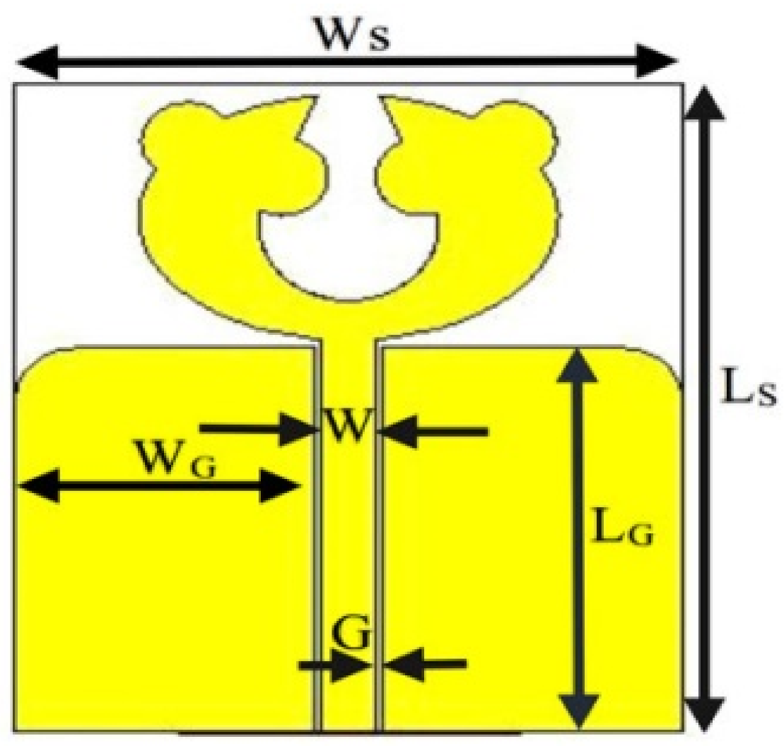 | Advantage: Usage of metamaterial and array configuration gives increased gain and efficiency Disadvantage: Large size | Mu-negative metamaterial | 7.2–9.2 | |
| [17] | Wearable Microwave Medical Imaging | 2.9 | - | - | Advantage: Easy to fabricate as it is made of flexible polyester Disadvantage: Complex design and possibility of coupling between the slots | Monopole antenna with triangular and parallel slots on the lower portion of the radiating patch | 1.1–4.0 | |
| [19] | Wireless body area network (WBAN) | 1.75–5.6 | 90.6 | 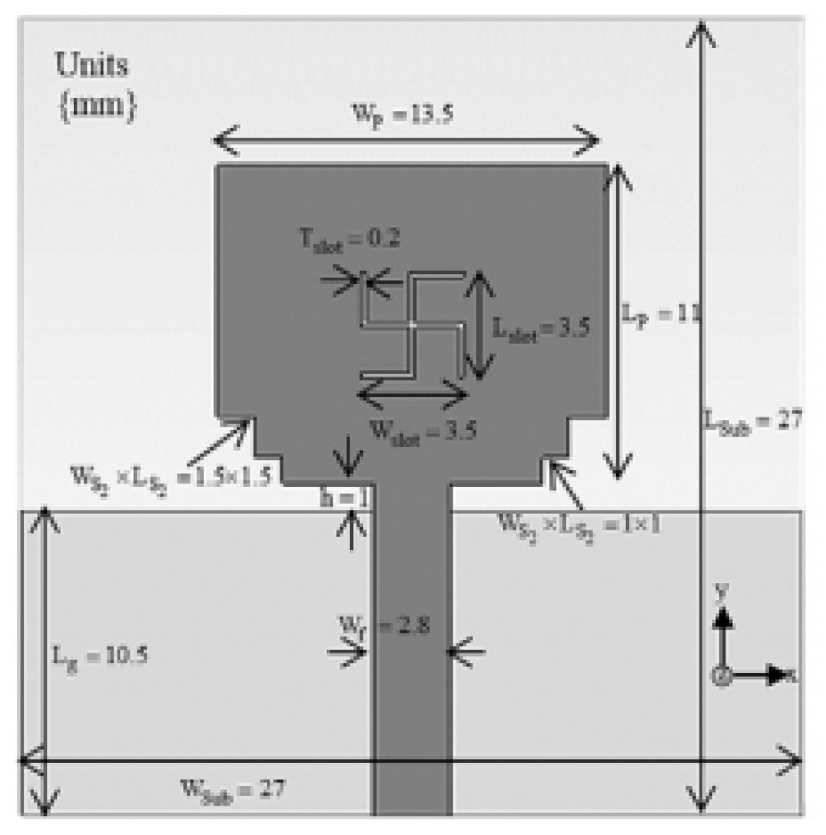 | Advantage: Good gain and efficiency Disadvantage: The radiation pattern is not stable. | Partial ground plane with a slot in the patch and notches at the bottom | 3.1–10.6 | |
| [20] | 5G wireless communication | 3.3 | 69 | - | Advantage: Flexible antenna with good efficiency Disadvantage: Gain can be improved. | Cutting two slots in the ground plane | 2.2–25 | |
| [21] | Wireless body area network (WBAN) | 6 | - | 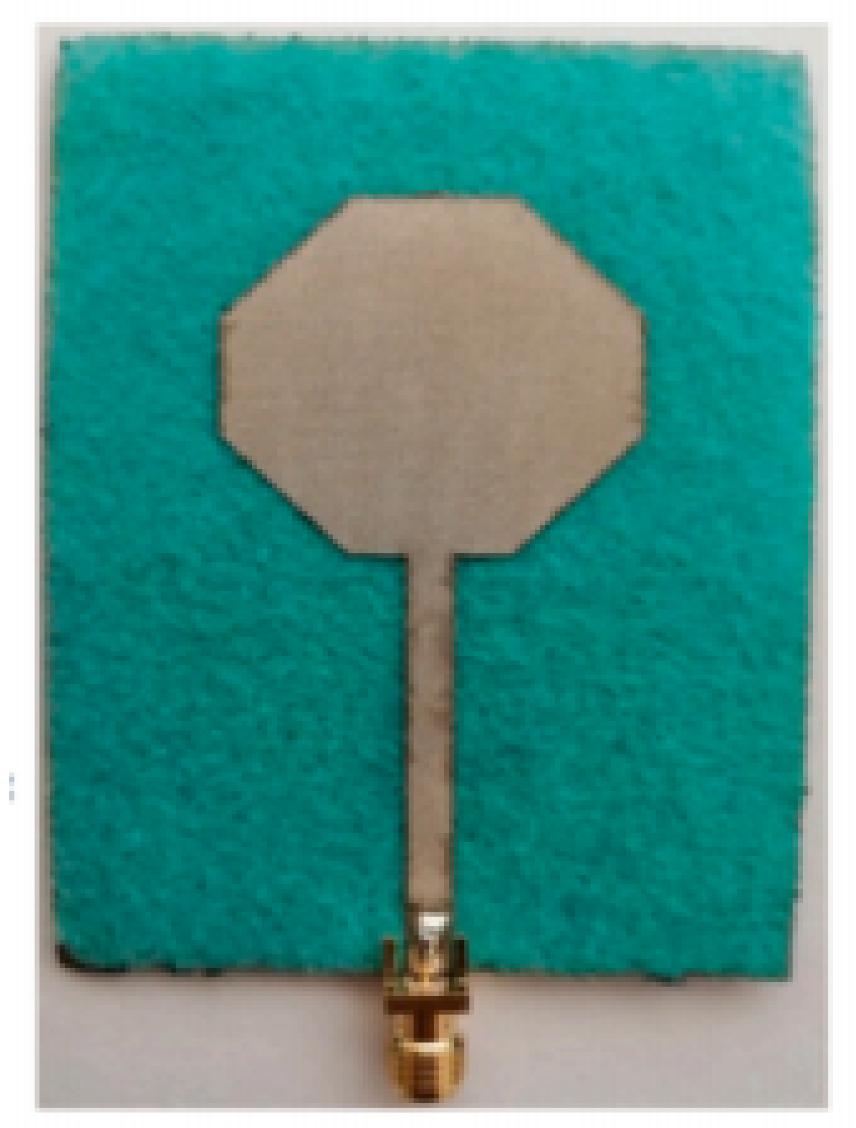 | Advantage: Less thickness Low SAR Disadvantage: Large size | Use of rectangular ground plane and a circular parasitic patch at the back of the substrate | 4.5–13 | |
| [24] | Wireless USB Dongle | 3.2–4.6 | 94 | - | Advantage: Good radiation characteristics Disadvantage: Ground plane length hampers impedance bandwidth | Two wide ended radiated arms and beveled feed | 2.9–10.61 | |
| [30] | Mobile phone | - | 88 | - | Advantage: Good impedance matching and efficiency Disadvantage: Design complexity | Utilization of tapered structure | 0.8–6 | |
| [40] | Human respiration and heart rate detection | 14 | - | 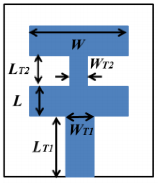 | Advantage: High Gain antenna Disadvantage: The radiation pattern can be improved. | Doppler radar technique | 10 | |
| [41] | Microwave Radiology Imaging (MRI) applications | 6 | - |  | Advantage: Good performance for MRI applications Disadvantage: Large size | Slotted Triangular Flared (STF) patch | 7.8–15 | |
| [43] | Detection of Void Inside Concrete Specimens | 9.5 | - | - | Advantage: It gives high-quality image of lost materials. Disadvantage: Large size | Use of tapered ground plane | 1–30 | |
| [45] | Near-Field synthetic aperture radar (SAR) Imaging | 3 | - | - | Advantage: High impedance bandwidth and planar structure Disadvantage: Less gain | circularly polarized crossed dipole antenna with elliptical arms vacated by rotated elliptical slot. | 1.6–7.2 |
| Ref. No. | Size (mm2) | Antenna Design | Gain (dBi) | Efficiency | Methodology | Notching Structure | Advantage/Disadvantage | Notch Frequency Range (GHz) |
|---|---|---|---|---|---|---|---|---|
| [82] | - | 7 | - | The rectangular aperture is designed by minimizing the aperture area and causing impedance matching. | Rectangular slot with T stub feed | Advantage: Good radiation pattern. Disadvantage: Gain decrease in second resonant mode due to cross-polarization decoupling | 5–6 | |
| [83] | - | 3.5 | - | A parasitic strip to the lower end of the antenna with varied lengths causes notching. | Elliptic slot with three steps | Advantage: Good radiation characteristics and impedance matching. Disadvantage: Poor cross polarization | 5.1–5.8 | |
| [85] | - | 7 | - | The concentration of current on the conductor’s outer edge and the fork-shaped strip causes band rejection in selected bands | T shaped slot in a fork-shaped strip | Advantage: Stable radiation pattern. Disadvantage: There is distortion in the incoming signal in the frequency band of interest. | 5.1–5.8 | |
| [86] | - | 4 | - | Square ring resonator is used to achieve notching. | Octagonal slot with a rectangular stub for tuning | Advantage: Sharp frequency notch. Disadvantage: Radiation pattern can be improved. | 5.2–5.9 | |
| [87] |  | 5 | - | A semi-elliptical patch with dielectric material on both sides of the patch increases the effective patch, thereby increasing the bandwidth. | Two arc-shaped slots which are connected | Advantage: Good radiation pattern and good gain. Disadvantage: Complex design | 5.1–5.9 | |
| [88] | - | 5.4 | - | A hexagonal patch with two slits is used for enhanced bandwidth and band rejection. | Hexagonal patch with two slits for band rejection | Advantage: Stable radiation pattern and good gain Disadvantage: Notch is not sharp. | 5.1–5.8 | |
| [89] |  | 5 | - | UWB antenna with U-shape slot and asymmetric rectangular slit | U-shape slot | Advantage: Stable gain and radiation characteristics Disadvantage: Complex structure | 4.5–4.6, 7.0–7.4, 8.7–9.3 | |
| [90] |  | 6 | - | Application of fractal geometry in the hexagonal monopole | Y-shape slot | Advantage: Stable radiation pattern and good time-domain characteristics Disadvantage: Complex structure | 5.1–5.8 | |
| [91] |  | 4 | - | Use of Koch Snowflake iterative design | Snowflake slot | Advantage: Stable radiation pattern Disadvantage: Complex design | 5.1–5.8 | |
| [92] |  | 3.5 | 80 | Use of fractal Koch with CPW feeding | Fractal Koch shape slot | Advantage: Circular polarization Disadvantage: Low gain at 1.5 GHz | 1.5–5.4 | |
| [93] |  | 6.5 | 68 | Fractal Koch with the stub of T-shape | Fractal slot | Advantage: Stable radiation pattern Disadvantage: Low efficiency | 1.7–1.8, 2.2–3.1 | |
| [94] |  | 5.98 | - | Use of two similar ellipses on a hexagon-shaped radiating patch | two C-shape slots | Advantage: Compact size Disadvantage: Radiation pattern is moderate. | 3.1–3.8, 4.8–6.1, 7.2–7.8 | |
| [95] |  | 3.2 | - | Use of decoupling structure, multi-slit, and multi-slot concepts | Multi-slot | Advantage: Low mutual coupling ( ) Low ECC Disadvantage: Gain can be improved. | 3.2–3.7, 5.0–5.9, 7.0–7.9 | |
| [96] |  | 2.91 | 70–90 | UWB antenna with T-shaped stub and open-ended slot | Open-ended slot | Advantage: Stable radiation pattern and low ECC Disadvantage: Low gain | 4.3–5.9, 6.5–7.4 | |
| [103] | - | 3.6 | 75 | The offset microstrip-fed slot antenna | Rhombic slot | Advantage: Sharp notch, low mutual coupling, and low envelope correlation coefficient Disadvantage: Low efficiency | 5.0–5.9 | |
| [104] | - | 3 | 75 | Use of orthogonal pairs of differential-fed elements and the irregular octagonal ground plane | Octagonal- shaped slot | Advantage: Wide bandwidth and low cross-polarization Disadvantage: Measured efficiency is lower than simulated efficiency | 5–6.1 | |
| [105] |  | 2.5 | - | Use of two bevels in the upper edge of the rectangular ground plane | Round shaped slot, C-shaped slots | Advantage: Stable gain and sharp notch band Disadvantage: Unstable radiation pattern | 3.3–3.7, 5.1–5.8, and 7.1–7.7 | |
| [106] |  | 5 | - | Monopole patch antenna consists of semicircular radiator truncated with a trapezoidal structure and a ground of rectangular shape | Inverted-L slots | Advantage: Simple structure and easy to fabricate Disadvantage: Unstable radiation pattern | 3.3–3.8, 5.1–5.9, and 8.0–8.7 | |
| [107] |  | 4.9 | 90 | CPW fed printed monopole antenna | Three rectangular slots | Advantage: Simple structure and compact size Disadvantage: Gain is not flat throughout the operating band. | 5.1–5.8 and 7.2–8.3 | |
| [108] |  | 5.1 | 97 | CPW fed UWB antenna with EBG structure | Rectangular slot on the ground plane | Advantage: Good gain and better efficiency Disadvantage: Large size | 5.1–5.8, 7.1–7.7 | |
| [109] |  | 6.5 | - | Antipodal Vivaldi antenna with resonant parallel strip | Resonant parallel strip | Advantage: Stable radiation pattern Disadvantage: Large size | 3.3–3.6 | |
| [110] |  | 4.8 | 55 | A quasi-U-shape antenna with four stubs and a stepped ground plane | stepped slot | Advantage: Stable radiation pattern Disadvantage: Less efficiency | 4.9–5.4, 5.6–5.9 | |
| [111] |  | 6 | - | Rectangular patch antenna with H-slot on patch along with a feed with a U-slot | H-shaped and U-shaped slot | Advantage: Good gain Disadvantage: Moderate radiation pattern | 5.1–5.8, 7.2–7.7, 7.9–8.4 | |
| [112] |  | 6 | - | Y-shaped antenna with slot of inverted U-shape along with slot of C-shape on radiating patch and ground plane | inverted U-shaped and a C-shaped slot | Advantage: Omnidirectional radiation pattern Disadvantage: phase response is little distorted. | 3.4–4.0, 5.1–5.9, 6.7–8.0, 8.3–9.1, 9.3–10.6 | |
| [113] | 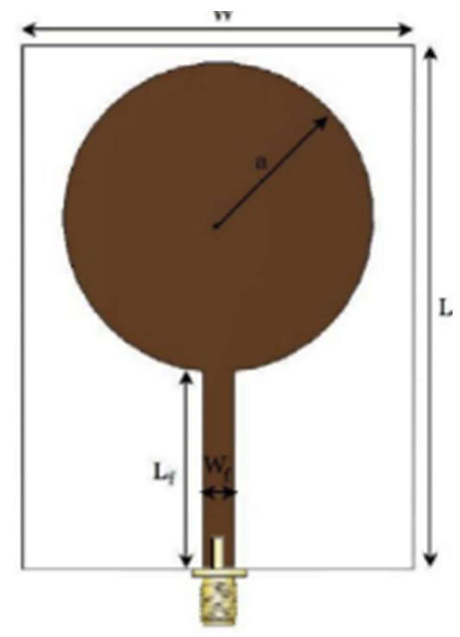 | 4.4 | 95 | Circular monopole antenna with DGS and resonators of inverted-U and the iron shape on the substrate | Rectangular slot | Advantage: Compact size Disadvantage: Distortion in the radiation pattern | 5–5.4, 7.8–8.4 | |
| [114] |  | 5 | - | CPW-fed UWB antenna with sharp bandstop filter (BSF) | Bandstop filter (BSF) | Advantage: Omnidirectional radiation pattern Disadvantage: Distortions at higher frequency in E plane | 5.7–5.8, 8.0–8.4 | |
| [115] | 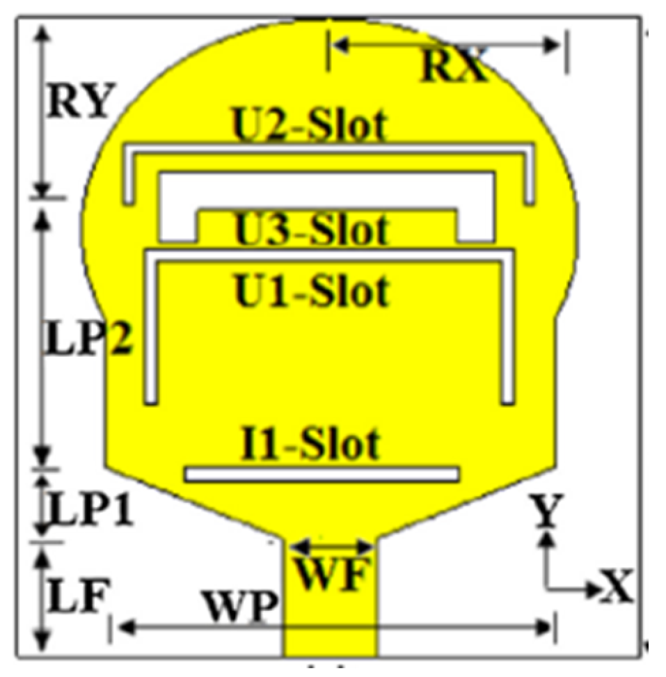 | 6.15 | - | Monopole ellipzoidal antenna with three slots of inverted U-shape and one slot of I-shape slots | Inverted U-shape slot, I-shape, and rectangular slot | Advantage: Omnidirectional radiation pattern and linear phase Disadvantage: Complex design | 3.2–3.9, 4.3–5.0, 5.5–6.6, 7.9–9.3 | |
| [116] |  | 5.8 | - | Antenna with two Mushroom and One Uniplanar EBG Structures | Electromagnetic Band Gap (EBG) structure | Advantage: Good diversity parameters obtained Disadvantage: Less isolation | 3.3–3.6, 5–6, 7.1 –7.9 | |
| [117] |  | - | - | CPW-fed Hexagonal Fractal Antenna with design of the grooves in the ground plane and use of fractal geometry and Notch filters. | Hexagonal and U-shape slot | Advantage: Omnidirectional radiation pattern and good return loss Disadvantage: Complex structure | 5.1–5.9 | |
| [118] |  | 2.2 | 96 | A QSCF antenna with loading slot and stub | U-shaped slot | Advantage: omnidirectional radiation pattern Disadvantage: Low gain | 3.3–3.8, 5.1–5.8, 7.2–8.3 | |
| [119] |  | 6 | - | inverted-A Monopole UWB antenna with defected ground structure (DGS). | Rectangular slot | Advantage: High isolation and low diversity performance Disadvantage: More number of multipath | 3.9–4.2, 5.1–5.8 | |
| [120] |  | 5 | 80 | A double fork-shaped CPW fed structure and a simple symmetrical inverted L-shaped stub resonator | Inverted L-shaped stub resonator. | Advantage: Small size Omnidirectional radiation pattern Disadvantage: At 20 GHz radiation pattern is less bidirectional in the E-plane | 3.4–3.8, 4.5–5.5 | |
| [121] |  | 4 | - | UWB monopole antenna with the defective ground structure of P-shape resonators, slot resonator pair, a stub of T-shape, and conductor plane of two slits. | Resonator, slot, and slit | Advantage: Sharp notched band and good time-domain characteristics Disadvantage: Complex design | 3.3–3.6, 5.1–5.3, 5.6–5.9, 7.2–7.6, 7.8–8.2, 9.2–9.7 | |
| [128] | 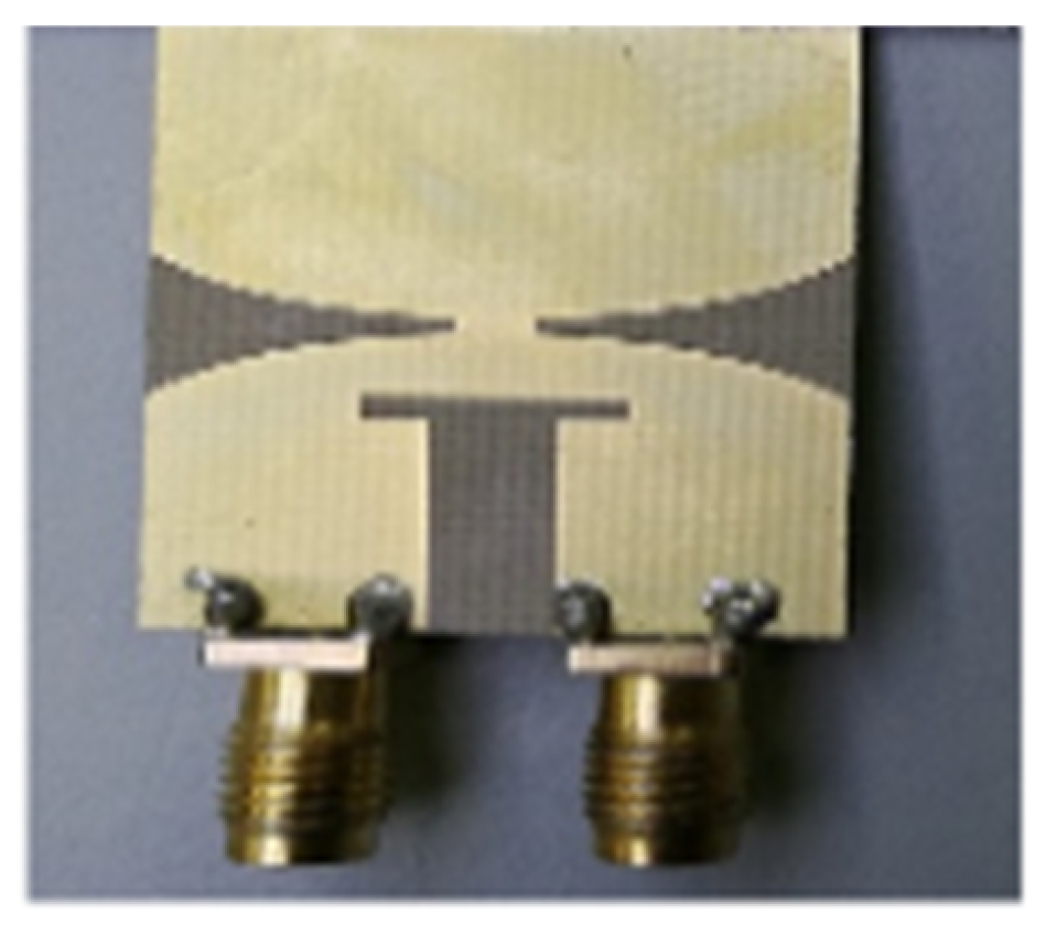 | 5 | - | UWB Vivaldi antenna with two microstrip feeding lines, T-shaped slot on the ground plane, and two split-ring resonators (SRR) | T-shaped slot | Advantage: Very low ECC and stable gain Disadvantage: Isolation can be improved | 5.3–5.8, 7.8–8.5 | |
| [129] |  | 6.2 | 70 | Antenna with a rectangular patch and a partial ground plane | open-loop resonator | Advantage: Compact size and good gain Disadvantage: Less efficiency | 3.3–3.8, 3.7– 4.2, 5.1–5.8, 5.5–5.9 | |
| [130] |  | 4 | - | Antenna with elliptic radiator and a rectangle ground plane using ESRR and RSRR with U-shaped parasitic strip | elliptic split ring resonator (ESRR) and a round split ring resonator (RSRR) | Advantage: Compact size, wider bandwidth, and more notched bands Disadvantage: Distortion in radiation pattern | 2.9–3.3, 3.7–3.8, 4.4–4.5, 5.3–5.5, 7.0–7.3, 7.5–8.0 | |
| [131] |  | 5.2 | - | Metamaterial based ring resonators | Double-slotted ring resonators (SRR), circular (C-SRR), and square (S-SRR) | Advantage: Multiple band frequencies rejection and stable radiation patterns Disadvantage: Complex structure | 4.6–5.4 | |
| [132] |  | - | - | Metamaterial based split ring resonator | SRR on the ground plane | Advantage: Compact size and simple structure Disadvantage: Disturbance in the radiation pattern | 5–6 | |
| [133] |  | 9.94 | 58 | Metamaterial based split ring resonator | A complementary split-ring resonator (CSRR) and the split ring resonator (SRR) | Advantage: Good isolation, low ECC, and stable gain Disadvantage: Low efficiency | 3.4–3.9, 5.7–6.2 | |
| [134] |  | 4.71 | - | Metamaterial based split ring resonator | Annular SRR slot and a rectangular SRR | Advantage: Better isolation and good gain Disadvantage: Large size | 3.3–3.9, 4.7–5.5 | |
| [135] |  | 3.86 | - | EBG and Metamaterial based split ring resonator | 2 split-ring resonators (SRR) | Advantage: Compact size and stable gain Disadvantage: Poor isolation | 3.4–3.9, 5.1–5.8, 7.2–7.7 | |
| [136] |  | 3.47 | - | Annular defected ground | Multi resonant metamaterial cell | Advantage: Compact size and simple structure | – | |
| [137] |  | 8 | 79.4 | Parasitic decoupler | U-shape slot on the patch | Advantage: Higher gain, Good isolation Disadvantage: Less efficiency | 4.2–5.8 | |
| [138] |  | 4 | - | Metamaterial based split ring resonator | Split ring resonator (SRR) and U-shape slot | Advantage: Simple structure and wide band Disadvantage: High dispersion | 3.3–3.8, 5.1–5.8, 7.2–8.3 | |
| [139] |  | 4 | - | Metamaterial based complementary split-ring resonator | Slotted complementary SRRs structures | Advantage: Compact size, simple structure, and wide band Disadvantage: Gain is not constant in the operating band. | 4.8–5.7 |
| Ref. No. | Antenna Design | Gain (dBi) | Efficiency (%) | Advantage/Disadvantage | Frequency Reconfiguration Mechanism | Design Methodology | Operating Frequency (GHz) | |
|---|---|---|---|---|---|---|---|---|
| [144] | 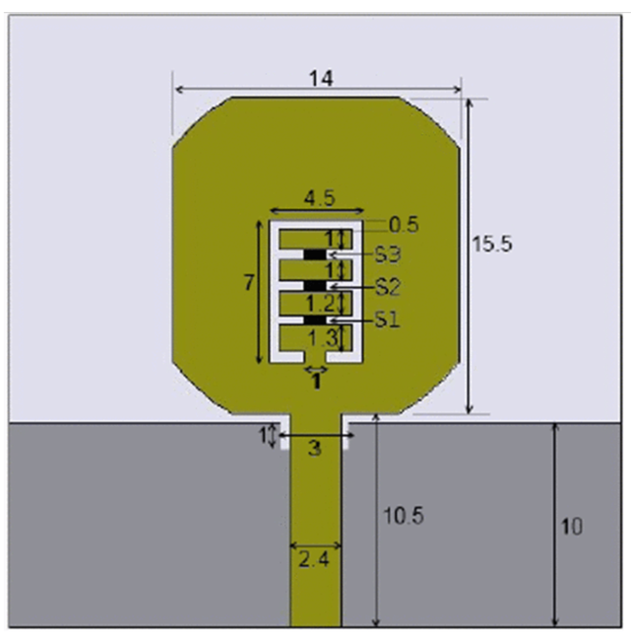 | 3.12 | - | Advantage: Wider band notch Disadvantage: Less gain | Electronic switches | Complementary split-ring resonators (CSRRs) | 3.8–9.5 | |
| [145] | 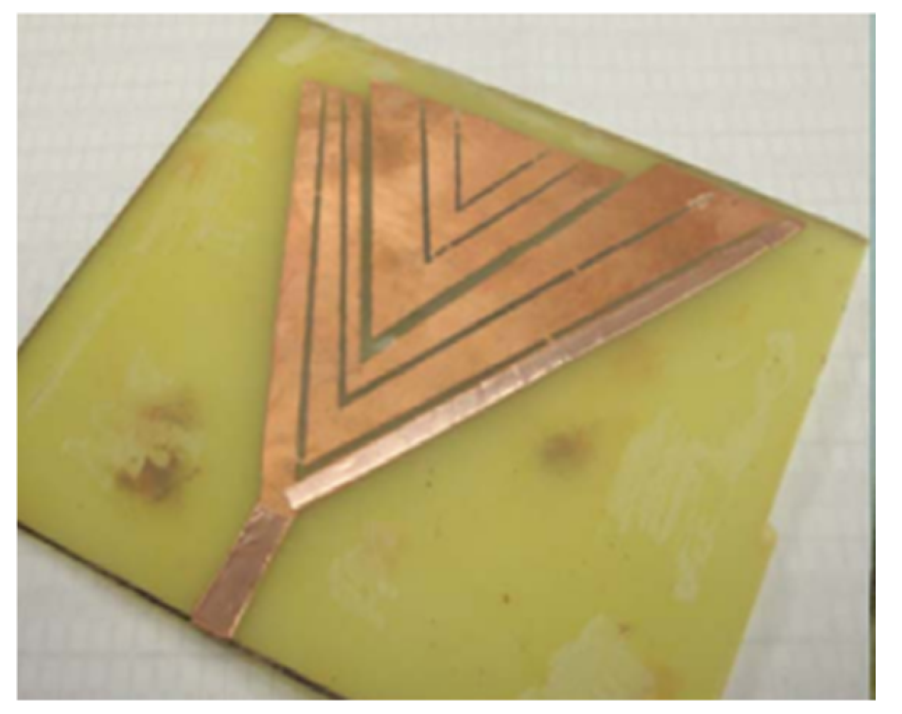 | 16 | 70 | Advantage: Compact size and good gain Disadvantage: Less efficiency | PIN diode | Monopole of V- shape and electromagnetic band-gap structure with U-shaped slot | 0.6–30 | |
| [146] |  | - | - | Advantage: Each notch band can be controlled separately. Simple design Disadvantage: Complex biasing circuit | PIN diodes | A CPW fed UWB antenna using a defected ground-plane slit | 2.8–10.6 | |
| [147] |  | 5 | - | Advantage: More unlicensed users can operate since it dynamically rejects a band. Disadvantage: The efficiency of the proposed antenna needs to be further explored. | RF switches | Filter antennas using CSRRs and SRRs | 2.1–7.5 | |
| [148] |  | 4.5 | - | Advantage: Simple structure and constant group delay Disadvantage: Distortion during pulse transmission | RF switches | Shorting the U-shaped slots on the patch | 2.4–10.8 | |
| [149] |  | 4 | - | Advantage: Shows reconfiguration characteristics for microwave and WiMax applications Disadvantage: The antenna gain variations are not uniform. | Rotation DR with stepper motor | Rectangular split-ring slot | 3.2–5.1 | |
| [150] |  | - | - | Advantage: It can mitigate UWB interference and the notch has narrowband functionality. Disadvantage: The biasing circuit utilized to obtain reconfiguration affects the gain and radiation pattern of the antenna drastically. | PIN and varactor diodes | Switchable slots | 3.1–10.6 | |
| [151] | - | 5 | 90 | Advantage: Simple biasing structure gives suitable frequency reconfiguration and tenability Disadvantage: Tuning leads to stray capacitance. | PIN diodes and the varactor diode | CPW loaded with a switchable/tunable S-SRR along with | 2.1–10.6 | |
| [152] | - | 7 | 80 | Advantage: Compact size, good gain, and radiation efficiency Disadvantage: Complex design | PIN diode | Slot Antenna with stepped slots | 2.8–10.7 | |
| [153] |  | 5 | - | Advantage: It gives seven modes of operation Disadvantage: There is distortion in the radiation pattern at a higher frequency. | PIN diode | Three slots in the ground plane with parasitic strips on feed line and PIN diodes for switching | 3.1–10.6 | |
| [154] | 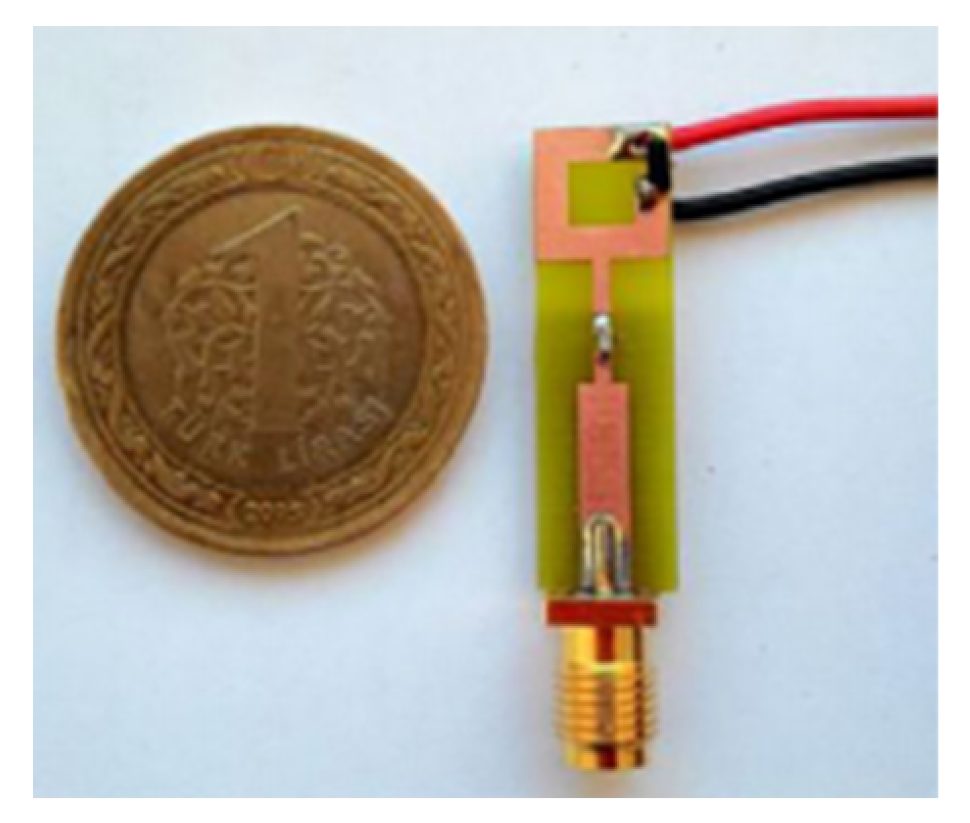 | 4 | >70 | Advantage: Compact size, stable gain and reconfigurability Disadvantage: The proposed antenna does not show stable radiations at higher operating frequencies. | PIN diode | G-shaped monopole with PIN diode | 2.8–12.6 | |
| [155] |  | 3 | 80–95 | Advantage: Good radiation efficiency Disadvantage: The biasing circuit greatly affects the return loss, gain, and radiation pattern. | PIN diode | Monopole antenna with T-shaped slot | 3–14 | |
| [156] | 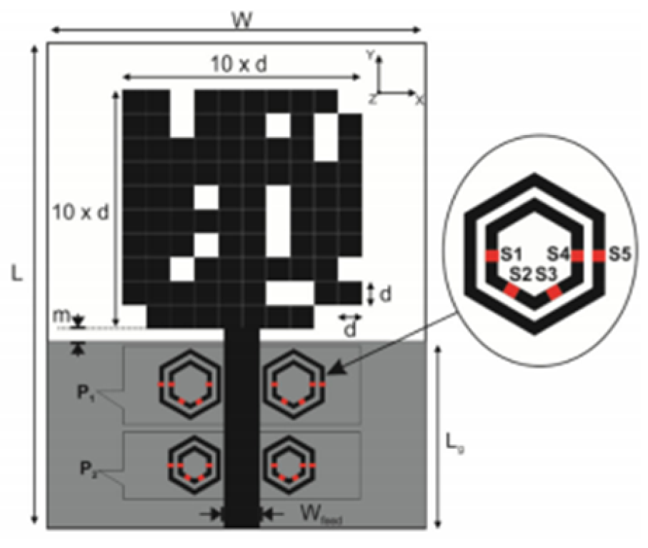 | 6 | - | Advantage: Filters the frequency sweep of narrowband from 5.7 GHz to 8 GHz Disadvantage: Complex structure | PIN diodes | Hexagonal SRR metamaterial cells | 2.8–11 | |
| [157] |  | 4 | 80–90 | Advantage: Eliminates the interference of LTE WiMaz frequency range Disadvantage: Design technique affects radiation characteristics | Varactor diodes | Split-ring slot | 1.9–10.5 | |
| [158] | 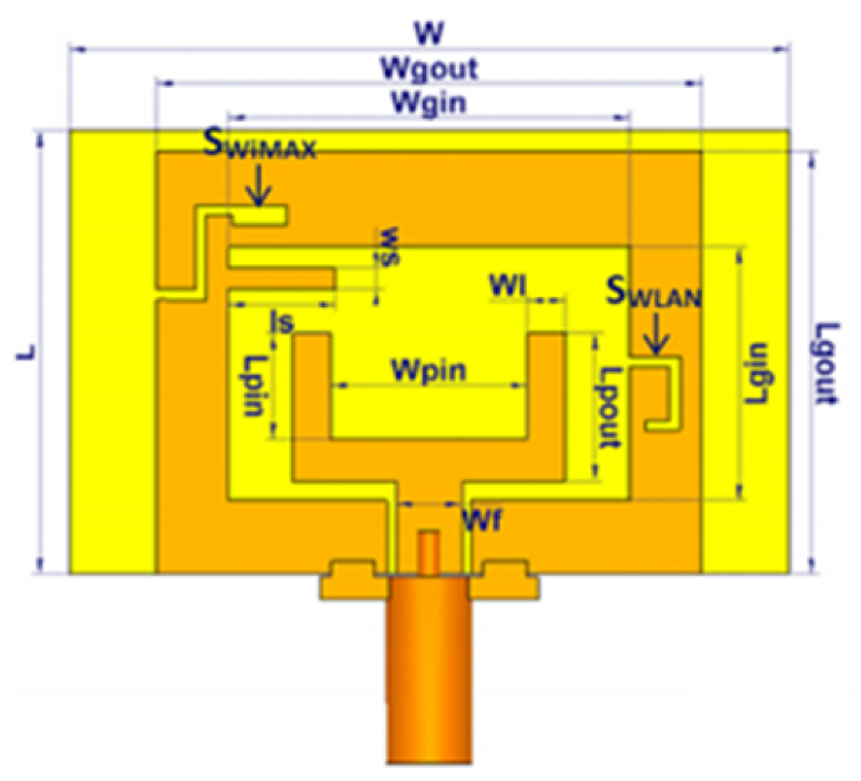 | 6 | 70 | Advantage: Successfully filters the WiMax and WLAN signals from the operating band Disadvantage: Efficiency can be improved. | Use of two PIN diodes | Two open-ended slot | 3–10.6 |
Publisher’s Note: MDPI stays neutral with regard to jurisdictional claims in published maps and institutional affiliations. |
© 2021 by the authors. Licensee MDPI, Basel, Switzerland. This article is an open access article distributed under the terms and conditions of the Creative Commons Attribution (CC BY) license (https://creativecommons.org/licenses/by/4.0/).
Share and Cite
Kumar, O.P.; Kumar, P.; Ali, T.; Kumar, P.; Vincent, S. Ultrawideband Antennas: Growth and Evolution. Micromachines 2022, 13, 60. https://doi.org/10.3390/mi13010060
Kumar OP, Kumar P, Ali T, Kumar P, Vincent S. Ultrawideband Antennas: Growth and Evolution. Micromachines. 2022; 13(1):60. https://doi.org/10.3390/mi13010060
Chicago/Turabian StyleKumar, Om Prakash, Pramod Kumar, Tanweer Ali, Pradeep Kumar, and Shweta Vincent. 2022. "Ultrawideband Antennas: Growth and Evolution" Micromachines 13, no. 1: 60. https://doi.org/10.3390/mi13010060