
Dynamic Modeling and Attitude Decoupling Control for a 3-DOF Flexible Piezoelectric Nano-Positioning Stage Based on ADRC

Abstract
:1. Introduction
2. Problem Statement
3. Dynamic Modeling
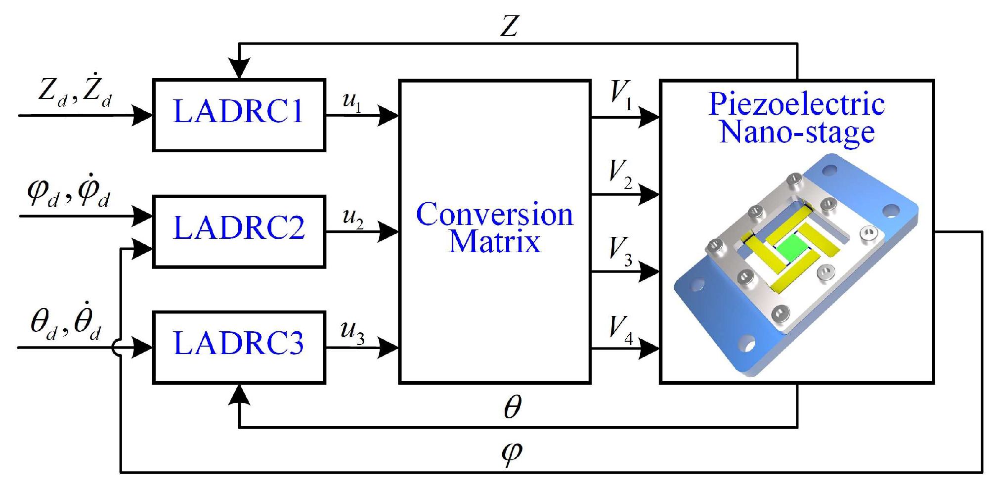
4. Attitude Decoupling Control of the Piezoelectric Nano-Positioning Stage
4.1. Conversion Matrix of Control Variables
4.2. Linear Active Disturbance Rejection Control
4.2.1. Linear Extended State Observer Design
4.2.2. Feedback Controller Design
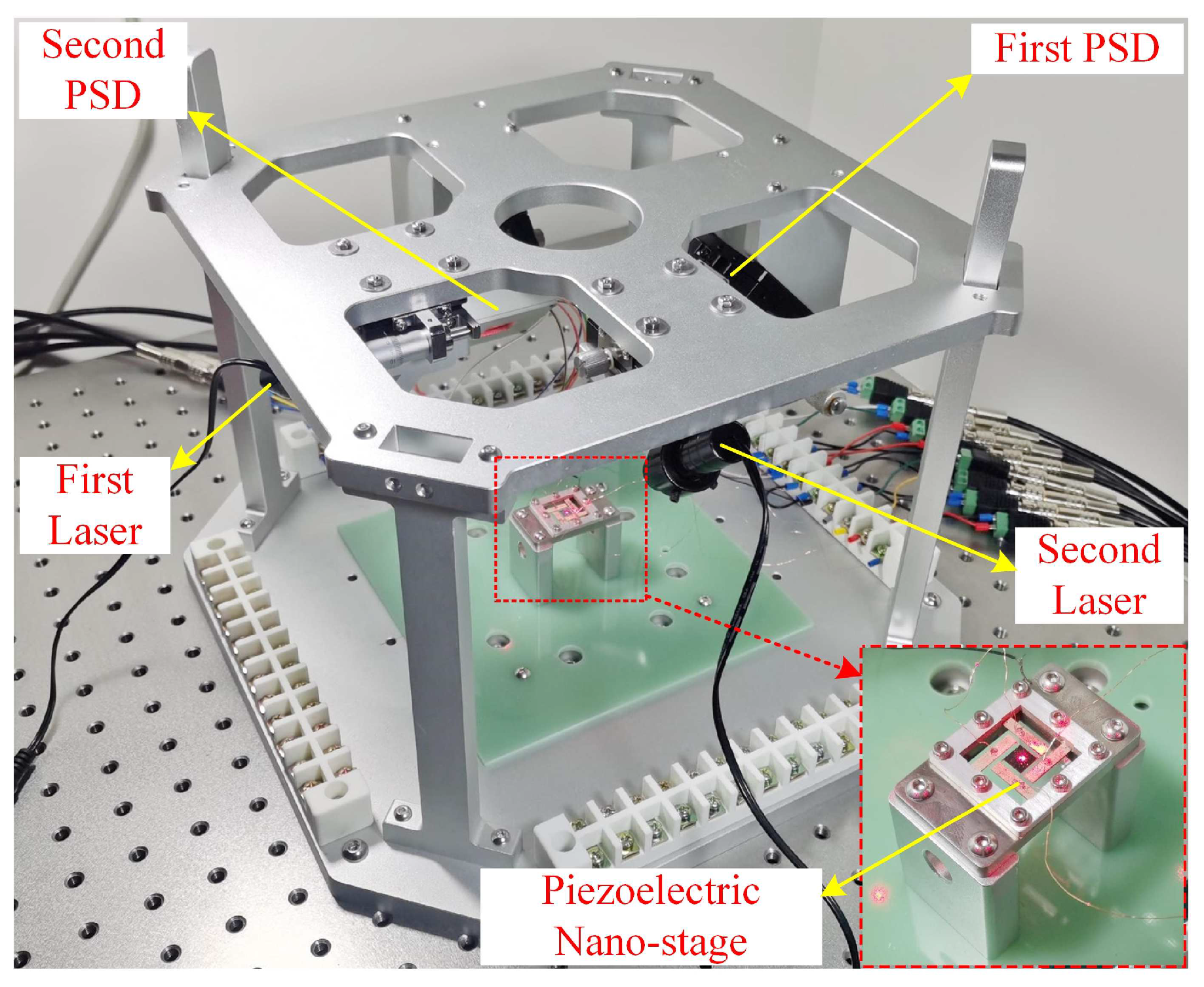
5. Detection Method and Results
5.1. Detection Method and Experimental Setup
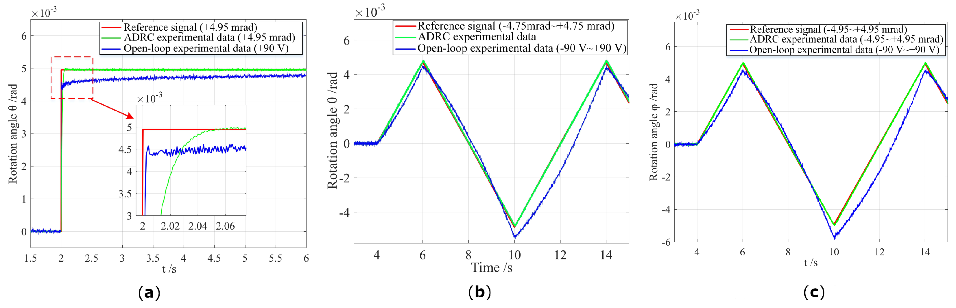
5.2. Experimental Results
6. Conclusions
Author Contributions
Funding
Conflicts of Interest
Abbreviations
| DOF | Degree of Freedom |
| ADRC | Active Disturbance Rejection Control |
| PSD | Position-Sensitive Detector |
| ESO | Extended State Observer |
Nomenclature
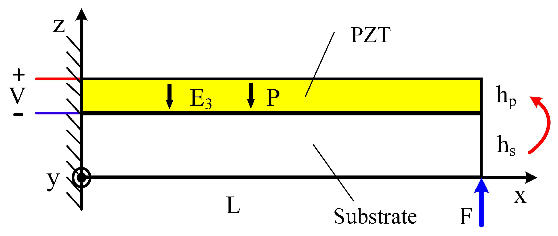
| strain slope of unimorph benders | |
| b | width of bender |
| d | center distance between detector (PSD) and mirror |
| coefficient of piezoelectric strains | |
| electric field of unimorph benders | |
| F | force (general) |
| thickness of each layer of piezoelectric benders (defined by index) | |
| L | length of bender |
| P | polarization direction |
| compliance coefficient of piezo and substrate material | |
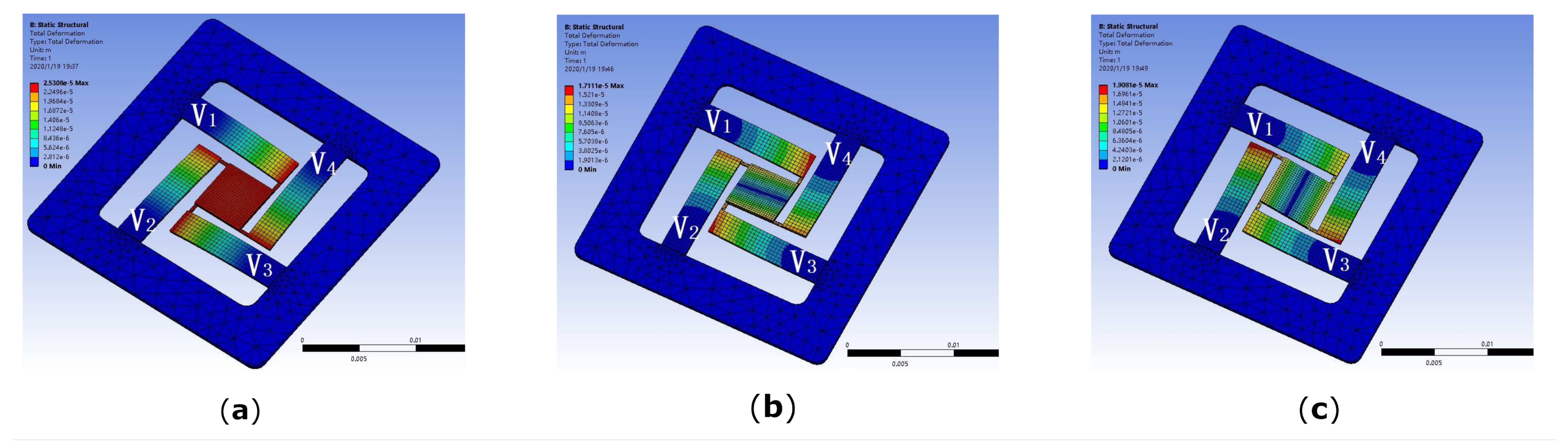
| voltage applied to unimorph benders (defined by index) | |
| space coordinates |
Appendix A. Electro-Mechanical Conversion Coefficient
Appendix B. Equivalent Stiffness
References
- Liang, C.; Wang, F.; Shi, B.; Huo, Z.; Zhou, K.; Tian, Y.; Zhang, D. Design and control of a novel asymmetrical piezoelectric actuated microgripper for micromanipulation. Sens. Actuators A 2018, 269, 227–237. [Google Scholar] [CrossRef]
- Ye, L.; Zhang, G.; You, Z. 5 V compatible two-axis PZT driven MEMS scanning mirror with mechanical leverage structure for miniature LiDAR application. Sensors 2017, 17, 521. [Google Scholar] [CrossRef] [PubMed]
- Kim, K.; Choi, Y.M.; Gweon, D.G.; Lee, M.G. A novel laser micro/nano-machining system for FPD process. J. Mater. Process. Technol. 2008, 201, 497–501. [Google Scholar] [CrossRef]
- Bai, Y.; Yeow, J.T.W.; Constantinou, P.; Damaskinos, S.; Wilson, B.C. A 2-D micromachined SOI MEMS mirror with sidewall electrodes for biomedical imaging. IEEE/ASME Trans. Mechatron. 2010, 15, 501–510. [Google Scholar]
- Chae, K.W.; Kim, W.B.; Jeong, Y.H. A transparent polymeric flexure-hinge nanopositioner, actuated by a piezoelectric stack actuator. Nanotechnology 2011, 22, 335501. [Google Scholar] [CrossRef]
- Zhu, Y.; Liu, W.; Jia, K.; Xie, H. A piezoelectric unimorph actuator based tip-tilt-piston micromirror with high fill factor and small tilt and lateral shift. Sens. Actuators A 2011, 167, 495–501. [Google Scholar] [CrossRef]
- Yang, Y.L.; Wei, Y.D.; Lou, J.Q.; Fu, L.; Fang, S. Design and control of a multi-DOF micromanipulator dedicated to multiscale micromanipulation. Smart Mater. Struct. 2017, 26, 115016. [Google Scholar] [CrossRef]
- Roy, N.K.; Cullinan, M.A. Fast frajectory fracking of a flexure-Based, multiaxis nanopositioner with 50-mm travel. IEEE/ASME Trans. Mechatron. 2018, 23, 6. [Google Scholar] [CrossRef]
- Zhang, X.; Xu, Q. Design and development of a new 3-DOF active-type constant-force compliant parallel stage. Mech. Mach. Theory 2019, 140, 654–665. [Google Scholar] [CrossRef]
- Zhang, X.; Xu, Q. Design and testing of a novel 2-DOF compound constant-force parallel gripper. Precis. Eng. 2019, 56, 53–61. [Google Scholar] [CrossRef]
- Hao, G.; He, X.; Awtar, S. Design and analytical model of a compact flexure mechanism for translational motion. Mech. Mach. Theory 2019, 142, 103593. [Google Scholar] [CrossRef]
- Wang, F.; Shi, B.; Tian, Y.; Huo, Z.; Zhao, X.; Zhang, D. Design of a novel dual-axis micromanipulator with an asymmetric compliant structure. IEEE/ASME Trans. Mechatron. 2019, 24, 2. [Google Scholar] [CrossRef]
- Ling, M.; Cao, J.; Pehrson, N. Kinetostatic and dynamic analyses of planar compliant mechanisms via a two-port dynamic stiffness model. Precis. Eng. 2019, 57, 149–161. [Google Scholar] [CrossRef]
- Matsushita, S.; Kanno, I.; Adachi, K.; Yokokawa, R.; Kotera, H. Metal-based piezoelectric microelectromechanical systems scanner composed of Pb(Zr,Ti)O3 thin film on titanium substrate. Microsyst. Technol. 2012, 18, 765–771. [Google Scholar] [CrossRef]
- Chen, C.D.; Wang, Y.J.; Chang, P. A novel two-axis MEMS scanning mirror with a PZT actuator for laser scanning projection. Opt. Express 2012, 20, 27003–27017. [Google Scholar] [CrossRef]
- Pan, C.; Liao, W. A new two-axis optical scanner actuated by piezoelectric bimorphs. Int. J. Optomechatronics 2012, 6, 336–349. [Google Scholar] [CrossRef]
- Fleming, A.J.; Yong, Y.K. An ultra-thin monolithic XY nanopositioning stage constructed from a single sheet of piezoelectric material. IEEE/ASME Trans. Mechatron. 2017, 22, 2611–2618. [Google Scholar] [CrossRef]
- Omidbeike, M.; Yong, Y.K.; Moore, S.I.; Fleming, A.J. A five-axis monolithic nanopositioning stage constructed from a bimorph piezoelectric sheet. In Proceedings of the IEEE 2019 International Conference on Manipulation, Automation and Robotics at Small Scales (MARSS), Helsinki, Finland, 1–5 July 2019; pp. 1–6. [Google Scholar]
- Chen, H.; Li, M.; Zhang, Y.; Xie, H.; Chen, C.; Peng, Z.; Su, S. H∞ robust control of a large-piston MEMS micromirror for compact fourier transform spectrometer systems. Sensors 2018, 18, 508. [Google Scholar] [CrossRef]
- Chen, H.; Sun, Z.; Sun, W.; Yeow, J.T.W. Twisting sliding mode control of an electrostatic MEMS micromirror for a laser scanning system. IEEE/CAA J. Autom. Sinica 2019, 6, 1060–1067. [Google Scholar] [CrossRef]
- Aphale, S.S.; Devasia, S.; Reza Moheimani, S.O. High-bandwidth control of a piezoelectric nanopositioning stage in the presence of plant uncertainties. Nanotechnology 2008, 19, 125503. [Google Scholar] [CrossRef]
- Chen, N.; Yan, P. Dynamic modeling and validation of a novel 3-DOF flexible thin sheet nano-manipulator with piezoelectric material bonded. Smart Mater. Struct. 2020, 29, 045035. [Google Scholar] [CrossRef]
- Xiao, R.; Xu, M.; Shao, S.; Tian, Z. Design and wide-bandwidth control of large aperture fast steering mirror with integrated-sensing unit. Mech. Syst. Signal Process. 2019, 126, 211–226. [Google Scholar] [CrossRef]
- Yang, C.; Wang, Y.; Youcef-Toumi, K. Hierarchical anti-disturbance control of a piezoelectric stage via combined disturbance observer and error-based ADRC. IEEE Trans. Ind. Electron. 2021, 69, 5060–5070. [Google Scholar] [CrossRef]
- Tang, H.; Li, J.; Jia, Y.; Gao, J.; Li, Y. Development and testing of a large-stroke nanopositioning stage with linear active disturbance rejection controller. IEEE Trans. Autom. Sci. Eng. 2022, 19, 2461–2470. [Google Scholar] [CrossRef]
- Fareh, R.; Khadraoui, S.; Abdallah, M.Y.; Baziyad, M.; Bettayeb, M. Active disturbance rejection control for robotic systems: A review. Mechatronics 2021, 80, 102671. [Google Scholar] [CrossRef]
- Wu, Z.; Shi, G.; Li, D.; Liu, Y.; Chen, Y. Active disturbance rejection control design for high-order integral systems. ISA Trans. 2022, 125, 560–570. [Google Scholar] [CrossRef]
- Chen, N.; Yan, P.; Ouyang, J. A generalized approach on bending and stress analysis of beams with piezoelectric material bonded. Sens. Actuators A 2019, 290, 54–61. [Google Scholar] [CrossRef]
- Fang, L.; Zhang, L. Modeling and experiments of equivalent viscous damping for piezoelectric unimorph cantilevers. Opt. Precision Eng. 2014, 22, 641–648. [Google Scholar] [CrossRef]
- Zheng, Q.; Gao, L.Q.; Gao, Z. On validation of extended state observer through analysis and experimentation. ASME J. Dyn. Syst. Meas. Control 2012, 134, 024505. [Google Scholar] [CrossRef]


| Output | ||||
|---|---|---|---|---|
| Z | +(−)V | +(−)V | +(−)V | +(−)V |
| +(−)V | +(−)V | −(+)V | −(+)V | |
| +(−)V | −(+)V | −(+)V | +(−)V |
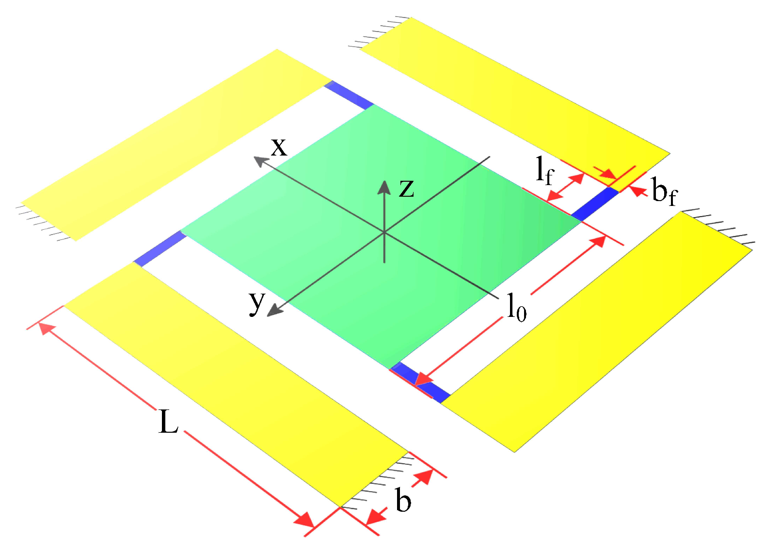
| Dimensional Parameters | Value (mm) |
|---|---|
| Length of the micro-actuator (L) | 11.3 |
| Width of the micro-actuator (b) | 2.5 |
| Thickness of the substrate layer () | 0.1 |
| Thickness of the PZT-5A () | 0.2 |
| Length of the flexure hinge () | 1.0 |
| Width of the flexure hinge () | 0.3 |
| Thickness of the flexure hinge () | 0.1 |
| Length of the center mirror () | 5.0 |
| Thickness of the center mirror () | 0.5 |
| Mechanical Properties | PZT-5A |
|---|---|
| Compliance of the PZT | Value |
| 16.40 | |
| −5.40 | |
| −7.22 | |
| 18.80 | |
| 47.50 | |
| 44.30 | |
| Piezoelectric strain coefficient | Value |
| 584 | |
| −171 | |
| 374 |
Publisher’s Note: MDPI stays neutral with regard to jurisdictional claims in published maps and institutional affiliations. |
© 2022 by the authors. Licensee MDPI, Basel, Switzerland. This article is an open access article distributed under the terms and conditions of the Creative Commons Attribution (CC BY) license (https://creativecommons.org/licenses/by/4.0/).
Share and Cite
Chen, N.; Liu, X. Dynamic Modeling and Attitude Decoupling Control for a 3-DOF Flexible Piezoelectric Nano-Positioning Stage Based on ADRC. Micromachines 2022, 13, 1591. https://doi.org/10.3390/mi13101591
Chen N, Liu X. Dynamic Modeling and Attitude Decoupling Control for a 3-DOF Flexible Piezoelectric Nano-Positioning Stage Based on ADRC. Micromachines. 2022; 13(10):1591. https://doi.org/10.3390/mi13101591
Chicago/Turabian StyleChen, Ning, and Xianfu Liu. 2022. "Dynamic Modeling and Attitude Decoupling Control for a 3-DOF Flexible Piezoelectric Nano-Positioning Stage Based on ADRC" Micromachines 13, no. 10: 1591. https://doi.org/10.3390/mi13101591