Optimization and Its Implementation Impact of Two-Modes Controller Fractional Approximation for Buck Converters
Abstract
:1. Introduction
2. Materials and Methods
2.1. DC-DC Buck Converter
2.2. Biquadratic Modules to Fractionally Approximate Laplacian Operator
2.3. Definition of Minimization Criteria: An Error-Based Approach
3. Results
3.1. Two-Modes Controller Structure
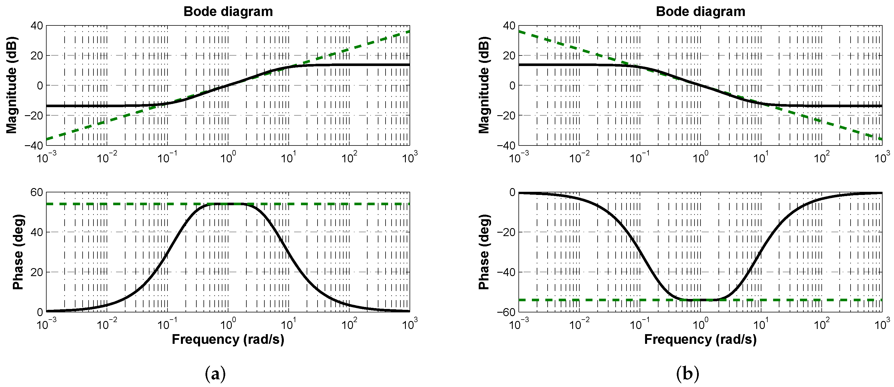
- If desired phase margin is , from it is deduced that controller phase contribution has to be °.
3.2. Numerical Results
- Particle swarm optimization algorithm (PS)
- Iterations: 600
- Population: 90
- Inertia coefficient w: 1
- Cognition constant : 2
- Social constant : 2
- Genetic optimization algorithm (GA)
- Iterations: 600
- Population: 90
- Mutation rate: 0.25
- Random recombination.
- Scale population coefficient: 1
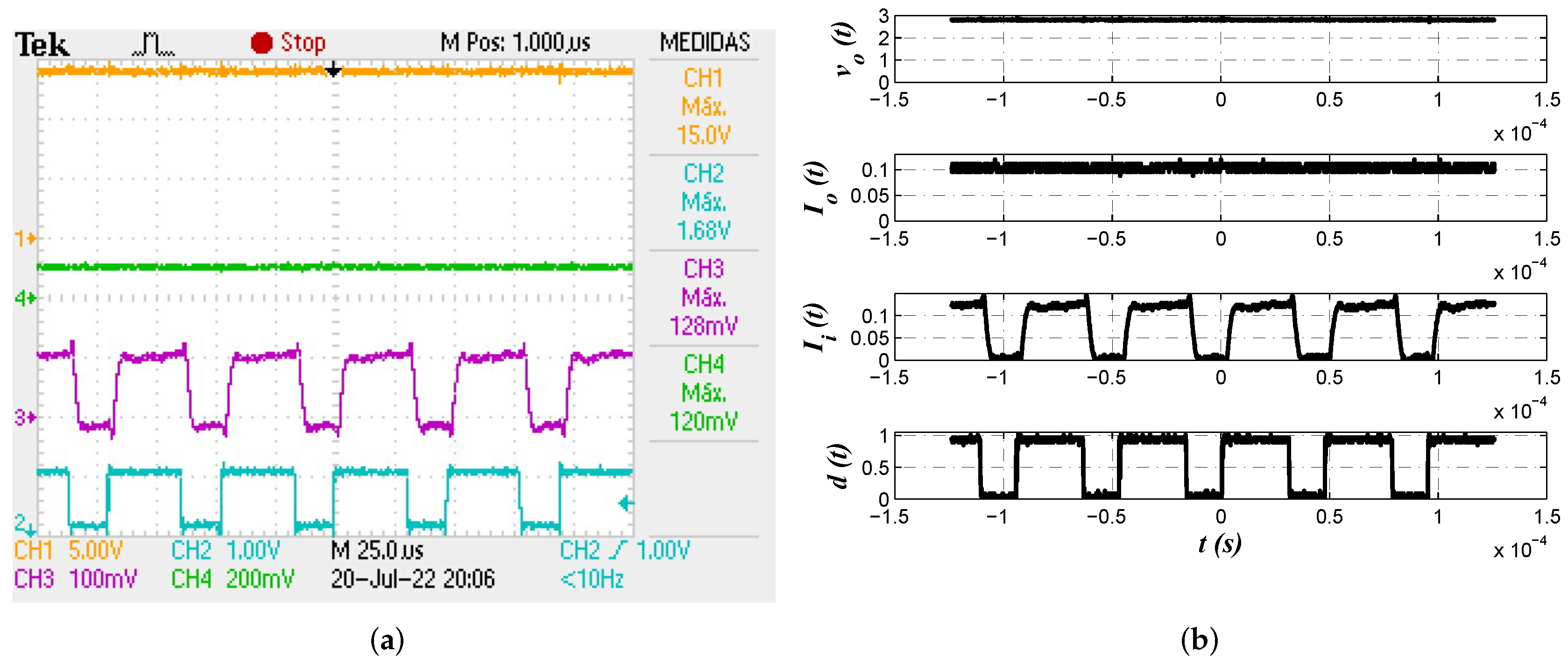
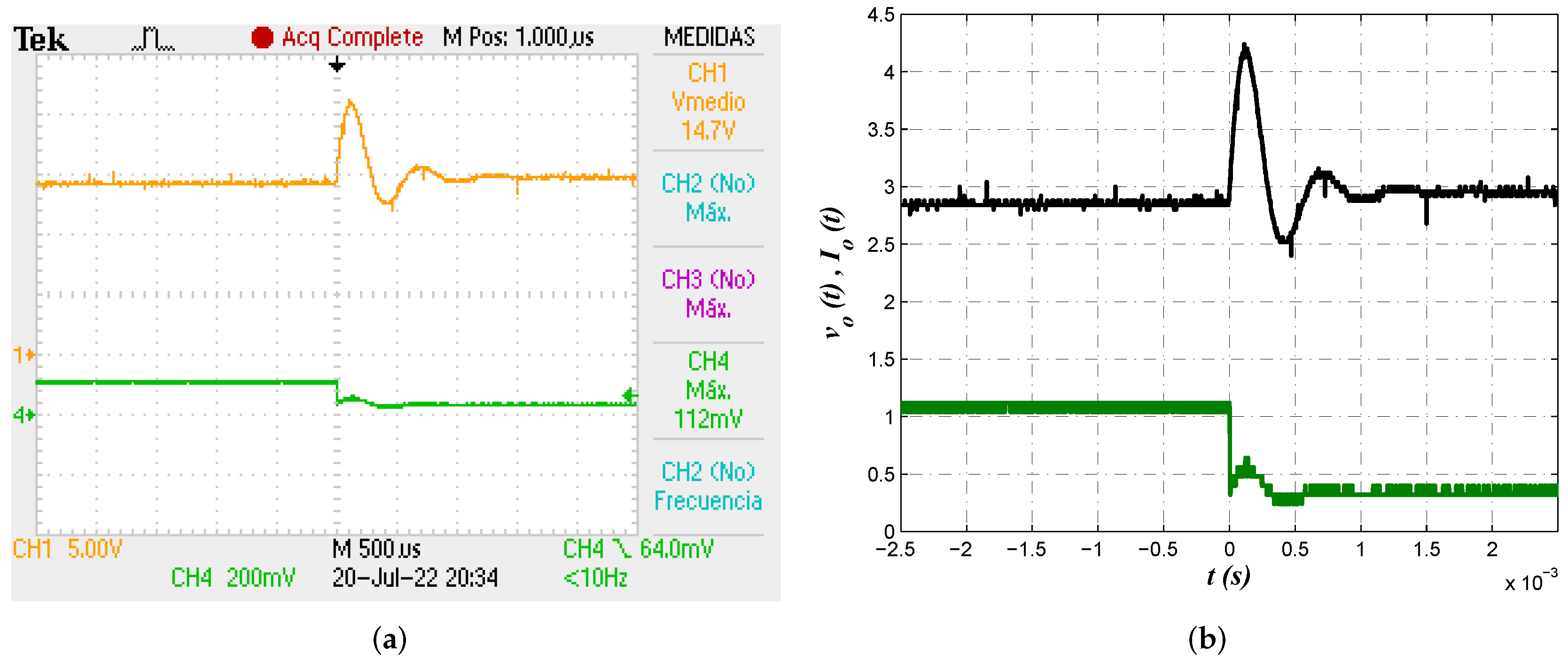
3.3. Experimental Results
4. Discussion
5. Conclusions
Author Contributions
Funding
Data Availability Statement
Acknowledgments
Conflicts of Interest
References
- Chandrakasan, A.P.; Verma, N.; Daly, D.C. Ultralow-power electronics for biomedical applications. Annu. Rev. Biomed. Eng. 2008, 10, 247–274. [Google Scholar] [CrossRef]
- Co, M.L.; Khouzam, J.P.; Pour-Ghaz, I.; Minhas, S.; Basu-Ray, I. Emerging technologies in cardiac pacing from leadless pacers to stem cells. Curr. Probl. Cardiol. 2021, 46, 100797. [Google Scholar] [CrossRef]
- Azimi, S.; Golabchi, A.; Nekookar, A.; Rabbani, S.; Amiri, M.H.; Asadi, K.; Abolhasani, M.M. Self-powered cardiac pacemaker by piezoelectric polymer nanogenerator implant. Nano Energy 2021, 83, 105781. [Google Scholar] [CrossRef]
- Adelstein, E.; Zhang, L.; Nazeer, H.; Loka, A.; Steckman, D. Increased incidence of electrical abnormalities in a pacemaker lead family. J. Cardiovasc. Electrophysiol. 2021, 32, 1111–1121. [Google Scholar] [CrossRef]
- Amara, Y.; Tebri, Z.; Larabi, Z. Design, Control, Management, and Performance Analysis of PV-Battery Supercapacitor DC-System Using Buck Converter. In Modeling and Control of Static Converters for Hybrid Storage Systems; IGI Global: Hershey, PA, USA, 2022; pp. 36–64. [Google Scholar]
- Awada, E.; Radwan, E.; Nour, M. Robust sliding mode controller for buck DC converter in off-grid applications. Bulletin Electr. Eng. Inform. 2022, 11, 2425–2433. [Google Scholar] [CrossRef]
- Abdurraqeeb, A.M.; Al-Shamma’a, A.A.; Alkuhayli, A.; Noman, A.M.; Addoweesh, K.E. RST Digital Robust Control for DC/DC Buck Converter Feeding Constant Power Load. Mathematics 2022, 10, 1782. [Google Scholar] [CrossRef]
- Alarcón-Carbajal, M.A.; Carvajal-Rubio, J.E.; Sánchez-Torres, J.D.; Castro-Palazuelos, D.E.; Rubio-Astorga, G.J. An Output Feedback Discrete-Time Controller for the DC-DC Buck Converter. Energies 2022, 15, 5288. [Google Scholar] [CrossRef]
- Sanchez, R.O.; Rumbo Morales, J.Y.; Ortiz Torres, G.; Pérez Vidal, A.F.; Valdez Resendiz, J.E.; Sorcia Vázquez, F.d.J.; Nava, N.V. Discrete State-Feedback Control Design with D-Stability and Genetic Algorithm for LED Driver Using a Buck Converter. Int. Trans. Electr. Energy Syst. 2022, 2022, 8165149. [Google Scholar] [CrossRef]
- Nizami, T.K.; Chakravarty, A.; Mahanta, C.; Iqbal, A.; Hosseinpour, A. Enhanced dynamic performance in DC–DC converter-PMDC motor combination through an intelligent non-linear adaptive control scheme. IET Power Electron. 2022, 1, 1–10. [Google Scholar] [CrossRef]
- Devaraj, S.V.; Gunasekaran, M.; Sundaram, E.; Venugopal, M.; Chenniappan, S.; Almakhles, D.J.; Subramaniam, U.; Bhaskar, M.S. Robust Queen Bee Assisted Genetic Algorithm (QBGA) Optimized Fractional Order PID (FOPID) Controller for Not Necessarily Minimum Phase Power Converters. IEEE Access 2021, 9, 93331–93337. [Google Scholar] [CrossRef]
- Mollaee, H.; Ghamari, S.M.; Saadat, S.A.; Wheeler, P. A novel adaptive cascade controller design on a buck–boost DC–DC converter with a fractional-order PID voltage controller and a self-tuning regulator adaptive current controller. IET Power Electron. 2021, 14, 1920–1935. [Google Scholar] [CrossRef]
- Aseem, K.; Kumar, S.S. Hybrid k-means Grasshopper Optimization Algorithm based FOPID controller with feed forward DC–DC converter for solar-wind generating system. J. Ambient Intell. Humaniz. Comput. 2021, 1, 1–24. [Google Scholar] [CrossRef]
- Tepljakov, A.; Alagoz, B.B.; Yeroglu, C.; Gonzalez, E.A.; Hosseinnia, S.H.; Petlenkov, E.; Ates, A.; Cech, M. Towards Industrialization of FOPID Controllers: A Survey on Milestones of Fractional-Order Control and Pathways for Future Developments. IEEE Access 2021, 9, 21016–21042. [Google Scholar] [CrossRef]
- Ghamari, S.M.; Narm, H.G.; Mollaee, H. Fractional-order fuzzy PID controller design on buck converter with antlion optimization algorithm. IET Control Theory Appl. 2022, 16, 340–352. [Google Scholar] [CrossRef]
- Karad, S.G.; Thakur, R. Fractional order controller based maximum power point tracking controller for wind turbine system. Int. J. Electron. 2022, 109, 875–899. [Google Scholar] [CrossRef]
- Paul, R. Fractional Order Modified AWPI Based DC-DC Converter Controlled SEDC Motor. In International Conference on Computational Techniques and Applications; Springer: Singapore, 2022; pp. 547–555. [Google Scholar]
- Saleem, O.; Shami, U.T.; Mahmood-ul Hasan, K. Time-optimal control of DC-DC buck converter using single-input fuzzy augmented fractional-order PI controller. Int. Trans. Electr. Energy Syst. 2019, 29, e12064. [Google Scholar] [CrossRef]
- Izci, D.; Hekimoğlu, B.; Ekinci, S. A new artificial ecosystem-based optimization integrated with Nelder-Mead method for PID controller design of buck converter. Alexandria Eng. J. 2022, 61, 2030–2044. [Google Scholar] [CrossRef]
- Izci, D.; Ekinci, S. A novel improved version of hunger games search algorithm for function optimization and efficient controller design of buck converter system. e-Prime Adv. Electr. Eng. Electron. Energy 2022, 2, 100039. [Google Scholar]
- Izci, D.; Ekinci, S.; Hekimoğlu, B. Fractional-order PID controller design for buck converter system via hybrid Lévy flight distribution and simulated annealing algorithm. Arab. J. Sci. Eng. 2022, 1, 1–19. [Google Scholar] [CrossRef]
- Mohadeszadeh, M.; Pariz, N.; Ramezani-al, M.R. A fractional reset control scheme for a DC-DC buck converter. Int. J. Dyn. Control 2022, 1, 1–12. [Google Scholar] [CrossRef]
- Jia, Z.; Liu, L.; Liu, C. Dynamic Analysis and Fractional-Order Terminal Sliding Mode Control of a Fractional-Order Buck Converter Operating in Discontinuous Conduction Mode. Int. J. Bifurc. Chaos 2022, 32, 2250045. [Google Scholar] [CrossRef]
- Sorouri, H.; Sedighizadeh, M.; Oshnoei, A.; Khezri, R. An intelligent adaptive control of DC–DC power buck converters. Int. J. Electr. Power Energy Syst. 2022, 141, 108099. [Google Scholar] [CrossRef]
- Cengelci, E.; Garip, M.; Elwakil, A.S. Fractional-order controllers for switching DC/DC converters using the K-factor method: Analysis and circuit realization. Int. J. Circuit Theory Appl. 2022, 50, 588–613. [Google Scholar] [CrossRef]
- Nirmala, R.J.; Balachandran, K.; Trujillo, J.J. Null controllability of fractional dynamical systems with constrained control. Fract. Calc. Appl. Anal. 2017, 20, 553–565. [Google Scholar] [CrossRef]
- Yaghooti, B.; Hosseinzadeh, M.; Sinopoli, B. Constrained control of semilinear fractional-order systems: Application in drug delivery systems. In Proceedings of the 2020 IEEE Conference on Control Technology and Applications (CCTA), Montreal, QC, Canada, 24–26 August 2020; pp. 833–838. [Google Scholar]
- Sopasakis, P.; Sarimveis, H. Stabilising model predictive control for discrete-time fractional-order systems. Automatica 2017, 75, 24–31. [Google Scholar] [CrossRef]
- De Oliveira, E.C.; Tenreiro Machado, J.A. A review of definitions for fractional derivatives and integral. Math. Probl. Eng. 2014, 2014, 1–6. [Google Scholar] [CrossRef]
- Carlson, G.; Halijak, C. Approximation of fractional capacitors (1/s)ˆ(1/n) by a regular Newton process. IEEE Trans. Circuits Theory 1964, 11, 210–213. [Google Scholar] [CrossRef]
- Oustaloup, A.; Levron, F.; Mathieu, B.; Nanot, F.M. Frequency-band complex noninteger differentiator: Characterization and synthesis. IEEE Trans. Circuits Syst.-I Fundam. Theory Appl. 2000, 47, 25–39. [Google Scholar] [CrossRef]
- Monje, C.A.; Chen, Y.; Vinagre, B.M.; Xue, D.; Feliu-Batlle, V. Fractional-Order Systems and Controls: Fundamentals and Applications; Springer Science & Business Media: Berlin/Heidelberg, Germany, 2010. [Google Scholar]
- Charef, A.; Sun, H.; Tsao, Y.; Onaral, B. Fractal system as represented by singularity function. IEEE Trans. Autom. Control 1992, 37, 1465–1470. [Google Scholar] [CrossRef]
- El-Khazali, R. Fractional–order PIλDμ controller design. Comput. Math. Appl. 2013, 66, 639–646. [Google Scholar] [CrossRef]
- El-Khazali, R. On the biquadratic approximation of fractional–order Laplacian operators. Analog Integr. Circuits Signal Process. 2015, 82, 503–517. [Google Scholar] [CrossRef]
- Erickson, R.W.; Maksimovic, D. Fundamentals of Power Electronics; Springer Science & Business Media: Berlin/Heidelberg, Germany, 2007. [Google Scholar]
- Rana, N.; Latiff, M.S.A.; Abdulhamid, S.M.; Chiroma, H. Whale optimization algorithm: A systematic review of contemporary applications, modifications and developments. Neural Comput. Appl. 2020, 32, 16245–16277. [Google Scholar] [CrossRef]
- Mirjalili, S.; Lewis, A. The whale optimization algorithm. Adv. Eng. Softw. 2016, 95, 51–67. [Google Scholar] [CrossRef]
- Åström, K.J.; Murray, R.M. Feedback Systems: An Introduction for Scientists and Engineers; Princeton University Press: Princeton, NJ, USA, 2021. [Google Scholar]
- Kochenderfer, M.J.; Wheeler, T.A. Algorithms for Optimization; Mit Press: Cambridge, MA, USA, 2019. [Google Scholar]



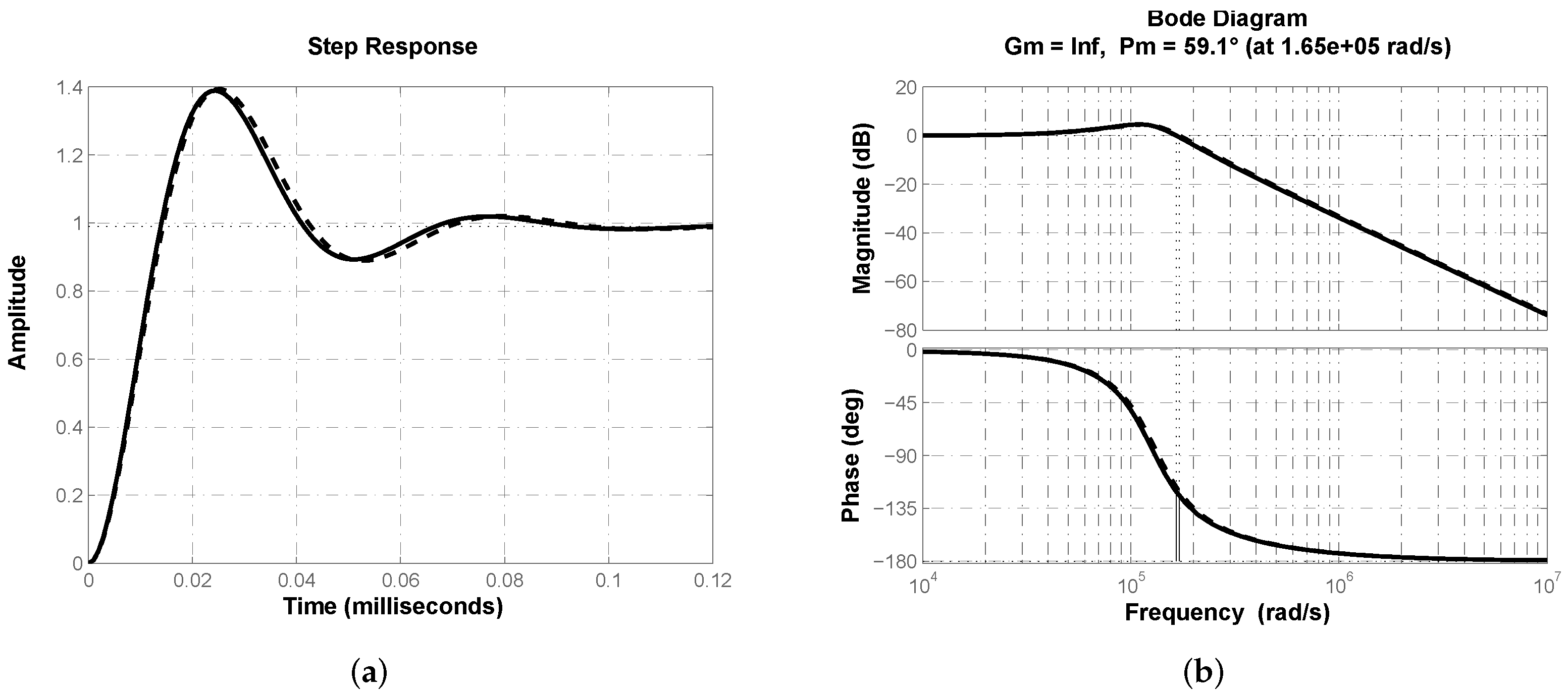

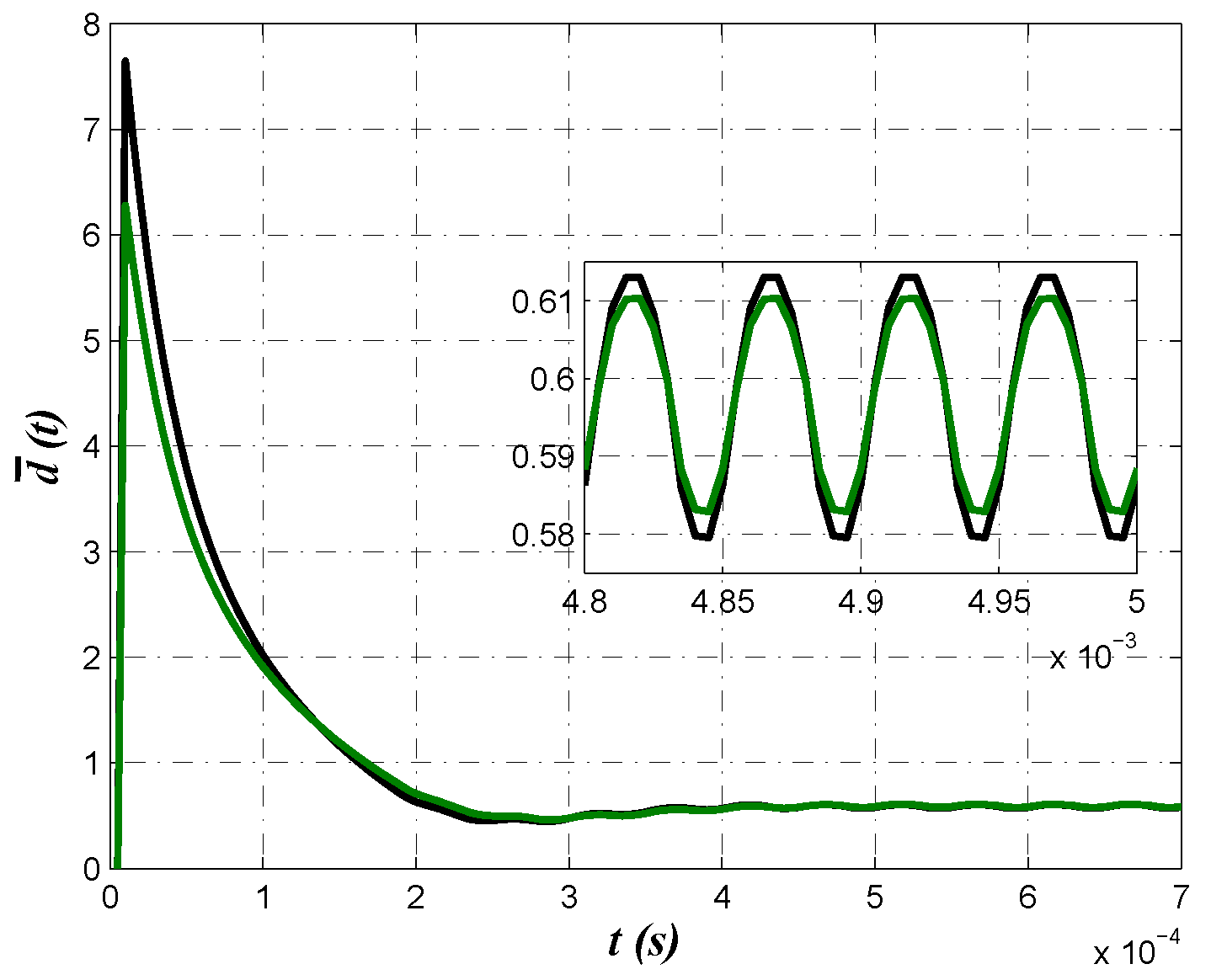
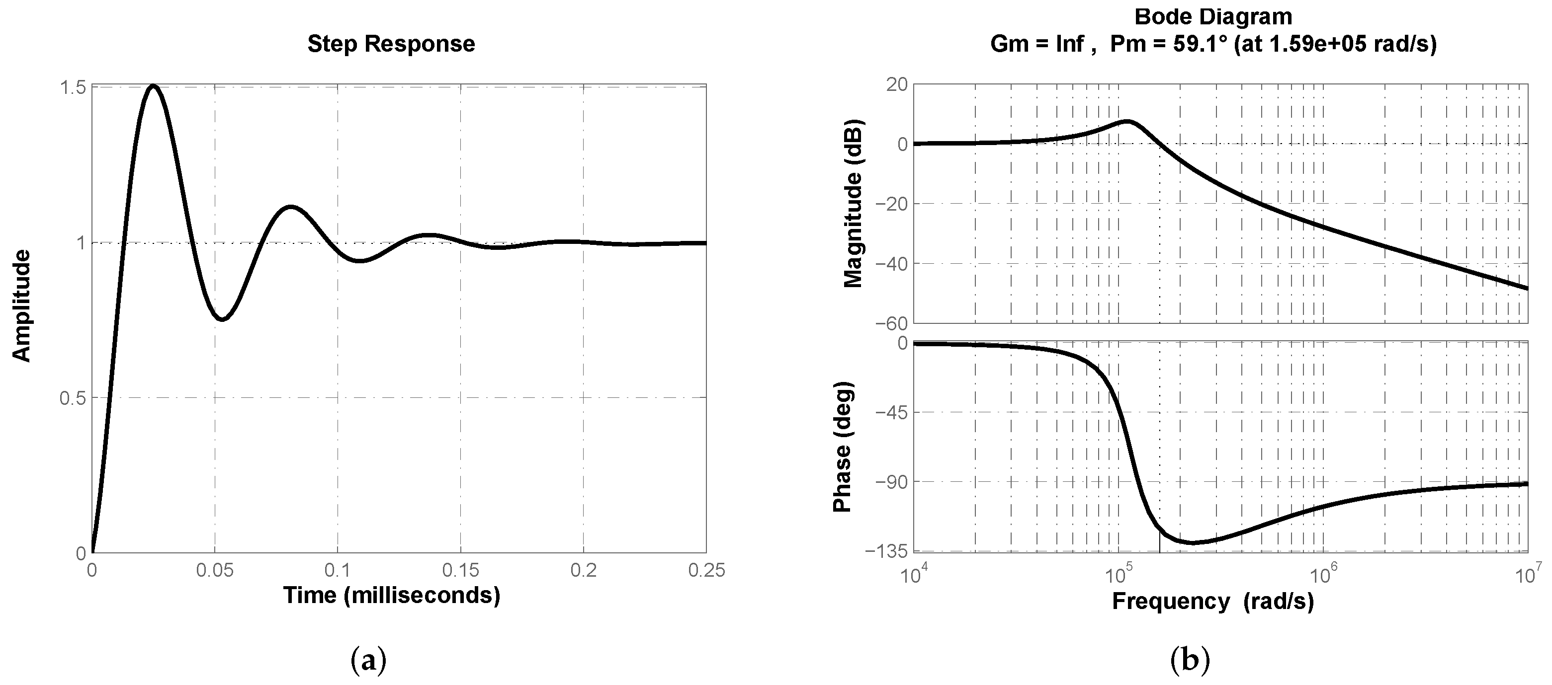
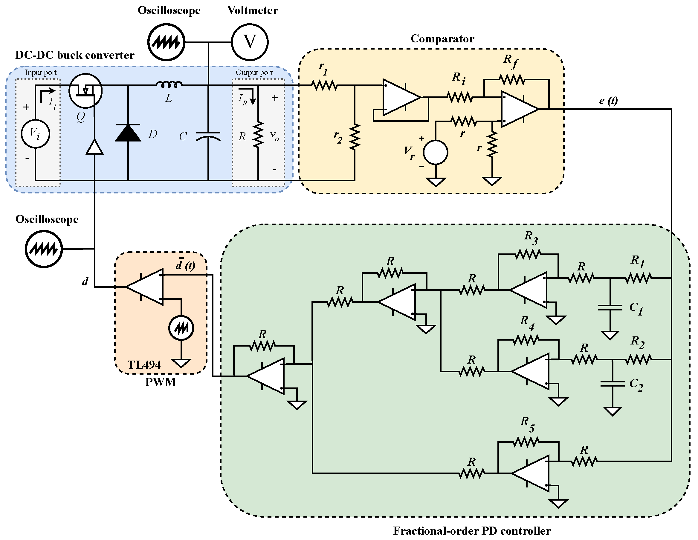

| Component/Element | Notation | Value | Generals |
|---|---|---|---|
| Capacitor | C | 7 F | C4AQCBU4700A1YJ, 650 V, ±5% |
| Inductor | L | 2.7 mH | 1140-272K-RC, 555 m, 2.2/3.9 A, ±10% |
| Resistance | R | 10 | CB25JB10R0, 25 W, ±5% |
| Power supply | 25 V | Programmable BK Precision 9129B | |
| MOSFET | Q | PSMN022-30PL, N-Ch, 30 V , 22 m, 30 A | |
| Diode | D | MUR840, 50–600 V, 8 A, 1 V | |
| MOSFET driver | Optocoupler TLP250 | ||
| Switching frequency | 20 kHz |
| GA | 0.4148 | 1.2839 | 4.9995 | 0.4148 | 1.9331 | 2.5497 |
| 0.4148 | 1.2847 | 4.9995 | 0.4148 | 1.9225 | 2.5553 | |
| 0.4148 | 1.2842 | 4.9995 | 0.4148 | 1.7595 | 3.0316 | |
| 0.4148 | 1.2851 | 4.9994 | ||||
| 0.4148 | 1.2856 | 4.9927 | ||||
| 0.4148 | 1.2844 | 4.9989 | ||||
| PS | 0.4148 | 1.2851 | 5 | 0.4148 | 1.8759 | 2.7445 |
| 0.4148 | 1.2852 | 5 | 0.4148 | 1.8773 | 2.7404 | |
| 0.4148 | 1.2854 | 5 | 0.4148 | 1.8733 | 2.7522 | |
| 1/2 | 3/4 | 1/ 2 | 3/ 4 | |||
|---|---|---|---|---|---|---|
| GA | 7.461/6.739 | 1.813/3.46 | 18.7218 | 8.121/8.461 | 1.813/3.46 | 15.3230 |
| 7.461/6.739 | 1.813/3.46 | 18.7334 | 8.118/8.454 | 1.813/3.46 | 15.2683 | |
| 7.461/6.739 | 1.813/3.46 | 18.7261 | 7.916/7.926 | 1.813/3.46 | 16.2504 | |
| 7.461/6.739 | 1.813/3.46 | 18.7389 | ||||
| 7.462/6.741 | 1.813/3.46 | 18.7228 | ||||
| 7.461/6.739 | 1.813/3.46 | 18.7270 | ||||
| PS | 7.461/6.739 | 1.813/3.46 | 18.7410 | 8.03/8.225 | 1.813/3.46 | 15.8624 |
| 7.461/6.739 | 1.813/3.46 | 18.7425 | 8.032/8.229 | 1.813/3.46 | 15.8533 | |
| 7.461/6.739 | 1.813/3.46 | 18.7454 | 8.027/8.216 | 1.813/3.46 | 15.8796 | |
| / | / | |||
|---|---|---|---|---|
| GA | 13.78/101.54 | 12.11/2.96/18.72 | 13.78/101.54 | 9.30/2.28/15.32 |
| 13.78/101.54 | 12.12/2.97/18.73 | 13.78/101.54 | 9.27/2.27/15.27 | |
| 13.78/101.54 | 12.12/2.96/18.73 | 13.78/101.54 | 10.07/2.46/16.25 | |
| 13.78/101.54 | 12.12/2.97/18.74 | |||
| 13.78/101.54 | 12.11/2.96/18.72 | |||
| 13.78/101.54 | 12.12/2.96/18.73 | |||
| PS | 13.78/101.54 | 12.13/2.97/18.74 | 13.78/101.54 | 9.72/2.38/15.86 |
| 13.78/101.54 | 12.13/2.97/18.74 | 13.78/101.54 | 9.71/2.38/15.85 | |
| 13.78/101.54 | 12.13/2.97/18.75 | 13.78/101.54 | 9.7/2.38/15.87 | |
| Optimization results | ||||||
| GA | 0.9936 | 29.728 | 29.8142 | 0.975 | 29.9437 | 7.8793 |
| 0.9936 | 29.9927 | 29.9945 | 0.9396 | 29.9912 | 3.2028 | |
| 0.9937 | 29.9999 | 29.9975 | 0.846 | 29.9346 | 1.2147 | |
| 0.9937 | 29.9931 | 29.9971 | 0.8917 | 29.9948 | 1.7824 | |
| 0.9936 | 30 | 29.9904 | 0.9762 | 29.9868 | 8.4766 | |
| 0.9936 | 29.9959 | 29.9357 | 0.9489 | 29.978 | 3.9742 | |
| PS | 0.9937 | 30 | 30 | 0.8847 | 30 | 1.7319 |
| 0.8843 | 30 | 1.7255 | ||||
| 0.8786 | 30 | 1.607 | ||||
| 0.8889 | 30 | 1.8075 | ||||
| Controller coefficients | ||||||
| 1/ 2 | 2/ 3 | 1 | 1/2 | 4/ 5 | 6 | |
| GA | 3.717/4.545 | 1.674/5.925 | 41.241 | 4.142/17.24 | 42.9/14.85 | 27.534 |
| 3.717/4.519 | 1.674/5.925 | 41.859 | 5.005/42.22 | 17.79/5.901 | 4.4812 | |
| 3.716/4.514 | 1.7/6.02 | 42.543 | 7.426/107.2 | 7.007/2.086 | 0.6255 | |
| 3.716/4.514 | 1.7/6.02 | 42.533 | 6.197/74.93 | 9.946/3.119 | 1.3394 | |
| 3.717/4.52 | 1.674/5.925 | 41.864 | 4.104/16.05 | 45.05/15.62 | 31.198 | |
| 3.717/4.527 | 1.674/5.925 | 41.782 | 4.731/34.19 | 21.02/7.049 | 6.6248 | |
| PS | 3.716/4.514 | 1.7/6.02 | 42.547 | 6.298/77.16 | 9.345/2.907 | 1.2161 |
| 6.309/77.43 | 9.313/2.896 | 1.2071 | ||||
| 6.5/82.77 | 8.878/2.742 | 1.0682 | ||||
| 6.184/74.08 | 9.697/3.031 | 1.3206 | ||||
| Controller component values | ||||||
| / | / | |||||
| GA | 0.13/62.01 | 412.364/10.19/412.405 | 0.52/63.05 | 27.491/10.38/27.534 | ||
| 0.13/62.01 | 418.551/10.34/418.594 | 1.26/65.07 | 4.439/9.81/4.481 | |||
| 0.13/62 | 425.389/10.18/425.432 | 3.29/70.62 | 0.585/8.52/0.626 | |||
| 0.13/62 | 425.287/10.18/425.329 | 2.29/67.87 | 1.298/9.28/1.339 | |||
| 0.13/62.01 | 418.596/10.34/418.638 | 0.49/62.98 | 31.156/10.66/31.198 | |||
| 0.13/62.01 | 417.775/10.32/417.818 | 1.06/64.54 | 6.582/10.41/6.625 | |||
| PS | 0.13/62 | 425.426/10.18/425.468 | 2.44/68.29 | 1.174/9.53/1.216 | ||
| 2.45/68.31 | 1.165/9.52/1.207 | |||||
| 2.57/68.65 | 1.027/9.24/1.068 | |||||
| 2.35/68.04 | 1.279/9.63/1.321 | |||||
| Optimization results | ||||
| GA | 9.9988 | 2.98 | 9.9993 | 2.85 |
| 9.9983 | 2.98 | 9.999 | 2.95 | |
| PS | 10 | 2.99 | 10 | 2.95 |
| 10 | 2.98 | 10 | 2.97 | |
| Controller component values | ||||
| / | / | |||
| GA | 1 k/9.9 k | 1 F/2.98 | 1 k/9.9 k | 1 F/2.85 |
| 1 k/9.9 k | 1 F/2.98 | 1 k/9.9 k | 1 F/2.95 | |
| PS | 1 k/10 k | 1 F/2.99 | 1 k/10 k | 1 F/2.95 |
| 1 k/10 k | 1 F/2.98 | 1 k/10 k | 1 F/2.97 | |
Publisher’s Note: MDPI stays neutral with regard to jurisdictional claims in published maps and institutional affiliations. |
© 2022 by the authors. Licensee MDPI, Basel, Switzerland. This article is an open access article distributed under the terms and conditions of the Creative Commons Attribution (CC BY) license (https://creativecommons.org/licenses/by/4.0/).
Share and Cite
S. Sánchez, A.G.; Perez-Pinal, F.-J.; Espinosa-Calderón, A. Optimization and Its Implementation Impact of Two-Modes Controller Fractional Approximation for Buck Converters. Micromachines 2022, 13, 1600. https://doi.org/10.3390/mi13101600
S. Sánchez AG, Perez-Pinal F-J, Espinosa-Calderón A. Optimization and Its Implementation Impact of Two-Modes Controller Fractional Approximation for Buck Converters. Micromachines. 2022; 13(10):1600. https://doi.org/10.3390/mi13101600
Chicago/Turabian StyleS. Sánchez, Allan G., Francisco-Javier Perez-Pinal, and Alejandro Espinosa-Calderón. 2022. "Optimization and Its Implementation Impact of Two-Modes Controller Fractional Approximation for Buck Converters" Micromachines 13, no. 10: 1600. https://doi.org/10.3390/mi13101600
APA StyleS. Sánchez, A. G., Perez-Pinal, F.-J., & Espinosa-Calderón, A. (2022). Optimization and Its Implementation Impact of Two-Modes Controller Fractional Approximation for Buck Converters. Micromachines, 13(10), 1600. https://doi.org/10.3390/mi13101600


