Article

Hydrodynamics of Droplet Sorting in Asymmetric Acute Junctions

1
School of Mechanical Engineering, Hangzhou Dianzi University, No. 2 Street, Qiantang District, Hangzhou 310018, China
2
Yusuf Hamied Department of Chemistry, University of Cambridge, Lensfield Road, Cambridge CB2 1EW, UK
3
Cavendish Laboratory, University of Cambridge, JJ Thomson Avenue, Cambridge CB3 0HE, UK
*
Author to whom correspondence should be addressed.
Micromachines 2022, 13(10), 1640; https://doi.org/10.3390/mi13101640
Submission received: 19 August 2022 / Revised: 16 September 2022 / Accepted: 27 September 2022 / Published: 29 September 2022
(This article belongs to the Special Issue Droplet Microfluidics: Fundamentals and Its Advanced Applications)

Abstract

:
Droplet sorting is one of the fundamental manipulations of droplet-based microfluidics. Although many sorting methods have already been proposed, there is still a demand to develop new sorting methods for various applications of droplet-based microfluidics. This work presents numerical investigations on droplet sorting with asymmetric acute junctions. It is found that the asymmetric acute junctions could achieve volume-based sorting and velocity-based sorting. The pressure distributions in the asymmetric junctions are discussed to reveal the physical mechanism behind the droplet sorting. The dependence of the droplet sorting on the droplet volume, velocity, and junction angle is explored. The possibility of the employment of the proposed sorting method in most real experiments is also discussed. This work provides a new, simple, and cost-effective passive strategy to separate droplets in microfluidic channels. Moreover, the proposed acute junctions could be used in combination with other sorting methods, which may boost more opportunities to sort droplets.

1. Introduction

Droplet-based microfluidics has received increasing interest over the recent two decades, due to the large amount of applications in chemical reactions [1,2], materials synthesis [3,4], protein engineering [5,6,7,8], drug discovery [9,10,11], and single-cell analysis [12]. As one of fundamental operations in droplet-based microfluidics, droplet sorting based on various contents is used to achieve the enrichment, isolation, and quantitative analysis of the samples. The ability to sort droplets is of crucial importance to chemical and biological applications, such as microreactors [13], drug screening [14,15], and cell encapsulation [16]. Therefore, there is an enormous demand to rationally design and develop sorting methodology for the vast applications of the droplet-based microfluidics.
Many methods have been proposed to achieve droplet sorting in the droplet-based microfluidics, both actively and passively. The active sorting methods mainly include electrical sorting, acoustic method, magnetic control, pneumatic actuators, and thermal methods [17,18]. The electric sorting uses electric forces to push or pull droplets with charges. The early attempt of using electric control was made by Link et al. [19]; the droplets are sorted into the collective channel under the effect of electrostatic forces caused by the direct current. In this method, pre-charged droplets are required before they are sorted, which can be realized by exposing the droplets to energized electrodes [20,21] or deploying the induction effect of electric fields [22,23]. Another electric method for droplet sorting is based on the dielectrophoresis effect of alternating current, which produces dielectric forces on the droplets [24,25,26,27]. Electric control usually requires a high voltage to activate the electrodes [13,20,27]. Acoustic sorting is based on the acoustic streaming or acoustic radiation forces impacting on the droplets. Three kinds of acoustic modes are developed to sorting the droplets, including travelling surface acoustic [28,29,30], standing surface acoustic wave [31,32,33,34], and bulk acoustic wave [35]. Although the acoustic methods have good sensitivity, accuracy, throughput, contactless operation, and biocompatibility, they require expensive equipment to operate, including function generators, voltage amplifiers, signal processors, and acoustic transducers [36]. Magnetic sorting is based on the magnetic forces on the droplets exerted by electromagnet or permanent magnet. Usually, ferrofluid, magnet particles, or beads are used in the continuous phase or dispersed phase to fulfil magnet sorting [37,38,39,40]. The drawback of the magnetic sorting is that the required magnetic materials limit their biological or chemical applications. It is impossible to remove the magnetic labels for downstream analysis and the labels may change the properties of the cells [18]. Pneumatic sorting uses the deformation of the microchannels or microvalves to adjust the hydrodynamic pressure or resistance [41,42]. The pneumatic methods have a good flexibility of droplet size, channel geometry, chemical formulation, and biocompatibility but relatively low durability and throughput [17]. Thermal sorting is based on the thermocapillary effect produced by additional resistive heating [43] or focused laser heating [44]. The thermocapillary forces and the change in the fluid viscosity and interfacial tension deflect the droplets to the collective channels, achieving droplet sorting [17,45]. The predominant advantage of active sorting methods is that they can realize on-demand control of the droplet when incorporating the detection methods. However, these methods require additional energy input and the complex structure of the active sorting would increase the fabrication difficulty and the cost, especially for those high-throughput chips containing hundreds and thousands of microfluidic channels.
Passive sorting methods have the advantages of easy fabrication, low cost, biocompatibility, and no requirement of external control components. In principle, the passive droplet sorting usually adopts the hydrodynamic features to manipulate the droplets [46]. Many passive methods have been proposed over the last two decades, including grooves [47,48], inertial microfluidics [49], deterministic lateral displacement [50], and microscale filters [51]. Droplet sorting with groove rails is based on the Laplace pressure. When the droplets encounter the parallel rails, they are trapped and follow the rail path. The small droplet is maintained in the old grooves, while the large droplets are transferred to new rails under Laplace pressure [52]. The inertial microfluidics uses the inertial lift forces to separate the droplets. Specifically, droplets of different sizes or deformability have different lateral equilibrium positions under the lift forces [53,54]. The averaged lateral position of the large droplet is closer to the channel centreline than that of the small one [49]. The deterministic lateral displacement relies on the hydrodynamic forces. The droplets of various sizes or deformability displace differently in the lateral direction [55,56,57,58]. The microscale filters separate droplets based on the size exclusion [51]. The size of the passive filter needs to be precisely controlled to filter the desired droplets. Although these passive methods have already been investigated, new passive methods are still required to be developed to achieve the simple, cost-effective, high-throughput, and precise sorting of the droplets for extensive biochemical applications.
Asymmetric microchannels have attracted the interest of many researchers, due to their unique manipulation of the droplet breakup. A simple asymmetric junction can be achieved by varying the length or width of the T junction [59]. This asymmetric T junction is used for producing unequal-sized daughter droplets. The length ratio of the daughter droplets depends on the capillary number, initial droplet length, length ratio, and width ratio of the branching channels [60,61,62]. Another kind of asymmetric junction is that the bifurcating channels are intersected with a non-rectangular angle. Ménétrier-Deremble and Tabeling [63] examined droplet breakup behavior in the asymmetric junctions with an angle of 45° and 135°. Both direct and retarded breakup process were observed. The breakup behavior is strongly affected by the channel geometry. Wang et al. [64] investigated an asymmetric splitting junction, in which two channels are intersected with an angle of 30°. The splitting ratio of daughter droplets is largely affected by the initial droplet length and the velocity. Although a number of studies are reported to explore the droplet flow in asymmetric microchannels, they mainly focus on the asymmetric splitting of the droplets, rather than droplet sorting behavior.
In this work, we investigate whether the droplet sorting can be achieved using asymmetric acute junctions. Both volume-based and velocity-based sorting are numerically investigated using the volume of fluid (VOF) model. The effect of junction angle on the sorting behavior is explored in detail. The angle of the acute junction varies from 20° to 80°. The numerical details are described in Section 2. Section 3 presents the volume-based and velocity-based sorting and then a phase regime of the droplet sorting is presented to illustrate the dependence of the sorting behavior on the junction angle, droplet volume, and droplet velocity. Section 4 discusses whether the proposed sorting method can be used in most real applications of droplet-based microfluidics. Finally, the main conclusions are drawn in Section 4.

2. Numerical Details

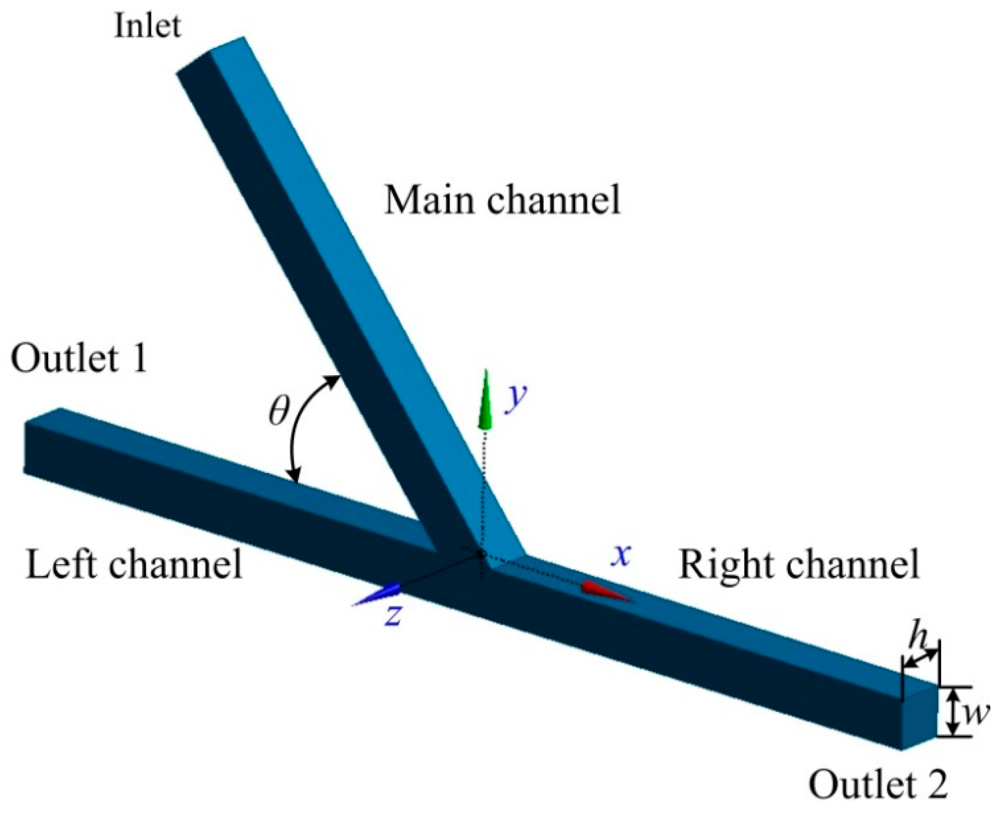
2.1. Geometry of the Asymmetric Acute Junction

The geometry of the asymmetric microfluidic junction includes the main, left, and right channels, as shown in Figure 1. The main and left channels are intersected with an acute angle θ, while the left and right channel are aligned. All three channels have a width of w = 100 μm and a depth of h = 100 μm. The main channel has a length of Lm = 11 w, while the two branching channels have the same length of LL = LR = 10.5 w. The numerical results shows that these dimensions are long enough to obtain an equilibrium of the droplet shape before arriving at the acute junction. Water-in-oil droplets were investigated in this work, that is, the droplet fluid and the medium fluid were set to water and oil, respectively. Following previous work conducted by Hoang et al. [65], the viscosity and density of the water droplet were μd = 1 × 10⁻³ Pa·s and of ρd = 1000 kg/m3, respectively. The medium oil fluid had a viscosity of μm = 8 × 10⁻³ Pa·s and a density of ρm = 770 kg/m3. The interfacial tension between the medium fluid and droplet fluid was σ = 5 × 10⁻³ N/m. The velocity U of the main channel varied from 4 × 10⁻³ to 4 × 10⁻² m/s, and the corresponding capillary number was Ca = μmU/σ = 6.4 × 10⁻³–6.4 × 10⁻². The capillary number represents the relative effect of viscous force versus surface tension. The non-dimensional volume of the droplet was within the range of Vd/w3 = 0.5–2.5.

2.2. Governing Equations

In this work, we used the volume of fluid (VOF) model [66] to simulate the interface between the droplet and the medium fluid, which has been successfully applied to modelling various droplet flows (e.g., Refs. [67,68,69]). The VOF model is a numerical method for modelling the liquid–liquid interface. It is based on the use of a fractional function C, which is defined as an integral of the characteristic functions of the fluid in a computational grid cell. C is a continuous function, with 0 ≤ C ≤ 1. If the cell is empty of the tracked fluid, C = 0. If the cell is full of tracked fluid, C = 1. Additionally, if the cell contains an interface between the tracked and non-tracked fluids, 0 < C < 1. The governing equations for the droplet flow in microfluidic channel consist of a continuity equation and momentum equation, which can be expressed as follows,
ρ t + ( ρ u ) = 0
( ρ u ) t + ( ρ u u ) = p + [ μ ( u + ( u ) T ) ] + ρ g + F s
where p is the pressure, and ρ and μ represent the density and viscosity of the two-phase fluids, respectively. Fs denotes the surface tension force obtained by the continuum surface force (CSF) model [70]. The density, viscosity, and surface tension force of the two-phase fluids can be calculated by
ρ = α d ρ d + α m ρ m
μ = α d μ d + α m μ m
F s = γ ρ κ d α d 1 2 ( ρ c + ρ d )
where ρd and ρm represent the fluid density of the droplet and medium phase, respectively. μd and μc denote the fluid viscosity of the droplet and medium phase, respectively. αd and αm are the volume fraction of the droplet and medium phase, respectively. αd + αm =1. κd is the curvature of the phase interface.
The numerical simulations were conducted using commercial software Fluent 17.0. The transient laminar flow and VOF model were used for the calculations of the governing equations. Velocity-inlet and pressure-outlet boundary conditions were applied for the inlet of the main channel and the outlets of the left and right channels, respectively. A no-slip stationary boundary condition was employed at the walls, which were assumed to be super hydrophobic with a contact angle of 180°, as was conducted in Refs [65,67]. The SIMPLEC method was used to calculate the pressure–velocity coupling, due to the less convergence time [60,71]. Following previous studies (e.g., Refs. [67,68,69]), the Geo-Reconstruct scheme was chosen to solve the volume fraction of the two immiscible fluids and the PRESTO! algorithm was applied to calculate the pressure term. The second order upwind scheme was used to calculate the momentum term. The grid independence study was performed, which shows that the grid size of Lgrid = 1/30 w, where w is the channel width, was enough to obtain the satisfactory results. Numerical simulations were conducted on a workstation (Intel®Xeon® Platinum 8358P with dual processors, 32 cores, and 256 GB RAM). The computation time for each run was approximately 2 to 4 days, which varied at different inlet velocity.

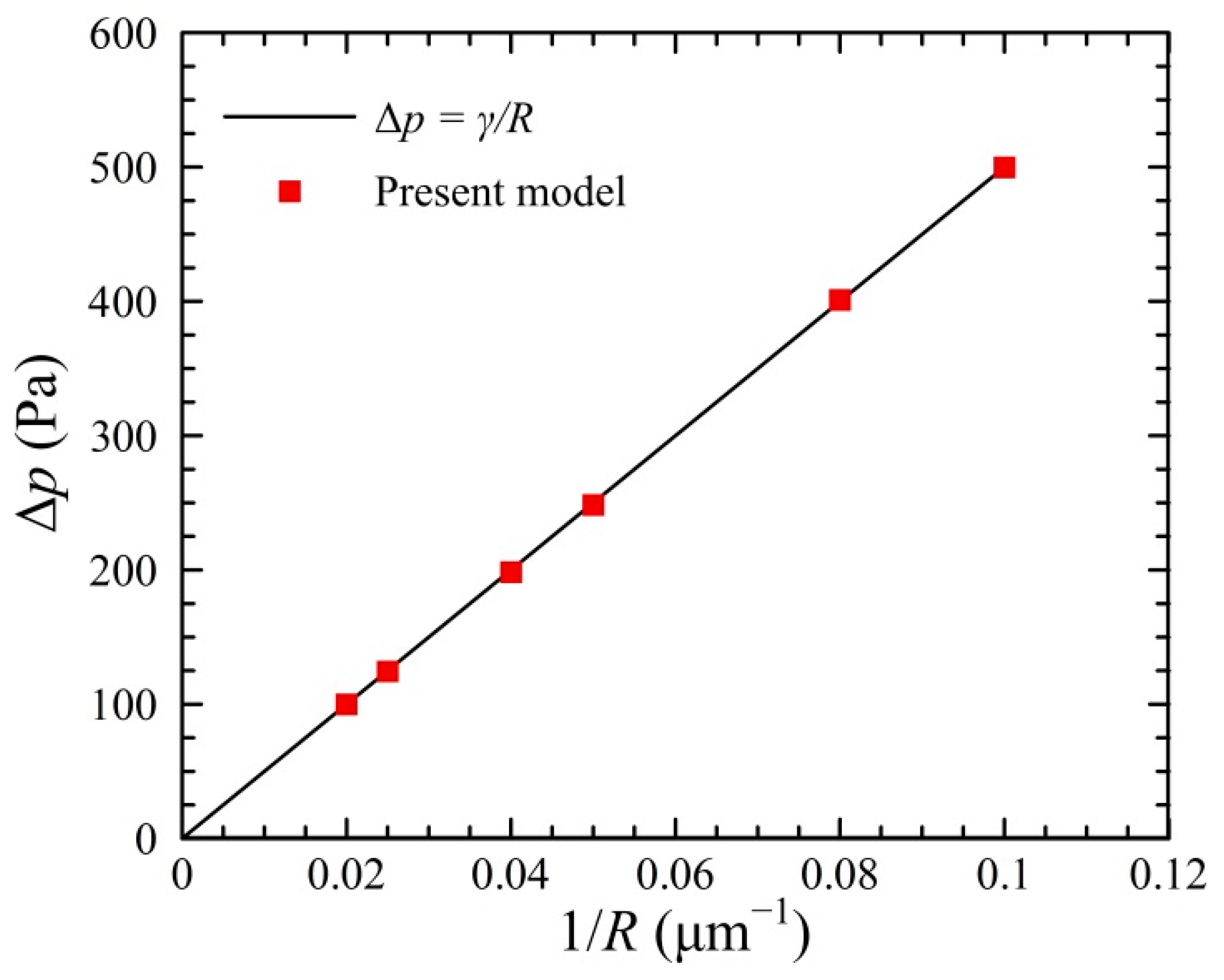
2.3. Model Validation

Previous studies (e.g., Ref. [65]) have successfully proven that VOF model can be used to simulate the droplet formation and breakup in microfluidic channel. In this work, the numerical model was further validated by examining the Laplace’s law and Taylor deformation of the droplet in microfluidic channels, as was conducted in Ref. [72].
We first validated our model by examining the Laplace’s law. A circular water droplet was located at the center of a square oil domain with the size of 256 μm × 128 μm. The mesh had a grid size of Δ = 1 μm. No slip stationary wall conditions were applied to all boundaries. In this simulation, the water had a density of ρw = 1000 kg/m3 and a viscosity of μw = 1 × 10⁻³ Pa·s, while the oil had a density of ρd = 1000 kg/m3 and a viscosity of μo = 8 × 10⁻³ Pa·s. The interfacial tension of two fluid was γ = 5 × 10⁻³ N/m. The pressure difference Δp across the droplet interface in the equilibrium state was provided by the Laplace’s law Δp = γ/R, where R denotes the droplet radius. It can be observed from Figure 2 that the pressure difference Δp exhibits a linear relationship with the 1/R, and the numerical results of present model agree well with those calculated by the Laplace’s law. This indicates that the present model is acceptable for predicting the droplet size in the microchannel.
To further validate the numerical model, a three-dimensional (3D) deformation of the droplet in a simple shear flow was examined. In this case, the computational domain had a length of Ls = 128 μm and a width and a height of Ws = Hs = 62 μm. The initial diameter of the droplet was set to be Di = 20 μm. The density and the viscosity of droplet and medium fluids were ρd = ρm = 1000 kg/m3 and μd = μm = 1 × 10⁻³ Pa·s. The capillary number Ca varied from 0 to 0.03. The three-dimensional deformation D of a droplet in a simple shear flow was calculated using the Taylor deformation number [73],
D = L B L + B = 19 μ d + 16 μ m 16 μ d + 16 μ m = 35 32 C a
where L and B denote the major and minor axes of the deformed droplet, respectively.
Figure 3 presents the dependence of droplet deformation in the shear flow on the capillary number. The results of droplet deformation simulated by the Lattice Boltzmann method (LBM) [73] are shown for the comparison. It can be observed that the present results agree well with those obtained by the theoretical prediction and the LBM. This indicates that present model can be used for the modelling of the deformed droplet within a satisfactory accuracy.

3. Results

3.1. Volume-Based Droplet Sorting

The asymmetric microfluidic junction with an acute angle between the main channel and the branching channel can be used for volume-based droplet sorting. Large droplets are sorted into the left channel, while small droplets enter into the right channel. Both the subsequent stages of the droplet sorting and corresponding pressure distributions are examined in this section.
Figure 4 shows the subsequent stages of large droplet sorting into the left channel of the asymmetric junction. The time propagates from T0 to T5, with the time intervals rescaled by w/U. The angle of the asymmetric junction was fixed at θ = 50°. The non-dimensional volume of the droplet was Vd/w3 = 0.85 and the inlet velocity as fixed at U = 20 mm/s, with the corresponding capillary number of Ca = 0.032. Initially, the droplet starts to move into the junction at the time of T0. At T1, the droplet enters into the junction earlier at the left side than at the right side, due to the asymmetric structure of the junction. As a result, the head of the droplet turns left slightly under the effect of the Laplace pressure. Then, the droplet moves towards the bottom wall of the branching channel, and the rear of the droplet becomes flat under the push effect of the upstream fluid. At T4, the droplet starts to move into the left channel, and there is a tunnel between the right part of the droplet and the right corner of the junction. As such, the medium fluid mainly travels towards the right channel through this tunnel. Finally, the droplet completely enters into the left channel at T5.
Figure 5 presents the pressure distributions along the centreline of the branching channels. The pressure p is rescaled by σ/w. Six sequential times were chosen, corresponding to those in Figure 4. pd and po denote the pressure of the water droplet fluid and the oil medium fluid, respectively. poL and poR represent the pressure of the medium oil fluid on the left and right of the droplet, respectively. At T0, the pressure exhibits a hill-like distribution with the largest value at the center. At T1, the pressure at the central region starts to rise, indicating that the droplet begins to move into the asymmetric junction. Further at T2, the pressure of the droplet increases substantially to pd = 8.63. ΔpL and ΔpR represent the pressure difference across the left and right interfaces, respectively. Correspondingly, the curvature radius RL and RR of the left and right interfaces are determined by Laplace’s law, i.e., RL = σpL and RR = σpR. Note that the pressure difference across the left interface is larger than that across the right interface, i.e., ΔpL > ΔpR. This indicates a larger curvature radius of the right interface than that of the left interface, i.e., RR > RL, which is consistent with the observation in Figure 4c. At T3, the pressure difference across the droplet interface rises significantly, i.e., ΔpL = 4.86 and ΔpR = 4.75, suggesting a decreased curvature radius of the droplet interface. This may result from the squeezing effect on the water droplet by the medium oil fluid. At T4, the pressure difference across the right interface reduces significantly to ΔpR = 4.27, which is smaller than that across the left interface ΔpL = 4.65. The pressure of the medium oil fluid on the right of the droplet is larger than that on the left of the droplet, i.e., poR > poL. At T5, the plateau of the high pressure moves towards the negative x-axis. This suggests that the droplet travels into the left channel.
Figure 6 presents the process of small droplet sorting into the right channel of the asymmetric junction. The asymmetric junction had an angle of θ = 50° and the inlet velocity was set to U = 20 mm/s, with the corresponding capillary number of Ca = 0.032. The droplet had a non-dimensional volume of Vd/w3 = 0.6. The time propagates from T0 to T5. The droplet starts to enter into the branching junction at the time of T0. At T1, the head of the droplet enters into the junction, with the left side of the droplet attached the left corner of the acute junction. At T2, the majority of the droplet moves into the branching channel. Additionally, further at T3, the droplet completely enters into the acute junction. At T4, the droplet moves rightwards, producing a tunnel between the left part of the droplet and the left corner of the acute junction. At T5, the droplet completely moves into the right channel.
Figure 7 shows the pressure distributions along the centreline of the branching channels when the droplet moves towards the right channel. The sequential times correspond to those in Figure 6. At T0 and T1, the pressure exhibits a hill-like distribution with the largest value at the center before the droplet arrives at the centreline of the branching chancel. At T2, the pressure of the droplet increases substantially to pd = 8.81, forming a plateau of high pressure at the center. Note that the Laplace pressure across the left interface ΔpL is larger than that across the right interface ΔpR. This suggests a larger curvature radius of the right interface than that of the left interface. At T3, the pressure difference across the left and right interfaces rises to ΔpL = ΔpR = 4.76, indicating an equivalent curvature radius of both interfaces. At T4, the pressure difference across the left interface decreases substantially to ΔpR = 4.14, which is smaller than that at across the left interface ΔpL = 4.71. The pressure of the medium oil fluid on the left of the droplet is higher than that on the right of the droplet, i.e., poL > poR. At T5, the plateau of the high pressure moves towards the positive x-axis. This suggests that the droplet travels into the right channel.

3.2. Velocity-Based Droplet Sorting

The velocity-based droplet sorting can be achieved within the asymmetric acute junction. The droplet with large velocity enters into the left channel, while the droplet with small velocity moves into the right channel. Both the subsequent stages of the droplet sorting and corresponding pressure distribution are examined in this section.
Figure 8 shows the subsequent stages of a droplet sorting into the left channel at a relatively large velocity. The time propagates from T0 to T5. The acute junction had an angle of θ = 40° and the droplet had a volume of Vd/w3 = 2. The inlet velocity was set to U = 10 mm/s and the corresponding capillary number was Ca = 0.016. Initially, the droplet moves in the main channel at T0. Then, the droplet starts to enter into the acute junction. At T1, the majority of the droplet enters into the junction, and a left “finger” occurs in the left channel. Further at T3, a right “finger” is evident in the right channel, and the droplet completely enters into the acute junction. At T3, the rear of the droplet becomes concave at the central region of the acute junction. At T4, the right part of the droplet is squeezed by the medium fluid, resulting in a small curvature radius of the right interface of the droplet and a tunnel between the right part of the droplet and the right corner of the junction. The medium fluid moves to the right through the tunnel and the droplet starts to move leftwards. Finally, at T5, the droplet completely travels into the left channel.
Figure 9 presents the pressure distributions along the centreline of the branching channels when the droplet with a relatively large velocity moves to the left channel. The junction angle was θ = 40° and the initial volume of the droplet was Vd/w3 = 2. The inlet velocity was set to U = 10 mm/s. The time series from T0 to T5 correspond to those in Figure 8. The distribution of the dimensionless pressure at T0 was used for the reference. At T1, the pressure at the central region of the junction rises substantially, forming a plateau with a value of pd = 6.12. The pressure difference across the left interface is larger than that across the right, i.e., ΔpL > ΔpR. Note that the pressure of the medium oil fluid at the left side of the droplet poL is smaller than that at the right side poR. This can be ascribed to the left “finger” formed at the left side (see Figure 10b). At T2, the droplet pressure increases to pd = 6.36 and pressure difference across the droplet interface rises to ~4.40. At T3, the pressure difference across the right interface goes up to ΔpR = 4.64, indicating a reduced curvature radius of the right interface of the droplet. At T4, the pressure difference across the right interface increases slightly, while that across the left interface decreases. Additionally, both the left and right interfaces of the droplet move towards the negative x-axis. Finally, at T5, a more evidently leftward movement of the droplet interfaces can be observed.
Figure 10 presents the subsequent stages of the droplet sorting into the right channel at a relatively small velocity. The acute junction had an angle of θ = 40° and an inlet velocity of U = 4 mm/s, with the corresponding capillary number of Ca = 0.0064. The non-dimensional volume of the droplet was set to Vd/w3 = 2. The time T0 was used for the reference, before moving into the acute junction. At T1, the droplet enters into the junction, forming a left “finger” in the left channel. At T2, the droplet completely travels into the junction. At T3, a small tunnel occurs between the left side of the droplet and the left corner of the acute junction. Then, the droplet travels rightwards at T4 and finally enters into the right channel at T5.
Figure 11 presents the pressure distributions along the centreline of the branching channels when the droplet moves to the left channel at a relatively small velocity. The time series from T0 to T5 correspond to those in Figure 10. The pressure distribution at T0 was used for the reference, with a maximum oil pressure of po = 0.92. At T1, the pressure at the central region of the junction rises sharply to pd = 4.67, due to the entry of the droplet into the junction. The pressure of the medium oil fluid at the left side of the droplet poL is smaller than that at the right side poR. This is due to the left “finger” formed in the left channel (see Figure 12b). At T2, the pressure at the central region increases to pd = 4.99 and pressure difference across the droplet interface rises to ~ 4.20, suggesting a reduced curvature radius of the droplet in the branching channels. At T3, the pressure difference across the left interface rises to ΔpL = 4.30, while that across the right interface remains roughly unchanged. This indicates that the left interface of the droplet has a reduced curvature radius. At T4, both the left and right interfaces of the droplet travel towards the positive x-axis. Finally, at T5, the rightward movement of the droplet interfaces is more visible.

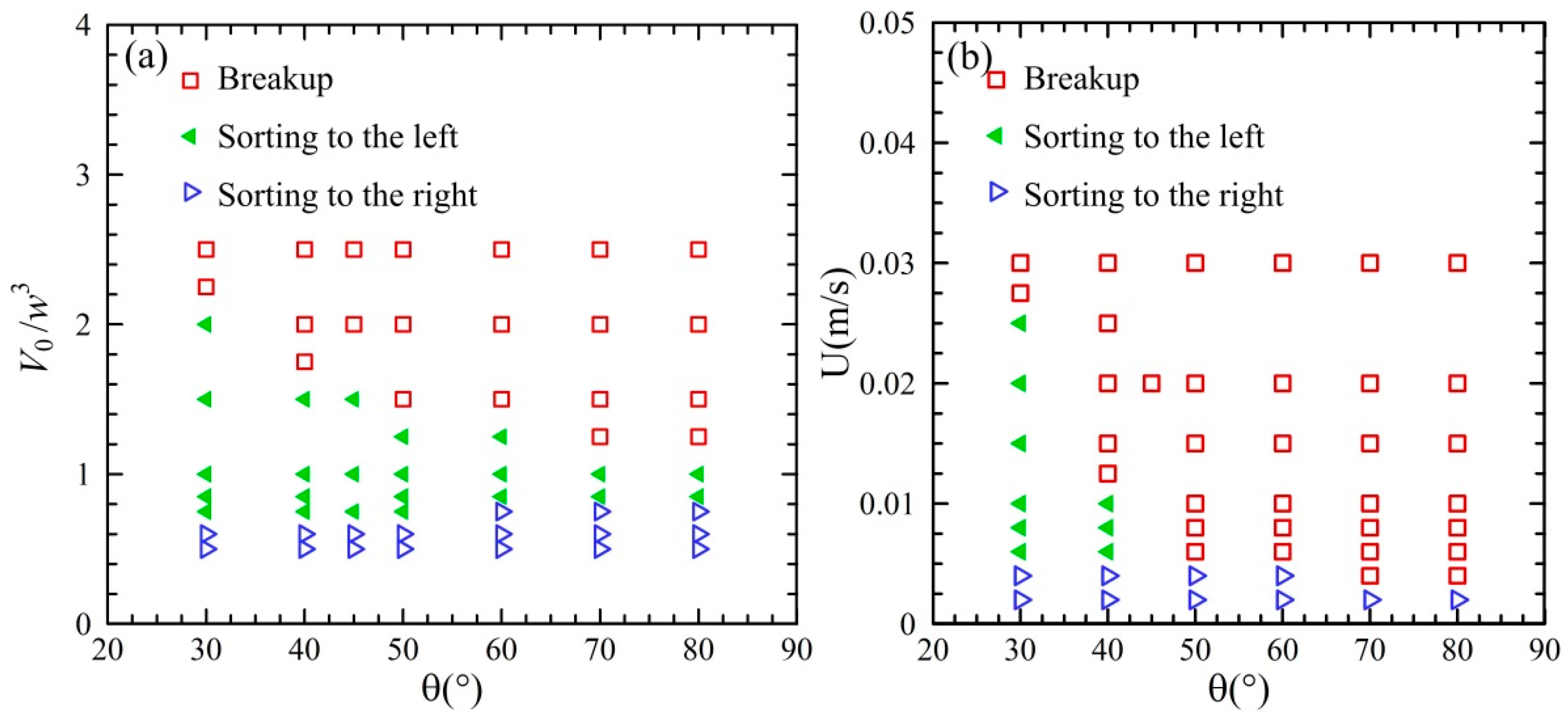
3.3. Phase Regime of Droplet Behavior in the Acute Junction

The phase regime of the droplet sorting in the acute junction was examined, as shown in Figure 12. The angle θ of the acute junction varied from 30° to 80°. The non-dimensional volume of the droplet was within in the range of Vd/w3 = 0.5 ~ 2.5 and the velocity was from 4 mm/s to 20 mm/s. The dependence of the phase regime on the droplet volume and the junction angle is shown in Figure 12a. The velocity was fixed at U = 20 mm/s. For the droplet volume over Vd/w3 = 1.0 ~ 2.5, the droplet undergoes a transition from breakup to sorting left, with the decrease in droplet volume. For the droplet volume over Vd/w3 = 0.5 ~ 1.0, a transition from sorting left to sorting right can be observed with the reduction in droplet volume. The junction angle has a significant effect on the transition between breakup and sorting left, but not between sorting left and sorting right. The dependence of the droplet behavior on the velocity and the junction angle is presented in Figure 12b. The non-dimensional volume of the droplet is of Vd/w3 = 2. For the junction angle θ = 30° and 40°, the droplet exhibits a transition from breakup to sorting left and then to sorting right, with the reduction in the velocity. For the junction angle θ = 50° ~ 80°, the transition from breakup to sorting right can be observed with the decrease in the velocity. Therefore, droplet breakup occurs at large volume or high velocity, while droplet sorting is present at relatively small volume and low velocity. A careful consideration should be made to fulfil the droplet sorting with asymmetric acute junctions.
Figure 12. Phase regime of droplet sorting in the asymmetric acute junctions: (a) U = 20 mm/s and (b) Vd/w3 = 2.
Micromachines 13 01640 g012

4. Discussion

In most real droplet-based microfluidics, the fluorinated oil FC40 is one of commonly used medium fluid and 1–5% PEG-PFPE is used as surfactant. To examine whether the proposed method can be used in real experiments, we further investigated the volume-based droplet sorting in the acute junction with an angle of θ = 50°. In these simulations, FC40 was used as the medium fluid, with the density and viscosity of ρm = 1850 kg/m3 and μm = 4.1×10⁻³ Pa·s, respectively. Following the experimental studies of droplet flow in Refs. [74,75], in which 1–5% PEG-PFPF was used for the surfactant, three values of interfacial tensions were chosen, i.e., σ = 3, 7, and 12 mN/m. The channel walls were set to be hydrophobic with a contact angle of 150°. Figure 13 presents the droplet sorting behavior at different interfacial tensions. It is observed that the droplet exhibits different sorting behavior at different interfacial tensions. The droplet with the volume of Vd/w3 = 0.85 enters into the left channel at the interfacial tension of σ = 3 mN/m while moving into the right channel at σ = 7 and 12 mN/m. Moreover, the droplet undergoes a transition of sorting left to sorting right with the reduction in Vd/w3 from 0.85 to 0.6 at σ = 3 mN/m. In contrast, the droplets with the volume of Vd/w3 = 0.85 and 0.6 are all sorted to the right channel at σ = 7 and 12 mN/m. These facts indicate that the interfacial tension has a great impact on the sorting behavior. It can be inferred that the boundary between sorting left and sorting right in the phase regime is different at various interfacial tension. In spite of this, these results show that the proposed asymmetric acute junction could be used for droplet sorting in real applications of droplet-based microfluidics.
Many methods have been developed for droplet sorting in recent years. For example, acoustic methods can achieve the on-demand sorting of the droplets [31,32]. However, one disadvantage of acoustic methods is that their operation requires expensive and complex equipment, such as function generators, voltage amplifiers, signal processors, and acoustic transducers [36]. In contrast, the proposed passive sorting method only relies on the geometry of asymmetric acute junctions. It has the advantages of simple-fabrication and cost-effective. Additionally, a high-throughput sorting could be achieved using a combination of a massive number of acute junctions in one microfluidic chip.

5. Conclusions

This work presented numerical investigations on the droplet sorting in the asymmetric junctions. We found that the asymmetric acute junction could be used for passive droplet sorting. Both volume-based and velocity-based droplet sortings can be achieved in the asymmetric acute junctions. For volume-based droplet sorting, large droplets are sorted to the left channel, while small droplets are sorted to the right channel. For velocity-based droplet sorting, fast droplets are sorted to the left channel, while slow droplets are sorted to the right channel. The physical mechanism behind the droplet sorting is associated with the pressure distribution surrounding the droplet when the droplet enters into the junction. The droplet can be sorted to the left if the accumulated pressure at the rear of the droplet could open a tunnel between the droplet and the obtuse corner of the asymmetric junction. A phase diagram of the droplet sorting is presented to unveil the dependence of the droplet sorting on the droplet volume and the velocity at various junction angles. Further work is required to experimentally investigate passive droplet sorting using asymmetric acute junction and systematic studies on the effect of the junction geometry on the sorting accuracy of the droplets with different sizes and deformability. Moreover, this sorting method based on the acute junction could be integrated with other sorting methods to further improve the sorting performance.

Author Contributions

Conceptualization, H.Y. and T.P.J.K.; methodology, H.Y.; numerical simulation, H.Y.; validation, H.Y.; formal analysis, H.Y. and T.P.J.K.; investigation, H.Y.; writing—original draft preparation, H.Y.; writing—review and editing, H.Y. and T.P.J.K.; supervision, T.P.J.K.; funding acquisition, H.Y. All authors regularly discussed the progress during the entire work. All authors have read and agreed to the published version of the manuscript.

Funding

This research was funded by Postdoctoral Fellowship of China Scholarship Council (CSC) under grant No.201908330071.

Conflicts of Interest

The authors declare no conflict of interest.

References

  1. Teh, S.Y.; Lin, R.; Hung, L.H.; Lee, A.P. Droplet microfluidics. Lab Chip 2008, 8, 198–220. [Google Scholar] [CrossRef]
  2. Taniguchi, T.; Torii, T.; Higuchi, T. Chemical reactions in microdroplets by electrostatic manipulation of droplets in liquid media. Lab Chip 2002, 2, 19–23. [Google Scholar] [CrossRef]
  3. Wu, J.; Yadavali, S.; Lee, D.; Issadore, D.A. Scaling up the throughput of microfluidic droplet-based materials synthesis: A review of recent progress and outlook. Appl. Phys. Rev. 2021, 8, 031304. [Google Scholar] [CrossRef] [PubMed]
  4. Bawazer, L.A.; McNally, C.S.; Empson, C.J.; Marchant, W.J.; Comyn, T.P.; Niu, X.; Cho, S.; Mcpherson, M.J.; Binks, B.P.; Demello, A.; et al. Combinatorial microfluidic droplet engineering for biomimetic material synthesis. Sci. Adv. 2016, 2, e1600567. [Google Scholar] [CrossRef]
  5. Gielen, F.; Hours, R.; Emond, S.; Fischlechner, M.; Schell, U.; Hollfelder, F. Ultrahigh-throughput–directed enzyme evolution by absorbance-activated droplet sorting (AADS). Proc. Natl. Acad. Sci. USA 2016, 113, E7383–E7389. [Google Scholar] [CrossRef]
  6. Qamar, S.; Wang, G.Z.; Randle, S.J.; Ruggeri, F.S.; Varela, J.A.; Lin, J.Q.; Phillips, E.C.; Miyashita, A.; Williams, D.; Strohl, F.; et al. FUS phase separation is modulated by a molecular chaperone and methylation of arginine cation-π interactions. Cell 2018, 173, 720–734.e15. [Google Scholar] [CrossRef]
  7. Toprakcioglu, Z.; Challa, P.K.; Morse, D.B.; Knowles, T. Attoliter protein nanogels from droplet nanofluidics for intracellular delivery. Sci. Adv. 2020, 6, eaay7952. [Google Scholar] [CrossRef]
  8. Fallah-Araghi, A.; Baret, J.C.; Ryckelynck, M.; Griffiths, A.D. A completely in vitro ultrahigh-throughput droplet-based microfluidic screening system for protein engineering and directed evolution. Lab Chip 2012, 12, 882–891. [Google Scholar] [CrossRef]
  9. Dittrich, P.S.; Manz, A. Lab-on-a-chip: Microfluidics in drug discovery. Nat. Rev. Drug Discov. 2006, 5, 210–218. [Google Scholar] [CrossRef]
  10. Neužil, P.; Giselbrecht, S.; Länge, K.; Huang, T.J.; Manz, A. Revisiting lab-on-a-chip technology for drug discovery. Nat. Rev. Drug Discov. 2012, 11, 620–632. [Google Scholar] [CrossRef]
  11. Schneider, G. Automating drug discovery. Nat. Rev. Drug Discov. 2018, 17, 97–113. [Google Scholar] [CrossRef]
  12. Mazutis, L.; Gilbert, J.; Ung, W.L.; Weitz, D.A.; Griffiths, A.D.; Heyman, J.A. Single-cell analysis and sorting using droplet-based microfluidics. Nat. Protoc. 2013, 8, 870–891. [Google Scholar] [CrossRef]
  13. Nieuwelink, A.E.; Vollenbroek, J.C.; Tiggelaar, R.M.; Bomer, J.G.; van den Berg, A.; Odijk, M.; Weckhuysen, B.M. High-throughput activity screening and sorting of single catalyst particles with a droplet microreactor using dielectrophoresis. Nat. Catal. 2021, 4, 1070–1079. [Google Scholar] [CrossRef]
  14. Niu, X.; Gielen, F.; Edel, J.B.; Demello, A.J. A microdroplet dilutor for high-throughput screening. Nat. Chem. 2011, 3, 437–442. [Google Scholar] [CrossRef] [PubMed]
  15. Miller, O.J.; Harrak, A.E.; Mangeat, T.; Baret, J.C.; Frenz, L.; Debs, B.E.; Mayot, E.; Samuels, M.L.; Rooney, E.K.; Dieu, P.; et al. High-resolution dose–response screening using droplet-based microfluidics. Proc. Natl. Acad. Sci. USA 2012, 109, 378–383. [Google Scholar] [CrossRef]
  16. Mutafopulos, K.; Lu, P.J.; Garry, R.; Spink, P.; Weitz, D.A. Selective cell encapsulation, lysis, pico-injection and size-controlled droplet generation using traveling surface acoustic waves in a microfluidic device. Lab Chip 2020, 20, 3914–3921. [Google Scholar] [CrossRef]
  17. Xi, H.D.; Zheng, H.; Guo, W.; Gañán-Calvo, A.M.; Ai, Y.; Tsao, C.W.; Zhou, J.; Li, W.; Huang, Y.; Nguyen, N.-T.; et al. Active droplet sorting in microfluidics: A review. Lab Chip 2017, 17, 751–771. [Google Scholar] [CrossRef] [PubMed]
  18. Shen, Y.; Yalikun, Y.; Tanaka, Y. Recent advances in microfluidic cell sorting systems. Sens. Actuat. B-Chem. 2019, 282, 268–281. [Google Scholar] [CrossRef]
  19. Link, D.R.; Grasland-Mongrain, E.; Duri, A.; Sarrazin, F.; Cheng, Z.; Cristobal, G.; Marquez, M.; Weitz, D.A. Electric control of droplets in microfluidic devices. Angew. Chem. Int. Edit. 2006, 45, 2556–2560. [Google Scholar] [CrossRef] [PubMed]
  20. Niu, X.; Zhang, M.; Peng, S.; Wen, W.; Sheng, P. Real-time detection, control, and sorting of microfluidic droplets. Biomicrofluidics 2007, 1, 044101. [Google Scholar] [CrossRef] [Green Version]
  21. Ahn, B.; Lee, K.; Louge, R.; Oh, K.W. Concurrent droplet charging and sorting by electrostatic actuation. Biomicrofluidics 2009, 3, 044102. [Google Scholar] [CrossRef] [PubMed]
  22. Ahn, B.; Lee, K.; Panchapakesan, R.; Oh, K.W. On-demand electrostatic droplet charging and sorting. Biomicrofluidics 2011, 5, 024113. [Google Scholar] [CrossRef] [PubMed]
  23. Rao, L.; Cai, B.; Wang, J.; Meng, Q.; Ma, C.; He, Z.; Xu, J.; Huang, Q.; Li, S.; Cen, Y.; et al. A microfluidic electrostatic separator based on pre-charged droplets. Sensor. Actuat. B-Chem. 2015, 210, 328–335. [Google Scholar] [CrossRef]
  24. Ahn, K.; Kerbage, C.; Hunt, T.P.; Westervelt, R.M.; Link, D.R.; Weitz, D.A. Dielectrophoretic manipulation of drops for high-speed microfluidic sorting devices. Appl. Phys. Lett. 2006, 88, 024104. [Google Scholar] [CrossRef]
  25. Schütz, S.S.; Beneyton, T.; Baret, J.C.; Schneider, T.M. Rational design of a high-throughput droplet sorter. Lab Chip 2019, 19, 2220–2232. [Google Scholar] [CrossRef] [PubMed]
  26. Frenzel, D.; Merten, C.A. Microfluidic train station: Highly robust and multiplexable sorting of droplets on electric rails. Lab Chip 2017, 17, 1024–1030. [Google Scholar] [CrossRef]
  27. Teo, A.J.; Tan, S.H.; Nguyen, N.T. On-demand droplet merging with an AC electric field for multiple-volume droplet generation. Anal. Chem. 2019, 92, 1147–1153. [Google Scholar] [CrossRef]
  28. Sesen, M.; Alan, T.; Neild, A. Microfluidic plug steering using surface acoustic waves. Lab Chip 2015, 15, 3030–3038. [Google Scholar] [CrossRef]
  29. Franke, T.; Abate, A.R.; Weitz, D.A.; Wixforth, A. Surface acoustic wave (SAW) directed droplet flow in microfluidics for PDMS devices. Lab Chip 2009, 9, 2625–2627. [Google Scholar] [CrossRef]
  30. Nam, H.; Sung, H.J.; Park, J.; Jeon, J.S. Manipulation of cancer cells in a sessile droplet via travelling surface acoustic waves. Lab Chip 2022, 22, 47–56. [Google Scholar] [CrossRef]
  31. Zhong, R.; Yang, S.; Ugolini, G.S.; Naquin, T.; Zhang, J.; Yang, K.; Xia, J.; Konry, T.; Huang, T.J. Acoustofluidic Droplet Sorter Based on Single Phase Focused Transducers. Small 2021, 17, 2103848. [Google Scholar] [CrossRef] [PubMed]
  32. Li, S.; Ding, X.; Guo, F.; Chen, Y.; Lapsley, M.I.; Lin, S.C.S.; Huang, T.J. An on-chip, multichannel droplet sorter using standing surface acoustic waves. Anal. Chem. 2013, 85, 5468–5474. [Google Scholar] [CrossRef] [PubMed]
  33. Ding, X.; Lin, S.C.S.; Kiraly, B.; Yue, H.; Li, S.; Chiang, I.K.; Shi, J.; Benkovic, S.J.; Huang, T.J. On-chip manipulation of single microparticles, cells, and organisms using surface acoustic waves. Proc. Natl. Acad. Sci. USA 2012, 109, 11105–11109. [Google Scholar] [CrossRef]
  34. Yeo, L.Y.; Friend, J.R. Surface acoustic wave microfluidics. Annu. Rev. Fluid Mech. 2014, 46, 379–406. [Google Scholar] [CrossRef]
  35. Leibacher, I.; Reichert, P.; Dual, J. Microfluidic droplet handling by bulk acoustic wave (BAW) acoustophoresis. Lab Chip 2015, 15, 2896–2905. [Google Scholar] [CrossRef] [PubMed]
  36. Zhang, P.; Bachman, H.; Ozcelik, A.; Huang, T.J. Acoustic microfluidics. Annu. Rev. Anal. Chem. 2020, 13, 17. [Google Scholar] [CrossRef]
  37. Nguyen, N.T.; Zhu, G.; Chua, Y.C.; Phan, V.N.; Tan, S.H. Magnetowetting and sliding motion of a sessile ferrofluid droplet in the presence of a permanent magnet. Langmuir 2010, 26, 12553–12559. [Google Scholar] [CrossRef]
  38. Zhang, K.; Liang, Q.; Ma, S.; Mu, X.; Hu, P.; Wang, Y.; Luo, G. On-chip manipulation of continuous picoliter-volume superparamagnetic droplets using a magnetic force. Lab Chip 2009, 9, 2992–2999. [Google Scholar] [CrossRef]
  39. Demirörs, A.F.; Aykut, S.; Ganzeboom, S.; Meier, Y.A.; Poloni, E. Programmable droplet manipulation and wetting with soft magnetic carpets. Proc. Natl. Acad. Sci. USA 2021, 118, e2111291118. [Google Scholar] [CrossRef]
  40. Chen, A.; Byvank, T.; Chang, W.J.; Bharde, A.; Vieira, G.; Miller, B.L.; Chalmers, J.J.; Bashir, R.; Sooryakumar, R. On-chip magnetic separation and encapsulation of cells in droplets. Lab Chip 2013, 13, 1172–1181. [Google Scholar] [CrossRef] [Green Version]
  41. Chen, Y.; Tian, Y.; Xu, Z.; Wang, X.; Yu, S.; Dong, L. Microfluidic droplet sorting using integrated bilayer micro-valves. Appl. Phys. Lett. 2016, 109, 143510. [Google Scholar] [CrossRef]
  42. Cao, Z.; Chen, F.; Bao, N.; He, H.; Xu, P.; Jana, S.; Jung, S.; Lian, H.; Lu, C. Droplet sorting based on the number of encapsulated particles using a solenoid valve. Lab Chip 2013, 13, 171–178. [Google Scholar] [CrossRef] [PubMed]
  43. Miralles, V.; Huerre, A.; Williams, H.; Fournié, B.; Jullien, M.C. A versatile technology for droplet-based microfluidics: Thermomechanical actuation. Lab Chip 2015, 15, 2133–2139. [Google Scholar] [CrossRef] [PubMed]
  44. Fradet, E.; McDougall, C.; Abbyad, P.; Dangla, R.; Mcgloin, D.; Baroud, C.N. Combining rails and anchors with laser forcing for selective manipulation within 2D droplet arrays. Lab Chip 2011, 11, 4228–4234. [Google Scholar] [CrossRef] [PubMed]
  45. Luo, X.; Luo, Z.Y.; Bai, B.F. Effect of thermal convection on thermocapillary migration of a surfactant-laden droplet in a microchannel. Phys. Fluids 2020, 32, 092009. [Google Scholar] [CrossRef]
  46. Gossett, D.R.; Weaver, W.M.; Mach, A.J.; Hur, S.C.; Tse, H.T.K.; Lee, W.; Amini, H.; Di Carlo, D. Label-free cell separation and sorting in microfluidic systems. Anal. Bioanal. Chem. 2010, 397, 3249–3267. [Google Scholar] [CrossRef]
  47. HyunáYoon, D. Hydrodynamic on-rail droplet pass filter for fully passive sorting of droplet-phase samples. RSC Adv. 2014, 4, 37721–37725. [Google Scholar] [CrossRef]
  48. Rashid, Z.; Erten, A.; Morova, B.; Muradoglu, M.; Jonáš, A.; Kiraz, A. Passive sorting of emulsion droplets with different interfacial properties using laser-patterned surfaces. Microfluid. Nanofluidics 2019, 23, 65. [Google Scholar] [CrossRef]
  49. Li, M.; van Zee, M.; Goda, K.; Di Carlo, D. Size-based sorting of hydrogel droplets using inertial microfluidics. Lab Chip 2018, 18, 2575–2582. [Google Scholar] [CrossRef]
  50. Joensson, H.N.; Uhlén, M.; Svahn, H.A. Droplet size based separation by deterministic lateral displacement-separating droplets by cell-induced shrinking. Lab Chip 2011, 11, 1305–1310. [Google Scholar] [CrossRef]
  51. Ding, R.; Ung, W.L.; Heyman, J.A.; Weitz, D.A. Sensitive and predictable separation of microfluidic droplets by size using in-line passive filter. Biomicrofluidics 2017, 11, 014114. [Google Scholar] [CrossRef] [PubMed]
  52. Yoon, D.H.; Xie, Z.; Tanaka, D.; Sekiguchi, T.; Shoji, S. A high-resolution passive droplet-phase sample sorter using multi-stage droplet transfer. RSC Adv. 2017, 7, 36750–36754. [Google Scholar] [CrossRef]
  53. Di Carlo, D.; Irimia, D.; Tompkins, R.G.; Toner, M. Continuous inertial focusing, ordering, and separation of particles in microchannels. Proc. Natl. Acad. Sci. USA 2007, 104, 18892–18897. [Google Scholar] [CrossRef]
  54. Hur, S.C.; Henderson-MacLennan, N.K.; McCabe, E.R.; Di Carlo, D. Deformability-based cell classification and enrichment using inertial microfluidics. Lab Chip 2011, 11, 912–920. [Google Scholar] [CrossRef] [PubMed]
  55. Kabacaoğlu, G.; Biros, G. Sorting same-size red blood cells in deep deterministic lateral displacement devices. J. Fluid Mech. 2019, 859, 433–475. [Google Scholar] [CrossRef]
  56. Xavier, M.; Holm, S.H.; Beech, J.P.; Spencer, D.; Tegenfeldt, J.O.; Oreffo, R.O.; Morgan, H. Label-free enrichment of primary human skeletal progenitor cells using deterministic lateral displacement. Lab Chip 2019, 19, 513–523. [Google Scholar] [CrossRef] [PubMed]
  57. Hochstetter, A.; Vernekar, R.; Austin, R.H.; Becker, H.; Beech, J.P.; Fedosov, D.A.; Gompper, G.; Kim, S.-C.; Smith, J.T.; Stolovitzky, G.; et al. Deterministic lateral displacement: Challenges and perspectives. ACS Nano 2020, 14, 10784–10795. [Google Scholar] [CrossRef] [PubMed]
  58. McGrath, J.; Jimenez, M.; Bridle, H. Deterministic lateral displacement for particle separation: A review. Lab Chip 2014, 14, 4139–4158. [Google Scholar] [CrossRef] [PubMed]
  59. Fu, Y.; Bai, L.; Jin, Y.; Cheng, Y. Theoretical analysis and simulation of obstructed breakup of micro-droplet in T-junction under an asymmetric pressure difference. Phys. Fluids 2017, 29, 032003. [Google Scholar] [CrossRef]
  60. Bedram, A.; Moosavi, A.; Hannani, S.K. Analytical relations for long-droplet breakup in asymmetric T junctions. Phys. Rev. E 2015, 91, 053012. [Google Scholar] [CrossRef] [Green Version]
  61. Samie, M.; Salari, A.; Shafii, M.B. Breakup of microdroplets in asymmetric T junctions. Phys. Rev. E 2013, 87, 053003. [Google Scholar] [CrossRef]
  62. Raad, M.; Rezazadeh, S.; Jalili, H.; Abbasinezhad Fallah, D. A numerical study of droplet splitting in branched T-shaped microchannel using the two-phase level-set method. Adv. Mech. Eng. 2021, 13, 16878140211045487. [Google Scholar] [CrossRef]
  63. Ménétrier-Deremble, L.; Tabeling, P. Droplet breakup in microfluidic junctions of arbitrary angles. Phys. Rev. E 2006, 74, 035303. [Google Scholar] [CrossRef]
  64. Wang, X.; Liu, Z.; Pang, Y. Droplet breakup in an asymmetric bifurcation with two angled branches. Chem. Eng. Sci. 2018, 188, 11–17. [Google Scholar] [CrossRef]
  65. Hoang, D.A.; Portela, L.M.; Kleijn, C.R.; Kreutzer, M.T.; Van Steijn, V. Dynamics of droplet breakup in a T-junction. J. Fluid Mech. 2013, 717, R4. [Google Scholar] [CrossRef]
  66. Hirt, C.W.; Nichols, B.D. Volume of fluid (VOF) method for the dynamics of free boundaries. J. Comput. Phys. 1981, 39, 201–225. [Google Scholar] [CrossRef]
  67. Zheng, M.; Ma, Y.; Jin, T.; Wang, J. Effects of topological changes in microchannel geometries on the asymmetric breakup of a droplet. Microfluid. Nanofluidics 2016, 20, 1–22. [Google Scholar] [CrossRef]
  68. Sivasamy, J.; Wong, T.N.; Nguyen, N.T.; Kao, L.T.H. An investigation on the mechanism of droplet formation in a microfluidic T-junction. Microfluid. Nanofluidics 2011, 11, 1–10. [Google Scholar] [CrossRef]
  69. Agnihotri, S.N.; Raveshi, M.R.; Bhardwaj, R.; Neild, A. Droplet breakup at the entrance to a bypass channel in a microfluidic system. Phys. Rev. Appl. 2019, 11, 034020. [Google Scholar] [CrossRef]
  70. Brackbill, J.U.; Kothe, D.B.; Zemach, C. A continuum method for modeling surface tension. J. Comput. Phys. 1992, 100, 335–354. [Google Scholar] [CrossRef]
  71. Kobayashi, I.; Vladisavljević, G.T.; Uemura, K.; Nakajima, M. CFD analysis of microchannel emulsification: Droplet generation process and size effect of asymmetric straight flow-through microchannels. Chem. Eng. Sci. 2011, 66, 5556–5565. [Google Scholar] [CrossRef]
  72. Chen, Y.; Deng, Z. Hydrodynamics of a droplet passing through a microfluidic T-junction. J. Fluid Mech. 2017, 819, 401–434. [Google Scholar] [CrossRef]
  73. Xi, H.; Duncan, C. Lattice Boltzmann simulations of three-dimensional single droplet deformation and breakup under simple shear flow. Phys. Rev. E 1999, 59, 3022. [Google Scholar] [CrossRef]
  74. Dangla, R.; Kayi, S.C.; Baroud, C.N. Droplet microfluidics driven by gradients of confinement. Proc. Natl. Acad. Sci. USA 2013, 110, 853–858. [Google Scholar] [CrossRef]
  75. Mazutis, L.; Griffiths, A.D. Selective droplet coalescence using microfluidic systems. Lab Chip 2012, 12, 1800–1806. [Google Scholar] [CrossRef] [PubMed]
Figure 1. Geometry of the asymmetric acute junction.
Micromachines 13 01640 g001
Figure 2. Numerical validation of Laplace’s law.
Micromachines 13 01640 g002
Figure 3. Droplet deformation in a simple shear flow.
Micromachines 13 01640 g003
Figure 4. Passive sorting of large droplet into the left channel (θ = 50°, U = 20 mm/s, Vd/w3 = 0.85). (a) T0, (b) T1 = T0 + 0.8, (c) T2 = T0 + 1.4, (d) T3 = T0 + 1.8, (e) T4 = T0 + 2.8, (f) T5 = T0 + 4.8.
Micromachines 13 01640 g004
Figure 5. Pressure distributions along the centreline of the branching channels at a droplet volume of Vd/w3 = 0.85 (θ = 50°, U = 20 mm/s). (a) T0, (b) T1, (c) T2, (d) T3, (e) T4, (f) T5.
Micromachines 13 01640 g005
Figure 6. Passive sorting of small droplet into the right channel (θ = 50°, U = 20 mm/s, Vd/w3 = 0.6). (a) T0, (b) T1 = T0 + 0.6, (c) T2 = T0 + 1, (d) T3 = T0 + 1.6, (e) T4 = T0 + 2.8, (f) T5 = T0 + 3.6.
Micromachines 13 01640 g006
Figure 7. Pressure distributions along the centreline of the branching channels when the droplet is sorted into the right channel at Vd/w3 = 0.6 (θ = 50°, U = 20 mm/s). (a) T0, (b) T1, (c) T2, (d) T3, (e) T4, (f) T5.
Micromachines 13 01640 g007
Figure 8. Passive sorting of droplet into the left channel at a relatively large velocity of U = 10 mm/s (θ = 40°, Vd/w3 = 2). (a) T0, (b) T1 = T0 + 2.55, (c) T2 = T0 + 3.25, (d) T3 = T0 + 3.75, (e) T4 = T0 + 4.65, (f) T5 = T0 + 6.05.
Micromachines 13 01640 g008
Figure 9. Pressure distributions along the centreline of the branching channels when the droplet is sorted into the left channel at U = 10 mm/s (θ = 40°, Vd/w3 = 2). (a) T0, (b) T1, (c) T2, (d) T3, (e) T4, (f) T5.
Micromachines 13 01640 g009
Figure 10. Passive sorting of droplet into the right channel at the relatively small velocity of U = 4 mm/s (θ = 40°, Vd/w3 = 2). (a) T0, (b) T1 = T0 + 2.56, (c) T2 = T0 + 3.52, (d) T3 = T0 + 4, (e) T4 = T0 + 4.48, (f) T5 = T0 + 8.
Micromachines 13 01640 g010
Figure 11. Pressure distributions along the centreline of the branching channels when the droplet is sorted into the right channel at U = 4 mm/s (θ = 40°, Vd/w3 = 2). (a) T0, (b) T1, (c) T2, (d) T3, (e) T4, (f) T5.
Micromachines 13 01640 g011
Figure 13. Droplet sorting in the asymmetric acute junction with the angle of θ = 50° at various interfacial tensions. (a) Vd/w3 = 0.85, σ = 3 mN/m, (b) Vd/w3 = 0.85, σ = 7 mN/m, (c) Vd/w3 = 0.85, σ = 12 mN/m, (d) Vd/w3 = 0.6, σ = 3 mN/m, (e) Vd/w3 = 0.6, σ = 7 mN/m 4, (f) Vd/w3 = 0.6, σ = 12 mN/m.
Micromachines 13 01640 g013
Publisher’s Note: MDPI stays neutral with regard to jurisdictional claims in published maps and institutional affiliations.

