Article

A Shear-Mode Magnetoelectric Heterostructure with Enhanced Magnetoelectric Response for Stray Power-Frequency Magnetic Field Energy Harvesting

School of Information Engineering, Baise University, Baise 533000, China
Micromachines 2022, 13(11), 1882; https://doi.org/10.3390/mi13111882
Submission received: 29 September 2022 / Revised: 29 October 2022 / Accepted: 31 October 2022 / Published: 1 November 2022
(This article belongs to the Special Issue Recent Advances in Magnetoelectric Materials and Devices)

Abstract

:
This paper devises a magnetoelectric (ME) heterostructure to harvest ambient stray power-frequency (50 Hz or 60 Hz) magnetic field energy. The device explores the shear piezoelectric effect of the PZT-5A plates and the magnetostrictive activity of the Terfenol-D plates. The utilization of the high-permeability films helps to enhance the magnetoelectric response to the applied alternating magnetic field. A theoretical model is developed based on the piezomagnetic and piezoelectric constitutive equations as well as the boundary conditions. The ME response of the device is characterized theoretically and experimentally. The measured ME voltage coefficient attains 165.2 mV/Oe at the frequency of 50 Hz, which shows a good agreement with the theoretical result. The feasibility for extracting energy from the 50 Hz magnetic field is validated. Under an external alternating magnetic field of 30 Oe, a maximum power of 8.69 μW is generated across an optimal load resistance of 693 kΩ. Improvements of the ME heterostructure are practicable, which allows an enhancement of the ME voltage coefficient and the maximum power by optimizing the structural parameters and utilizing PMN-PT with a higher shear-mode piezoelectric voltage coefficient (g15).

1. Introduction

With the development of the wireless sensor networks (WSNs), higher demands on the power supply of the sensor nodes have been put forward. The traditional batteries cannot satisfy the requirement on the long-term operation of the sensor nodes due to the limited energy. A prospective method to address this issue is using energy harvesting technology, which extracts energy from ambient energy sources. Researchers have conducted investigations on different energy sources, such as sunlight [1], sound [2,3], heat [4,5], human motion [6,7,8], and mechanical vibration [9,10,11], and a variety of schemes for different energy sources have been developed [12,13,14].
The stray power-frequency (50 Hz or 60 Hz) magnetic field originating from electric power systems (e.g., power lines, busbars) is another promising energy source for energy harvesting. The feasibility for harvesting energy from a 50 Hz or 60 Hz magnetic field has been explored. A typical scheme is utilizing a current transformer [15], but the intrinsic shortcomings (e.g., saturation, sharp outputs) render the device unpractical. Mechanisms based on piezoelectric cantilever beams have been presented to extract energy from the power-frequency magnetic field [16,17]. To achieve maximum outputs, the devices need to be tuned to the targeted frequency of 50 Hz or 60 Hz.
Magnetoelectric (ME) laminate composites have been proved to be effective in magnetoelectric transduction [18,19]. Cantilever-based resonant structures using ME laminate composites have been devised to harvest 50 Hz magnetic field energy from power lines [20,21], and the resonant frequency also needs to be adjusted due to the nonlinear magnetic force. In real applications, a non-resonant energy harvesting device might be preferred for a 50 Hz or 60 Hz magnetic field. The conventional ME laminate composites (e.g., MP and MPM structures) can be used as non-resonant devices to extract such low-frequency (50 Hz or 60 Hz) magnetic field energy, but it is estimated that the harvested energy is quite low. ME structures have been devised to enhance the ME responses [22,23,24,25], including improving the piezomagnetic coefficient [22], exploring the shear piezoelectric effect [23,24], and using a mechanically mediated device [25], but the ME responses at the power frequency (50 Hz or 60 Hz) are not investigated in the above literature.
In this paper, a ME heterostructure with an enhanced ME response is presented. Shear piezoelectric effect is induced due to the shrinkage/elongation activity of the Terfenol-D plates and the maintaining of retaining plates. Theoretical analysis has been performed to predict the ME voltage coefficient and the maximum power, and the theoretical results match the experimental results well. The feasibility for harvesting the 50 Hz magnetic field is verified, and the output power can be further improved by structure and material optimization.

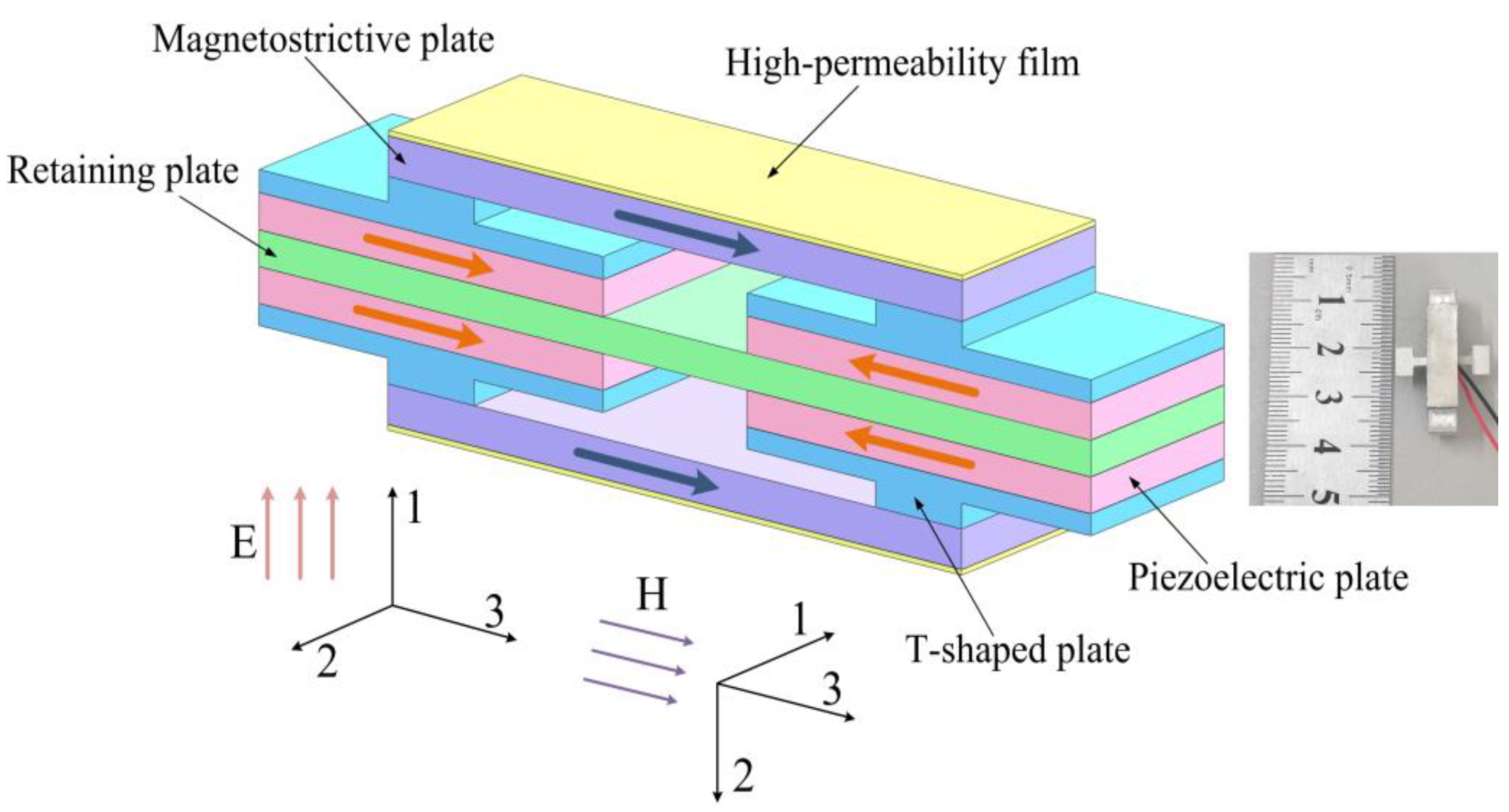
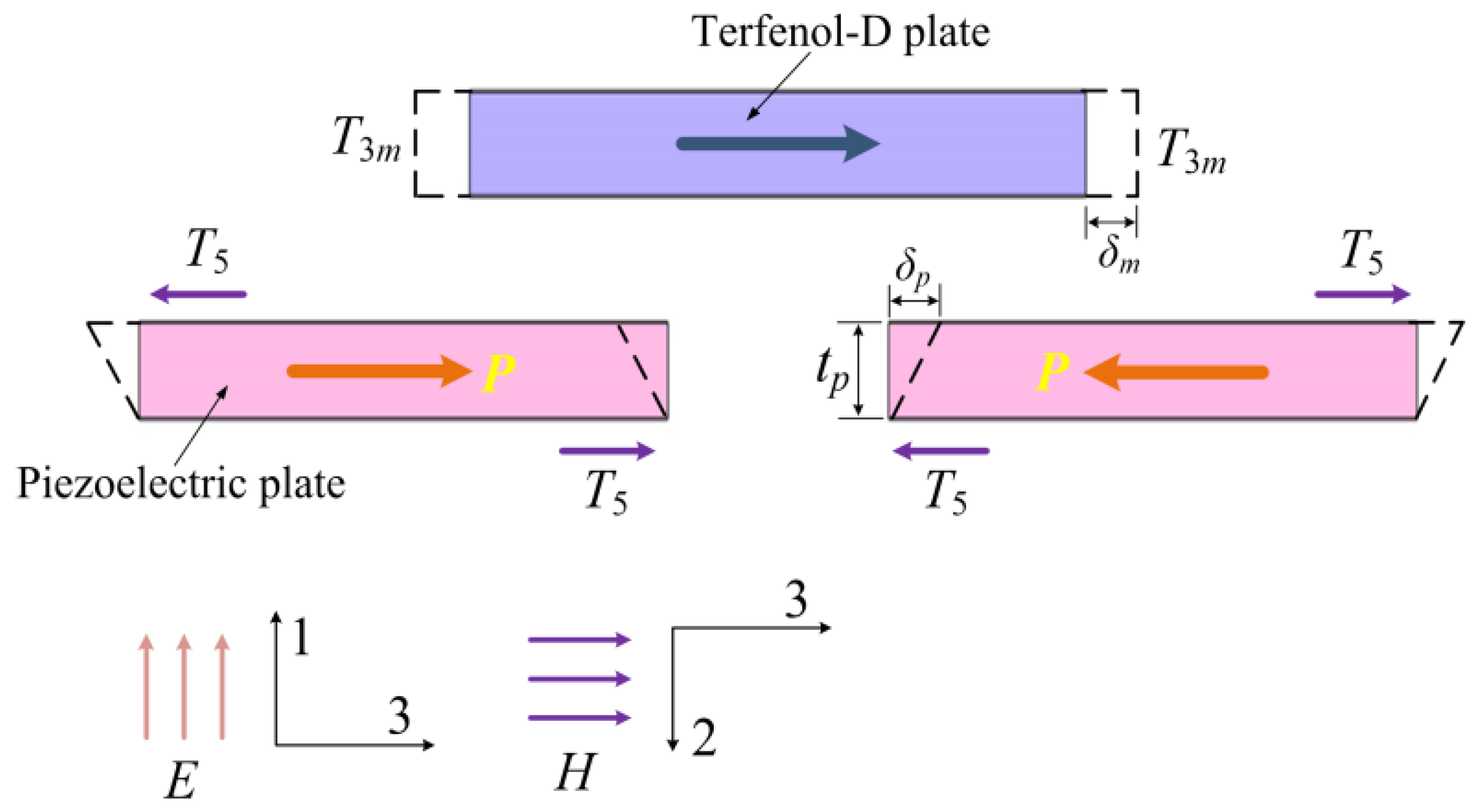
2. Magnetoelectric Heterostructure

Figure 1 shows the schematic diagram of the proposed shear-mode ME heterostructure. Two coordinate systems are used for the piezoelectric plates and the magnetostrictive plates, which respectively apply to the piezoelectric and piezomagnetic constitutive equations. The device consists of four shear-mode piezoelectric plates (PZT-5A), four T-shaped retaining plates, two magnetostrictive plates (Terfenol-D), a rectangular retaining plate, and two high-permeability films bonded on the surfaces of the Terfenol-D plates. A longitudinal shift of the Terfenol-D plate is induced when an alternating magnetic field (along the 3-direction) is applied due to the magnetostrictive effect. The stress of the Terfenol-D plate is transmitted to the PZT-5A plate by the T-shaped retaining plate. Shear stress is then produced on the PZT-5A plate as a result of the effect of the T-shaped and rectangular retaining plates. The PZT-5A plate produces a voltage output owing to the shear piezoelectric effect, as shown in Figure 2. The employing of the high-permeability films helps to enhance the piezomagnetic coefficient as well as the ME voltage coefficient, which can potentially improve the output power for an ambient low-frequency magnetic field (e.g., stray 50 Hz power-frequency magnetic field) energy harvesting.
After bonding a high-permeability film on the surface of the Terfenol-D plate, the internal effective magnetic field of the magnetostrictive plate can be expressed as
H e f f H d c + H f 1 + χ N d ,
where Hdc is the applied bias magnetic field, Hf is the additional magnetic field produced by the film, which can be calculated using equivalent magnetic charge method [26], χ is the magnetization coefficient, and Nd is the demagnetizing factor. The effective piezomagnetic coefficient is given by [27,28]
d 33 , m e f f = 2 λ s ( μ r 1 ) 2 H e f f M s 2 { 1 tanh ( T T s ) ( T 0 ) 1 tanh ( 2 T / T s )   2 ( T < 0 ) ,
T = E f E m t f Δ ε 1 ( 1 ν ) ( E f t f + E m t m ) ,
where λs is the saturation magnetostrictive coefficient, μr denotes the relative permeability, Ms is the saturation magnetization intensity, T is the stress exerted on the Terfenol-D plate produced by the high-permeability film, Ts is the saturation stress, Ef and tf are, respectively, the elastic modulus and thickness of the high-permeability film, Em and tm are the elastic modulus and thickness of the Terfenol-D plate, respectively, Δε1 represents the strain of the high-permeability film, and ν is the Poisson’s ratio. The piezomagnetic constitutive equations for the Terfenol-D plate are given by [29]
S 3 m = s 33 H T 3 m + d 33 , m e f f H 3 ,
B 3 = d 33 , m e f f T 3 m + μ 33 T H 3 ,
where S3m and T3m, respectively, represent the strain and the stress, s 33 H is the elastic compliance coefficient, H3 and B3 denote the magnetic field and magnetic induction density, respectively, and μ 33 T is the permeability. Considering one shear-mode PZT-5A plate shown in Figure 2, only the electric displacement D1 and the electric field E1 are taken into account based on the polarization and the configuration of the electrodes, and the constitutive equations are given by [30]
S 5 = s 55 D T 5 + g 15 D 1 ,
E 1 = g 15 T 5 + D 1 ε 11 T ,
where S5 and T5, respectively, represent the shear strain and stress, s 55 D denotes the elastic compliance coefficient (under constant electric displacement), g15 represents the piezoelectric voltage coefficient, and ε 11 T is the permittivity. Based on the model shown in Figure 2, one obtains the following boundary condition by considering the balance of the forces on a T-shaped retaining plate
A m T 3 m = A p T 5 ,
where Am denotes the cross-sectional area of the Terfenol-D plate, Ap is the area of one electrode surface of the PZT-5A plate. In Figure 2, it is assumed that the retaining plates are rigid and perfectly bonded with the other components of the device. The strains of the Terfenol-D plate and the PZT-5A plate are obtained, which are respectively given by
S 3 m = 2 δ m l m ,
S 5 = δ p t p ,
where lm is the length of the Terfenol-D plate (except the bonding parts with the T-shaped retaining plates), and tp is the thickness of the PZT-5A plate. The following boundary can be applied by considering δm = δp, which is given by
S 3 m l m + 2 S 5 t p = 0 .
To obtain the ME voltage coefficient, it is assumed that D1 = 0 (open-circuit boundary) in Equations (6) and (7), the ME voltage coefficient is obtained by combining Equations (4), (6)–(8), and (11), which is given by
α V = | V 1 H 3 | = | E 1 t p H 3 | = d 33 , m e f f g 15 A m l m t p s 33 H A p l m + 2 t p s 55 D A m .
The four PZT-5A plates are connected in parallel to attain a large total equivalent capacitance Ctotal for energy harvesting from the power-frequency magnetic field. Assuming that the power power-frequency magnetic field H(t) = H0cos(ωt + φ), the open-circuit voltage is given by
V o p e n ( t ) = a V H ( t ) = a V H 0 cos ( ω t + φ ) ,
where H0 denotes the amplitude of the alternating magnetic field, ω represents the angular frequency, ω = 2πf, f = 50 Hz or 60 Hz, and φ is the phase angle. The root mean square (RMS) value of the open-circuit voltage can be expressed as
V R M S = 2 α V H 0 2 ,
When a load resistance R is connected to the output of the ME heterostructure, the voltage and power are expressed as
V L o a d = | V R M S R ( 1 / j ω C t o t a l ) + R | = V R M S R ω C t o t a l 1 + ( R ω C t o t a l ) 2 ,
P L o a d = V L o a d 2 R = V R M S 2 R ω 2 C t o t a l 2 1 + ( R ω C t o t a l ) 2 ,
where Ctotal denotes the total capacitance, which is given by
C t o t a l = 4 A p ε 0 ε r t p .
where εr is the relative dielectric constant. The maximal output power is obtained at Ropt = 1/(ωCtotal), which is given by
P max = ω C t o t a l V R M S 2 2 = ( d 33 , m e f f ) 2 g 15 2 A m 2 l m 2 t p 2 ω C t o t a l H 0 2 4 [ s 33 H A p l m + 2 t p s 55 D A m ] 2 ,
The maximal output power Pmax is directly proportional to the square of d 33 , m e f f and the square of g 15 , which is of great significance for the design of the shear-mode ME heterostructure.

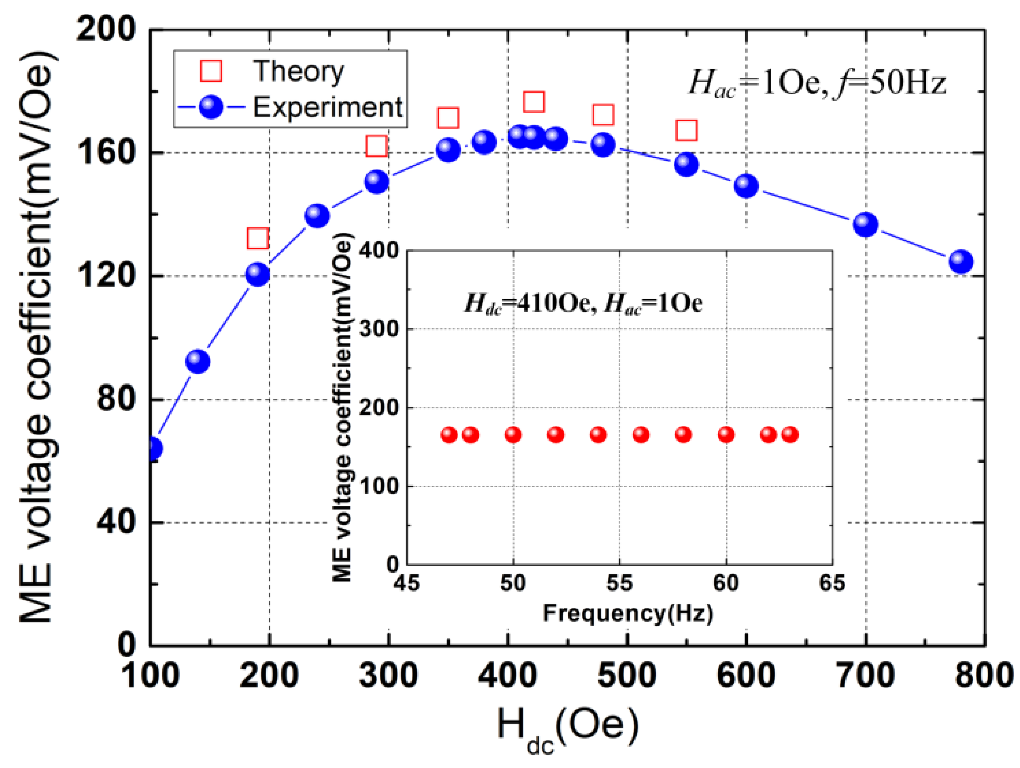
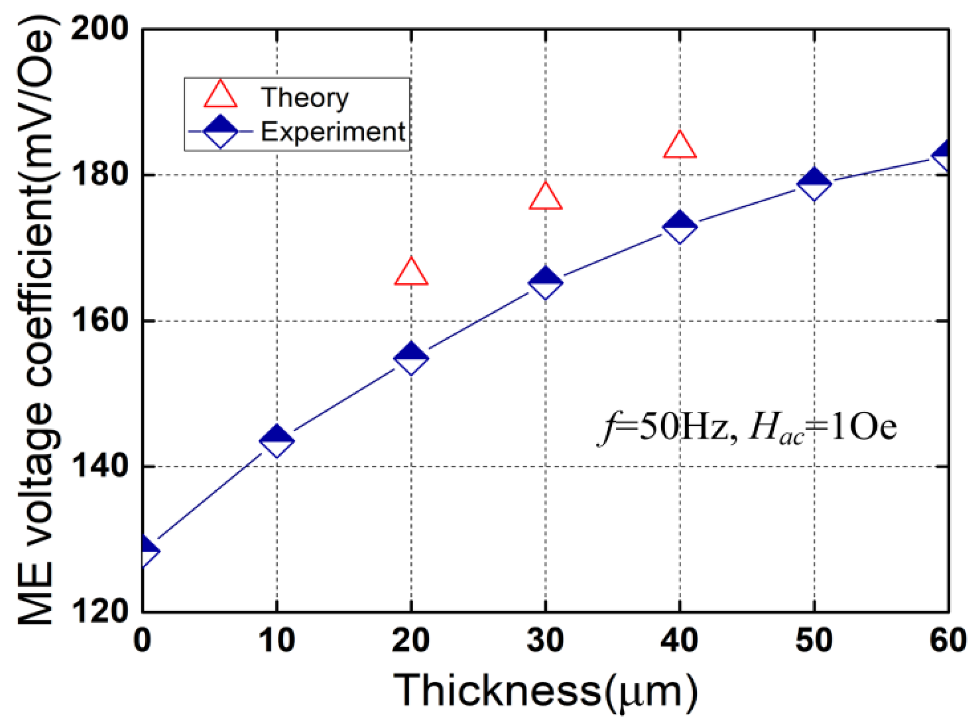
3. Results and Discussions

To validate the performances of the presented ME heterostructure, experiments were performed using a fabricated prototype. The prototype was fabricated according to the following procedure. (1) The components of the heterostructure were cleaned utilizing propanone. (2) The rectangular retaining plate (29 mm × 6 mm × 1.2 mm) and the piezoelectric plates (shear-mode PZT-5A with the dimension of 12 mm × 6 mm × 1 mm for each plate) were bonded using insulate epoxy adhesive. (3) The T-shaped retaining plates (aluminium alloy 6061) were bonded with the PZT-5A plates. (4) The magnetostrictive plates (Terfenol-D with the dimension of 20 mm × 6 mm × 2 mm for each plate and lm = 14 mm) are bonded with the T-shaped retaining plates using insulate epoxy adhesive according to Figure 1. (5) The high-permeability films were glued together with the Terfenol-D plates. For each T-shaped retaining plate, the dimension of the base is 12 mm × 6 mm × 0.8 mm and the size of the centrally bulged part is 3 mm (along the 3-direction) × 6 mm (along the 2-direction in the coordinate system of the PZT-5A) × 0.8 mm. The other parameters for the calculation of the ME voltage coefficient are d 33 , m e f f = 1.415 × 10⁻⁸ m/A (tf = 30 μm), g15 = 38.2 × 10⁻³ Vm/N, s 33 H = 4 × 10⁻¹¹ m2/N, s 55 D = 25.2 × 10⁻¹² m2/N. The ME voltage coefficient is then estimated to be ~176.6 mV/Oe using Equation (12). The measuring principle for the output voltages of the prototype is shown in Figure 3. An alternating current (AC) power source is used to drive a Helmholtz coil, which produces an alternating magnetic field for the prototype. The induced voltages were measured utilizing a digital storage oscilloscope.
The ME voltage coefficient was measured for different bias magnetic fields (Hdc) at the power-frequency of 50 Hz and an alternating magnetic field (Hac) of 1Oe, and the results are plotted in Figure 4. As shown in Figure 4, the ME voltage coefficient exhibits a nearly linear increase for Hdc < 200 Oe and attains a maximum value of 165.2 mV/Oe at the optimal Hdc of 410 Oe, which corresponds to the maximum magnetostriction of the Terfenol-D. The measured ME voltage coefficient is in good agreement with the calculated result (~176.6 mV/Oe). The ME voltage coefficient (165.2 mV/Oe) is larger than those of the traditional ME laminate composites using PZT [31,32,33]. For example, the ME voltage coefficient is 56 mV/Oe for the longitudinal-transverse (LT) mode [31] and is 86 mV/Oe for longitudinal magnetized/longitudinal polarized (L-L) mode [32]. The ME voltage coefficient near the power frequencies (50 Hz and 60 Hz) is shown in the inset of Figure 4, and a flat response is observed. The nearly linear response of the ME voltage coefficient to the bias magnetic field within the low-field range demonstrates the potential application prospect of the proposed device for use in DC magnetoelectric sensors.
Figure 5 plots the ME voltage coefficient as a function of the thickness of the high-permeability film (tf) at the frequency of 50 Hz and under the alternating magnetic field of 1 Oe peak. As shown in Figure 5, the ME voltage coefficient is 128.39 mV/Oe for tf = 0 (without high-permeability films), and increases from 143.5 mV/Oe to 182.64 mV/Oe as the thickness tf is increased from 10 μm to 60 μm (Δtf = 10 μm). The ME voltage coefficient for tf = 60 μm is ~1.42 times larger than that for tf = 0 μm. The theoretical result for tf = 30 μm is ~176.6 mV/Oe, which is in good agreement with the measured result (165.2 mV/Oe) with the error of ~6.9%. The main reason for the increase in the ME voltage coefficient is presented as follows. With the increasing of the thickness of the high-permeability film (tf), the amplitude of the stress T increases, resulting in an increase in the piezomagnetic coefficient ( d 33 , m e f f ) as well as the ME voltage coefficient (αV).
Figure 6 shows the open-circuit RMS voltage of the ME heterostructure versus the alternating magnetic field (peak value) at the bias magnetic field Hdc = 410 Oe and the power-frequency of 50 Hz. As can be observed from Figure 6, the RMS voltage nearly linearly increases from 0.58 V to 3.47 V when Hac increases from 5 Oe to 30 Oe (the theoretical RMS voltage increases from ~0.624 V to ~3.75 V). The theoretical values match the experimental results well with the maximum error < 9%. It can be observed from the inset of Figure 6 that the RMS voltage exhibits a good linear relationship with the alternating magnetic field below 1 Oe. The results demonstrate that the proposed ME heterostructure with strong response to the applied alternating magnetic field is feasible to be used as an energy harvester for the stray power-frequency magnetic field.
The load voltages were measured by utilizing different external load resistances under Hac = 30 Oe (Hdc = 410 Oe), and the powers are obtained based on the following formula
P = V L 2 R L ,
where VL is the voltage across the load resistance RL. The resulting powers for various load resistances are plotted in Figure 7. As can be observed from Figure 7, an approximate linear increase is observed below 200 kΩ. The output power attains a maximum value of 8.69 μW across the load resistance of 693 kΩ. As expected, the power decreases with the load resistance when RL > 693 kΩ. The theoretical maximum output power obtained from Equation (18) is ~10.05 μW with a matching load resistance of 699 kΩ, which verifies the experimental result.
Figure 8 plots the maximum output powers for various alternating magnetic fields. As can be observed from Figure 8, the power of the device with high-permeability films (tf = 30 μm) increases from 0.96 μW to 8.69 μW nearly in a quadratic relationship when Hac varies from 10 Oe to 30 Oe (the theoretical power increases from ~1.114 μW to ~10.05 μW). Larger maximum powers can be obtained when the high-permeability films are used (e.g., the maximum power for tf = 30 μm is ~1.62 times larger than that for tf = 0 μm under Hac = 25 Oe), indicating that more 50 Hz magnetic field energy can be converted into electrical energy by using high-permeability films, which is of importance for the design of the non-resonant magnetic field energy harvester.

4. Conclusions

In summary, a ME heterostructure exploring the shear piezoelectric effect of the piezoelectric material is proposed to extract energy from the stray power-frequency magnetic field. Four piezoelectric plates are used to improve the total equivalent capacitance. The piezoelectric plates of the device deform in the d15 mode owing to the magnetostriction of the Terfenol-D, which produce a voltage proportional to the applied alternating magnetic field. The utilization of the high-permeability films helps to improve the piezomagnetic coefficient, which results in an enhancement of the ME voltage coefficient. The working principle under the external alternating magnetic field was stated and a theoretical analysis was conducted. A prototype was fabricated and experimentally characterized. An enhanced ME voltage coefficient of 165.2 mV/Oe is obtained at 50 Hz, which matches the theoretical result well. The feasibility of the device for harvesting 50 Hz magnetic field energy was verified. A maximum power of 8.69 μW is obtained at 30 Oe. Optimization of the ME heterostructure is achievable. The ME voltage coefficient and the maximum power can be further enhanced by optimizing the materials (e.g., adopting shear-mode PMN-PT) and the structural parameters of the device.

Funding

This work is supported by the National Natural Science Foundation of China (Grant No. 61761001).

Data Availability Statement

All relevant data are available from the author upon reasonable request.

Conflicts of Interest

The author declares no conflict of interest.

References

  1. Zhang, Q.; Liu, X.; Chaker, M.; Ma, D. Advancing graphitic carbon nitride-based photocatalysts toward broadband solar energy harvesting. ACS Mater. Lett. 2021, 3, 663–697. [Google Scholar] [CrossRef]
  2. Zhou, Z.; Qin, W.; Zhu, P. Harvesting acoustic energy by coherence resonance of a bi-stable piezoelectric harvester. Energy 2017, 126, 527–534. [Google Scholar] [CrossRef] [Green Version]
  3. Liu, G.S.; Peng, Y.Y.; Liu, M.H.; Zou, X.Y.; Cheng, J.C. Broadband acoustic energy harvesting metasurface with coupled Helmholtz resonators. Appl. Phys. Lett. 2018, 113, 153503. [Google Scholar] [CrossRef] [Green Version]
  4. Ge, M.; Li, Z.; Zhao, Y.; Xuan, Z.; Li, Y.; Zhao, Y. Experimental study of thermoelectric generator with different numbers of modules for waste heat recovery. Appl. Energy 2022, 322, 119523. [Google Scholar] [CrossRef]
  5. Zhao, Y.; Fan, Y.; Li, W.; Li, Y.; Ge, M.; Xie, L. Experimental investigation of heat pipe thermoelectric generator. Energy Convers. Manage. 2022, 252, 115123. [Google Scholar] [CrossRef]
  6. Zhou, N.; Hou, Z.; Zhang, Y.; Cao, J.; Bowen, C.R. Enhanced swing electromagnetic energy harvesting from human motion. Energy 2021, 228, 120591. [Google Scholar] [CrossRef]
  7. He, W.; Liu, S. A magnetoelectric energy harvester for low-frequency vibrations and human walking. J. Magn. Magn. Mater. 2022, 542, 168609. [Google Scholar] [CrossRef]
  8. He, W. A Piezoelectric Heterostructure Scavenging Mechanical Energy from Human Foot Strikes. Micromachines 2022, 13, 1353. [Google Scholar] [CrossRef]
  9. Zhang, Y.; Wang, T.; Luo, A.; Hu, Y.; Li, X.; Wang, F. Micro electrostatic energy harvester with both broad bandwidth and high normalized power density. Appl. Energy 2018, 212, 362–371. [Google Scholar] [CrossRef]
  10. Huang, X.; Zhang, C.; Dai, K. A Multi-Mode Broadband Vibration Energy Harvester Composed of Symmetrically Distributed U-Shaped Cantilever Beams. Micromachines 2021, 12, 203. [Google Scholar] [CrossRef]
  11. Zhou, J.; Zhao, X.; Wang, K.; Chang, Y.; Xu, D.; Wen, G. Bio-inspired bistable piezoelectric vibration energy harvester: Design and experimental investigation. Energy 2021, 228, 120595. [Google Scholar] [CrossRef]
  12. Qian, M.; Li, Z.; Fan, L.; Wang, H.; Xu, J.; Zhao, W.; Huang, F. Ultra-light graphene tile-based phase-change material for efficient thermal and solar energy harvest. ACS Appl. Energy Mater. 2020, 3, 5517–5522. [Google Scholar] [CrossRef]
  13. Maharjan, P.; Bhatta, T.; Rasel, M.S.; Salauddin, M.; Rahman, M.T.; Park, J.Y. High-performance cycloid inspired wearable electromagnetic energy harvester for scavenging human motion energy. Appl. Energy 2019, 256, 113987. [Google Scholar] [CrossRef]
  14. Mi, J.; Li, Q.; Liu, M.; Li, X.; Zuo, L. Design, modelling, and testing of a vibration energy harvester using a novel half-wave mechanical rectification. Appl. Energy 2020, 279, 115726. [Google Scholar] [CrossRef]
  15. Bhuiyan, R.H.; Dougal, R.A.; Ali, M. A miniature energy harvesting device for wireless sensors in electric power system. IEEE Sens. J. 2010, 10, 1249–1258. [Google Scholar] [CrossRef] [Green Version]
  16. Leland, E.S.; Wright, P.K.; White, R.M. Energy scavenging power sources for household electrical monitoring. In Proceedings of the The Sixth International Workshop on Micro and Nanotechnology for Power Generation and Energy Conversion Applications, Berkeley, CA, USA, 9 November–1 December 2006; pp. 165–168. [Google Scholar]
  17. He, W.; Lu, Y.; Zhang, J.; Qu, C.; Che, G.; Peng, J. Energy harvesting from stray power-frequency magnetic field employing a piezoelectric unimorph based heterostructure. Eur. Phys. J. Appl. Phys. 2016, 73, 30903. [Google Scholar] [CrossRef]
  18. Li, M.; Wen, Y.; Li, P.; Yang, J. A resonant frequency self-tunable rotation energy harvester based on magnetoelectric transducer. Sens. Actuators A Phys. 2013, 194, 16–24. [Google Scholar] [CrossRef]
  19. He, W.; Qu, C. A magnetically levitated magnetoelectric vibration generator using a Halbach array. Sens. Actuators A Phys. 2020, 315, 112301. [Google Scholar] [CrossRef]
  20. He, W.; Li, P.; Wen, Y.; Zhang, J.; Yang, A.; Lu, C. A noncontact magnetoelectric generator for energy harvesting from power lines. IEEE Trans. Magn. 2014, 50, 8204604. [Google Scholar] [CrossRef]
  21. He, W.; Li, P.; Wen, Y.; Zhang, J.; Yang, A.; Lu, C. Energy harvesting from two-wire power cords using magnetoelectric transduction. IEEE Trans. Magn. 2014, 50, 4004805. [Google Scholar] [CrossRef]
  22. Chen, L.; Li, P.; Wen, Y. Enhanced magnetoelectric effects in laminate composites of Terfenol-D/Pb (Zr, TiO)3 with high-permeability FeCuNbSiB ribbon. Smart Mater. Struct. 2010, 19, 115003. [Google Scholar] [CrossRef]
  23. Wang, Y.; Hasanyan, D.; Li, J.; Viehland, D.; Luo, H. Shear-mode magnetostrictive/piezoelectric composite with an enhanced magnetoelectric coefficient. Appl. Phys. Lett. 2012, 100, 202903. [Google Scholar] [CrossRef] [Green Version]
  24. Ding, B.; Ma, T.; Hua, L.; Hu, J.; Zhang, M.; Du, J. Magnetoelectric effects in shear-mode magnetostrictive/piezoelectric composite with a Z-type structure. Mech. Adv. Mater. Struc. 2022, 1–8. [Google Scholar] [CrossRef]
  25. Bi, K.; Wang, Y.G.; Pan, D.A.; Wu, W. Large magnetoelectric effect in mechanically mediated structure of TbFe2, Pb(Zr,Ti)O3, and nonmagnetic flakes. Appl. Phys. Lett. 2011, 98, 133504. [Google Scholar] [CrossRef] [Green Version]
  26. Xu, Y.; Jiang, Z.S.; Wang, Q.; Xu, X.; Sun, D.; Zhou, J.; Yang, G. Three dimensional magnetostatic field calculation using equivalent magnetic charge method. IEEE Trans. Magn. 1991, 27, 5010–5012. [Google Scholar] [CrossRef]
  27. Zheng, X.J.; Liu, X.E. A nonlinear constitutive model for Terfenol-D rods. J. Appl. Phys. 2005, 97, 053901. [Google Scholar] [CrossRef]
  28. Virkar, A.V.; Huang, J.L.; Cutler, R.A. Strengthening of Oxide Ceramics by Transformation-Induced Stress. J. Am. Ceram. Soc. 1987, 70, 164–170. [Google Scholar] [CrossRef]
  29. Engdahl, G. Handbook of Giant Magnetostrictive Materials; Academic Press: San Diego, CA, USA, 2000; Chapter 2. [Google Scholar]
  30. Ikeda, T. Fundamentals of Piezoelectricity; Oxford University Press: Oxford, UK, 1990; pp. 38–39. [Google Scholar]
  31. Dong, S.; Li, J.F.; Viehland, D. Characterization of magnetoelectric laminate composites operated in longitudinal-transverse and transverse–transverse modes. J. Appl. Phys. 2004, 95, 2625–2630. [Google Scholar] [CrossRef] [Green Version]
  32. Dong, S.; Li, J.F.; Viehland, D. Longitudinal and transverse magnetoelectric voltage coefficients of magnetostrictive/piezoelectric laminate composite: Experiments. IEEE Trans. Ultrason. Ferroelectr. Freq. Control 2004, 51, 794–799. [Google Scholar] [CrossRef]
  33. Yang, F.; Wen, Y.M.; Li, P.; Zheng, M.; Bian, L.X. Resonant magnetoelectric response of magnetostrictive/piezoelectric laminate composite in consideration of losses. Sens. Actuators A Phys. 2008, 141, 129–135. [Google Scholar] [CrossRef]
Figure 1. Schematic diagram and picture of the proposed shear-mode ME heterostructure.
Micromachines 13 01882 g001
Figure 2. Deformations of the Terfenol-D plates and the piezoelectric plates under operation.
Micromachines 13 01882 g002
Figure 3. Measurement principle for the induced voltages of the fabricated prototype.
Micromachines 13 01882 g003
Figure 4. ME voltage coefficient as a function of the bias magnetic field under the alternating magnetic field of 1 Oe peak and at the power frequency of 50 Hz. The inset shows the frequency response of the measured ME voltage coefficient near the power frequencies under an alternating magnetic field of 1 Oe peak.
Micromachines 13 01882 g004
Figure 5. ME voltage coefficient versus the thickness of the high-permeability film.
Micromachines 13 01882 g005
Figure 6. Open-circuit RMS voltage as a function of the applied alternating magnetic field. The inset shows the measured results below 1 Oe.
Micromachines 13 01882 g006
Figure 7. Output power versus load resistance under the alternating magnetic field of 30 Oe.
Micromachines 13 01882 g007
Figure 8. Maximum output power versus the applied alternating magnetic field.
Micromachines 13 01882 g008
Publisher’s Note: MDPI stays neutral with regard to jurisdictional claims in published maps and institutional affiliations.

