Article

Metamaterial-Inspired Electrically Compact Triangular Antennas Loaded with CSRR and 3 × 3 Cross-Slots for 5G Indoor Distributed Antenna Systems

by
Arshad Karimbu Vallappil
1,2,*,
Bilal A. Khawaja
2,3,*,
Mohamad Kamal A. Rahim
1,
Muhammad Naeem Iqbal
1 and
Hassan T. Chattha
4
1
Advance RF and Microwave Research Group (ARFMRG), School of Electrical Engineering, Faculty of Engineering, Universiti Teknologi Malaysia, UTM Johor Bahru, Johor Bahru 81310, Johor, Malaysia
2
Department of Electrical Engineering, Faculty of Engineering, Islamic University of Madinah, P.O. Box 170, Madinah 41411, Saudi Arabia
3
Department of Electrical Engineering, PN-Engineering College (PNEC), National University of Sciences and Technology (NUST), Karachi 75104, Pakistan
4
Department of Information Technology, Focus College, Kelowna, BC V1Y 8A6, Canada
*
Authors to whom correspondence should be addressed.
Micromachines 2022, 13(2), 198; https://doi.org/10.3390/mi13020198
Submission received: 30 December 2021 / Revised: 22 January 2022 / Accepted: 24 January 2022 / Published: 27 January 2022
(This article belongs to the Special Issue Miniaturized Microwave Components and Devices)

Abstract

:
In this article, two distinct kinds of metamaterial (MTM) antennas are proposed for fifth-generation (5G) indoor distributed antenna systems (IDAS). Both antennas operate in the sub-6 GHz 5G band, i.e., 3.5 GHz. The antenna’s radiating structure is based on a combination of triangular and rectangular patches, as well as two complementary split-ring resonators (CSRR) unit-cells etched on the top layer. The bottom layer of the first MTM antenna is a complete ground plane, while the bottom layer of the second MTM antenna is etched by a 3 × 3 cross-slot MTM structure on the ground plane. The use of these structures on the ground plane improves the antenna bandwidth. The proposed antennas are designed using two different substrates i.e., a high-end Rogers thermoset microwave materials (TMM4) substrate (h = 1.524 mm/εr = 4.5/tan δ = 0.002) and a low-end flame-resistant (FR4) epoxy glass substrate (h = 1.6 mm/εr = 4.3/tan δ = 0.025), respectively. The antenna designs are simulated using CST microwave studio, and in the end, the antenna fabrication is performed using FR4 substrate, and the results are compared. Furthermore, parametric analysis and comparative studies are carried out to investigate the performance of the designed antennas. The simulated and measured results are presented for various parameters such as return-loss, gain, and radiation pattern. The two MTM antennas have an overall dimension of 18 × 34 mm2, demonstrating that the proposed design is 60 percent smaller than a standard microstrip patch antenna (MPA). The two proposed MTM antenna designs with complete ground plane and 3 × 3 cross-slot MTM on the bottom layer using FR4 substrate have a measured gain/bandwidth characteristic of 100 MHz/2.6 dBi and 700 MHz/2.3 dBi, respectively.

1. Introduction

The increasing number of individuals using mobile phones, tablets, and other handheld and wearable wireless devices has accelerated the development of wireless communication technologies and systems, including antennas. In particular, for next-generation communications, which require a lightweight antenna with high-gain to improve system performance, the compact antenna must have a high-gain and a large bandwidth to meet the increased demand for excellent communication quality with millions of users.
The demand for high-speed and broadband data services among mobile users is skyrocketing, and more than 80% of mobile data traffic is handled indoors, such as in commercial buildings and airports [1]. As a result, indoor distributed antenna systems (IDAS) are becoming increasingly vital for providing wireless communication coverage in high-traffic and dense indoor environments [2]. Because the majority of IDAS antennas are installed on the ceilings or walls of indoor spaces, they must have a low-profile, large bandwidth, and high-gain [3].
The printed microstrip patch antenna (MPA) is a suitable choice because of its low-profile, but it has the drawback of having a narrow bandwidth [3]. Different types of broadband printed antennas have been proposed to improve bandwidth for broadband applications, including modified fractal antennas [4,5], planar elliptical antennas [6,7,8], notched trapezoidal monopole antennas [9], dual band-notched circular ring antennas [10], a half-disc and a half-ellipse antenna [11], and a back-to-back triangular-shaped patch antenna [12]. However, all the previously proposed antennas suffer from low-gain at low frequency. As a result, low-profile broadband antennas with good gain that can cover the whole sub-6 GHz 5G frequency band are in high demand [1]. A metamaterial (MTM) antenna design technique, on the other hand, can be utilized to overcome the limits of traditional MPA antenna design schemes and is often focused on enhancing antenna performance, bandwidth, weight, directivity, efficiency, and other parameters [13,14,15,16].
In recent years, the scientific community has shown an increased interest in the study of MTMs [13,14,15,16]. The MTMs are the artificial, effectively homogeneous electromagnetic structures that exhibit novel electromagnetic properties that are not typically found in nature [17,18,19]. A structure whose average cell size p is much smaller than the quarter wavelength (p < λg/4) is known as an effectively homogeneous structure. MTMs are a type of artificially constructed material dependent on periodical structures. These materials have negative permittivity (ε) and permeability (μ) at the same time, thereby known as double negative metamaterials (DNMs) [20,21,22]. In 1999, a scientist named Pendry et al. [23,24] first introduced negative-ε/positive-μ and positive-ε/negative-μ structures. Pendry introduced periodically located metallic thin-wires (TW) to achieve negative permittivity. Later, his team proposed spilt-ring resonators (SRRs) to get negative permeability [23,24]. In [25], Smith et al. combined Pendry’s TW and SRR structures into the composite structure. The TW and SRR structure develops negative-ε and negative-μ, respectively. This leads to generating left-handed-MTM (LH-MTM).
Some researchers focused their studies on the multi-band MTMs. The first kind of multi-band MTMs is based on well-designed metallic patterns, such as the ‘S-shaped’ [26], the ‘H-shaped’ [27], and the ‘Z-shaped’ [28] MTMs. An advanced, well-designed metallic pattern mode is fractal shapes, such as the nested ‘U-shaped’, and the ‘tree-shaped’ [29] MTMs. Another kind of multi-band MTMs is implemented with a combination of different single-band MTM units. In [30], similar patterns are printed on different substrates, while in [31], SRRs with different opening directions are printed on 3-layers substrates.
A few other researchers focused on the studies on tunable MTMs. There are multiple methods to implement tunable characteristics, such as loading varactors [32], applying ferrite-slabs [33] or liquid-crystals [34], and mechanically changing the structures [35]. Among these methods, varactor-loaded tunability is the most applicable solution. Some researchers focused on the studies to improve the gain of antenna by using MTM structures. The MTM structure has been used as a superstrate or loading MTM around the radiating patch. Other researchers used the MTM as a defective ground structure to improve the overall bandwidth of the antenna [36]. MTM structure properties enable a lot of applications in microwave and optical frequencies, including absorbers [37], energy harvesting [38], meta-lenses [39], and cloaking [40].
Therefore, this paper presents two MTM antenna designs using a complementary SRR (CSRR) and Cross-slot structure. The radiating structure of the antenna is designed based on the combination of triangular and rectangular patches and two CSRR unit-cells etched on the top layer. For the first antenna, the bottom layer is a complete ground plane, i.e., perfect electric conductor, and for the second antenna, the bottom layer is etched by 3 × 3 cross-slots MTM on the ground plane. The two antennas have been designed using two different substrates, i.e., a low-end flame-resistant (FR4) glass epoxy substrate and a high-end Rogers TMM4 substrate. Both antenna designs are compared in terms of performance, such as gain, bandwidth, radiation pattern, and S-parameters. The proposed antennas are operating at 3.5 GHz. Many enticing features of the proposed antenna include large bandwidth, high gain, and directional radiation pattern, making them an ideal candidate for 5G indoor distributed antenna systems (IDAS). The rest of this article is carried out as follows: The MTM unit-cell design, proposed antenna design configuration, and its simulation results, including parametric analysis, are briefly discussed in Section 2. Section 3 concisely discussed the analysis of the proposed design with the different substrates. The two MTM antenna simulated and measured results, including return-loss (S11), E- & H-plane radiation patterns, and gain characteristics, are discussed and summarized in Section 4. Section 5 compares the results of the two proposed MTM antennas with existing research articles and provides its findings, while Section 6 draws conclusions.

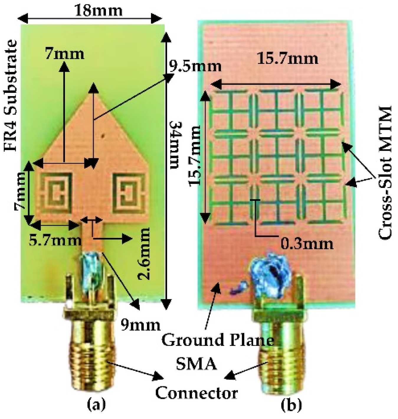
2. Proposed Antenna Design

The proposed antenna design starts with a triangular patch of side-length 14 mm, as shown in Figure 1a. The resonant frequency can be calculated based on Equation (1) without the fringing effect [41]. The parameters c, a, εr represents the velocity of light, triangular patch side-length, and dielectric constant, respectively.
f r = 2 c 3 a ε r
The resonant frequency may be determined with better accuracy if a and εr in the above equation are replaced by effective dielectric constant εeff and aeff, which are given by [42]. Finally, as per the calculation, the triangular patch antenna (TPA) resonates at 7 GHz, and the results are verified by simulating the TPA using CST microwave studio based on FR4 substrate having an εr and thickness (h) of 4.3 and 1.6 mm, respectively, as shown in Figure 2.
ε r e f f = ( ε r + 1 ) 2 + ( ε r 1 ) 2 ( 1 + 12 × h W ) 1 2 = 3.72
a e f f = a + h ε r = 14.77
f r = 2 c 0 3 a e f f ε r e f f = 7   GHz
The next step is to design a rectangular patch antenna (RPA) having the same width (W) of TPA and length (L) of 14 mm and 7 mm, respectively, as shown in Figure 1b. In order to get the same width of TPA, we selected 9 GHz as the resonating frequency for the RPA, and the simulated results are illustrated in Figure 2. In the third step, we combined TPA and RPA, as shown in Figure 1c. The 3.5 GHz frequency band has been chosen in this study for 5G technology [43]. Moreover, the 700 MHz, 3.5 GHz, and 26/28 GHz have also been identified as potential frequency bands for the initial deployment of 5G technology in Malaysia [44]. The mathematical resonant frequency of TPA (f1) and RPA (f2) is 7 GHz and 9 GHz, respectively. The new resonant frequency after the combination of TPA and RPA will be (f1 + f2)/4, i.e., is equal to 4 GHz. After an in-depth parametric simulation study using CST microwave studio, it can be seen that the combined structure resonates at 3.75 GHz, as shown in Figure 2. In order for the comparison, the size of the individual RPA to resonate at 3.75 GHz will be 24.5 × 19.5 mm2. So, the total area of individual RPA will be 478 mm2. The proposed antenna patch has a total area of 195 mm2, which indicates a size reduction of 60% compared to the individual RPA.

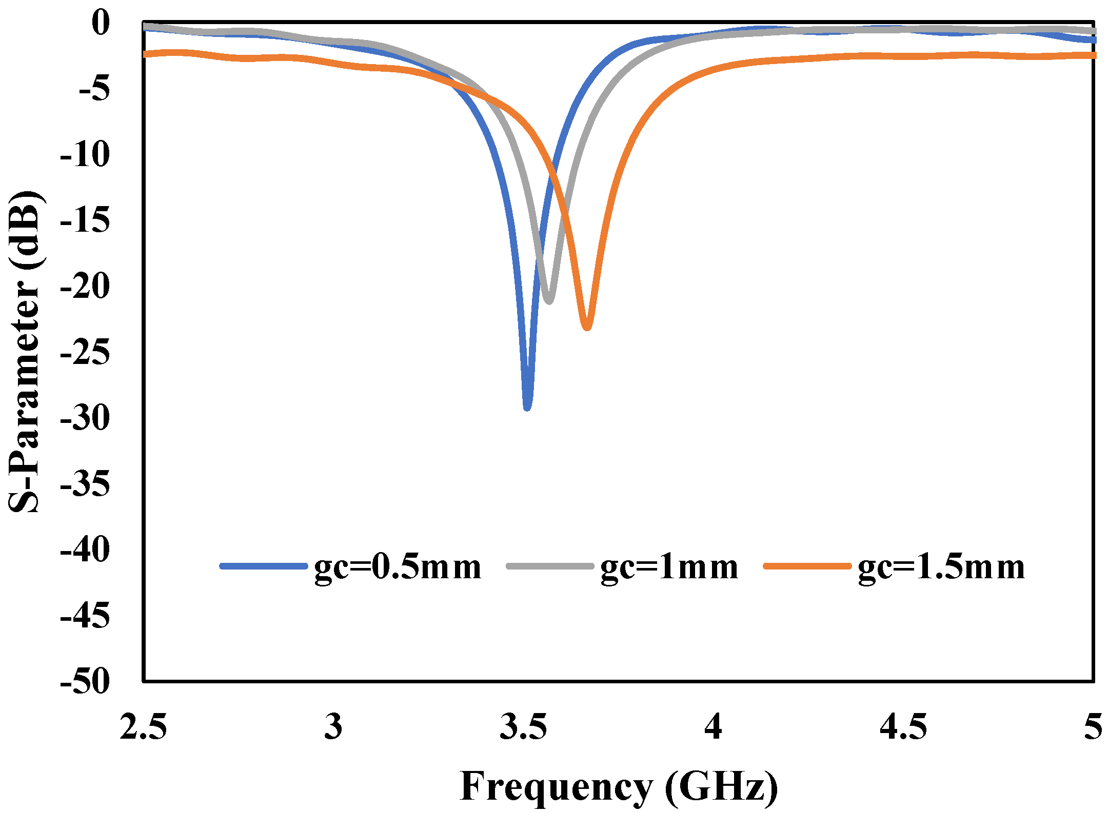
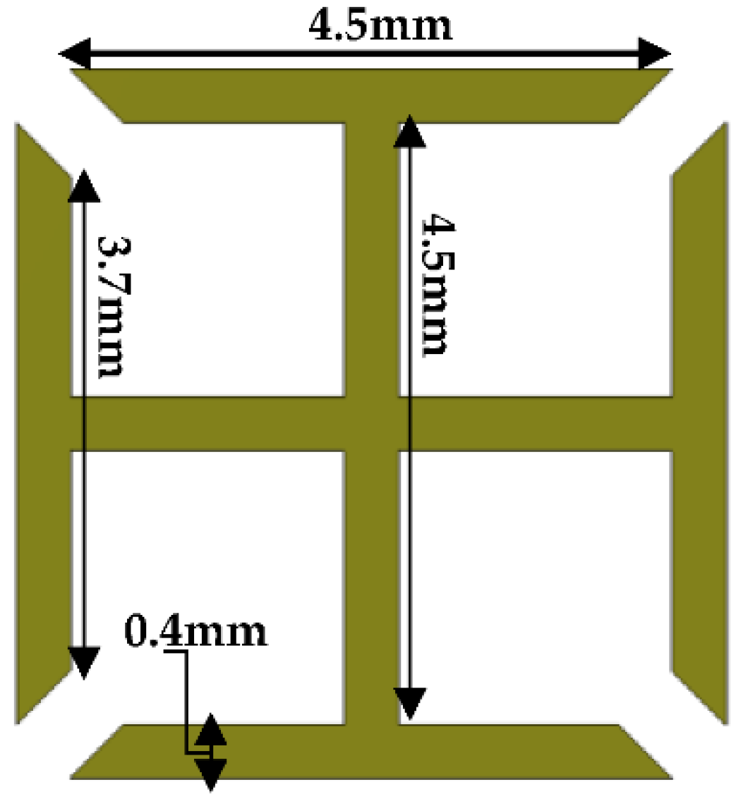
2.1. CSRR MTM Structure Inserted to Proposed Antenna

A CSRR MTM structure has been inserted into the proposed antenna’s radiating patch [45]. The structure and dimension of the CSRR structure used in this study is shown in Figure 3. The overall dimension of the proposed antenna after inserting the CSRR structure is also shown in Figure 3. The insertion of the CSRR structure shifts the center frequency of the proposed antenna to 3.5 GHz, as shown in Figure 4. The return-loss (S11) graph is plotted by varying the dimension of the CSRR parameter ‘gc’ to 0.5 mm, 1 mm, and 1.5 mm, respectively, as shown in Figure 4. From the graph, it can be observed that the frequency is shifted to the left by reducing the gap ‘gc’ and shifted to the right by increasing the gap. Finally, the desired results were achieved for the CSRR parameters at gc = 0.5 mm, tc = 0.5 mm, and sc = 0.5 mm. The results are highlighted with a solid blue-line in Figure 4, and it can be observed that the proposed antenna shows a bandwidth of 150 MHz and a return-loss of −30 dB at 3.5 GHz. The optimized dimensions of the CSRR unit-cell are shown in Table 1.

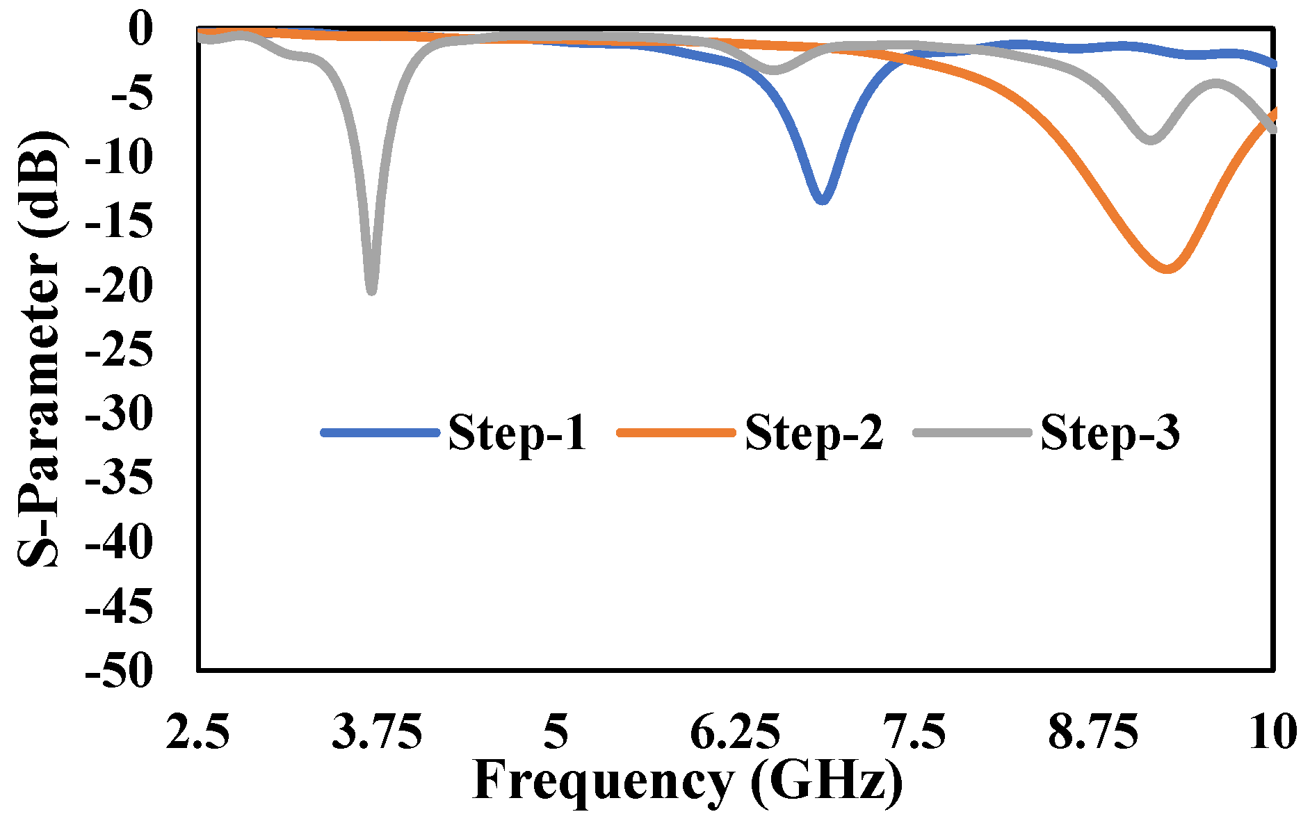
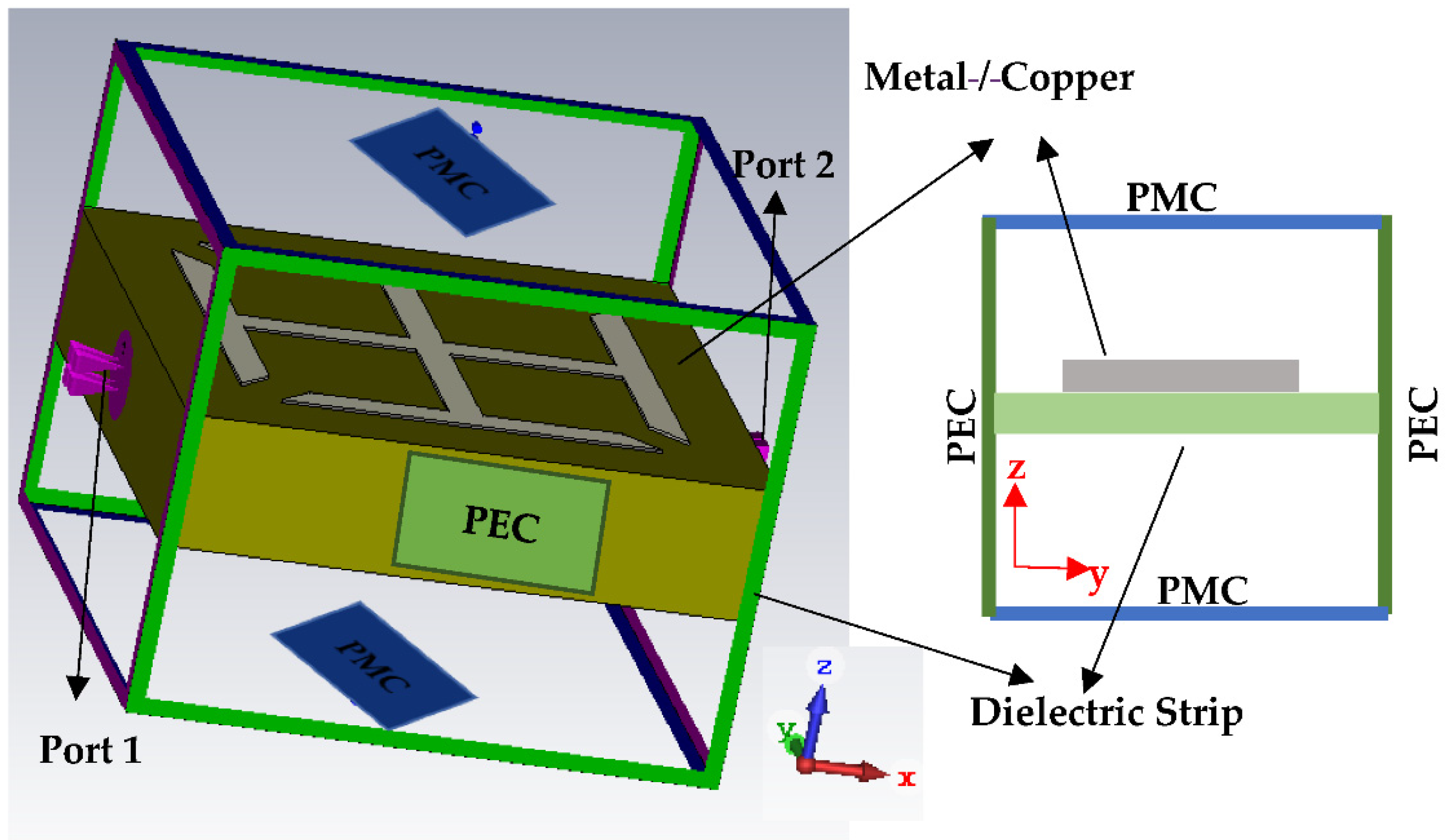
2.2. Metallic-Cross Metamaterial Structure

The proposed metallic-cross MTM unit-cell is initially simulated by putting it in a rectangular waveguide to investigate the MTM properties. The structure of the proposed metallic-crosst MTM unit-cell is shown in Figure 5. The proposed MTM unit-cell used to load in the ground plane of the antenna, is expected to demonstrate the LH-MTM properties. For this purpose, a metallic-cross unit-cell printed on FR4 substrate has been designed and simulated as MTM with the help of CST Microwave studio. In this case, perfect boundary conditions have been applied to a unit-cell comprising only one metallic-cross, having two sides of the unit-cell (along the y-axis) with a perfect electric conductor (PEC) as a boundary condition, and the other two (along the z-axis) with a perfect magnetic conductor (PMC), as can be seen in Figure 6. The remaining two sides of the unit-cell (along the x-axis) are used as wave ports for excitation and radiation purposes. Further details on boundary conditions and excitations assignment to a unit-cell are shown in Figure 6.
The S-Parameter response of the unit-cell is shown in Figure 7. It can be observed from Figure 7 that S11 and S21 parameters cross each other at 2 GHz and 4.8 GHz, respectively. This shows that the unit-cell structure has a bandgap between 2–4.8 GHz where electromagnetic waves are reflected, which makes the structure to have negative material properties [46,47].
Furthermore, effective permeability (μeff) and permittivity (εeff) of an equivalent MTM unit-cell are determined from Nicolson-Ross-Weir (NRW) approach [48]. The effective electromagnetic parameters (μeff and εeff) are generated from Scattering parameters, i.e., S11 and S21. The μeff and εeff has been calculated using the Equations (5)–(8) and its response with respect to frequency is shown in Figure 8. The values, V1 and V2 indicate the summation and difference of S-parameters. The V1 and V2 are calculated from Equations (5) and (6), respectively.
V 1 = S 21 + S 11  
V 2 = S 21 S 11
μ e f f = 2 j k 0 h 1 V 2 1 + V 2  
ε e f f = 2 j k 0 h 1 V 1 1 + V 1
where, k0 is wave number in free space and is equated to ω/c, ω is the radian frequency and c = 2πf, c is the speed of light = 3 × 10⁸ m/s, μeff is the effective permeability of equivalent MTM, εeff is the effective permittivity of equivalent MTM, and h is the thickness/height of the substrate.

2.3. Cross-Slot Metamaterial Structure Etched in the Ground Plane of Proposed Antenna

A 3 × 3 metallic-cross MTM structure has been etched in the ground plane of the proposed antenna to improve the bandwidth, as shown in Figure 9. After etching in the ground plane, this metallic-cross will be referred to as cross-slot MTM structure. The structure and dimension of the cross-slot MTM unit-cell are shown previously in Figure 5. A parametric analysis based on the number of cross-slot MTM structures has been investigated. The proposed antenna in Figure 9 without cross-slot MTM in the ground plane resonates at 4.5 GHz with a bandwidth of 150 MHz, as shown in Figure 10. Initially, a 1 × 3 cross-slot MTM structure was etched in the ground plane, which shows a bandwidth of 400 MHz. In order to further improve the bandwidth, a 2 × 3, and 3 × 3 MTM structure analysis was performed by etching in the ground plane. The final antenna design with 3 × 3 cross-slot MTM structure etched in the ground plane is shown in Figure 9b. The Cross-Slot unit-cell etched on the ground layer develops negative ε and µ [49]. The capacitance value of cross-slot unit-cell can be varied by changing the gap between them. By increasing the capacitance value, the bandwidth will improve [50]. So, by increasing the number of cross-slot unit-cell, the bandwidth of the antenna has been improved. From the S-parameter response shown in Figure 10, it was noticed that the bandwidth is gradually increasing as the number of MTM structure etching in the ground plane increases. Figure 10 shows the results of the 1 × 3, 2 × 3, and 3 × 3 MTM structure etched in the ground plane. It can be seen from the results that this MTM antenna design shows the bandwidth/return-loss characteristics of 400 MHz/−26 dB, 575 MHz/−20 dB and 730 MHz/−40 dB, respectively.

3. Analysis of Proposed Design with Different Substrate

After getting the optimized dimensions of both proposed antennas from the simulation study, the return-loss (S11) plots of both MTM antennas are plotted using FR4 and Rogers TMM4 substrate, and the results are summarized in Figure 11. The εr and h of the chosen Rogers TMM4 substrate were 4.5 and 1.524 mm, respectively. It is important to note that both substrates have very similar dielectric permittivity and thickness parameters. The purpose of selecting two different substrates, i.e., a high-end Rogers TMM4 and a low-end FR4 substrate, is to identify which one will provide more gain for the proposed antenna design.
Figure 12a,b shows the E- & H-plane simulated radiation pattern results of the proposed antenna with the complete ground plane by using both FR4 and Rogers TMM4 substrates, which resonates at 3.5 GHz. From Figure 12a,b, it can be observed that the gain is improved from 2.9 dBi to 4.9 dBi by replacing the low-end and lossy FR4 substrate with the high-end Rogers TMM4 substrate. It is clear from this study that the proposed structure will provide high-gain characteristics by replacing the low-cost FR4 with high-end Rogers TMM4 substrate. Similarly, Figure 13a,b shows the E- & H-plane simulated radiation pattern results of the proposed antenna with cross-slot MTM structure etched on the ground plane using both substrates. This structure also exhibits better gain characteristics by replacing the substrate from FR4 with Rogers TMM4. The loss tangent (tan δ) of TMM4 and FR4 substrate are 0.002 and 0.025, respectively [51]. It means the FR4 substrate is a lossy substrate, and its radiation efficiency will always be less than the TMM4 substrate. This is the reason TMM4 substrate has a higher gain than FR4; even the dielectric permittivity and thickness parameters are the same. For the proof-of-concept in this work, the proposed antenna is fabricated using FR4 substrate due to its low-cost nature and easy availability.

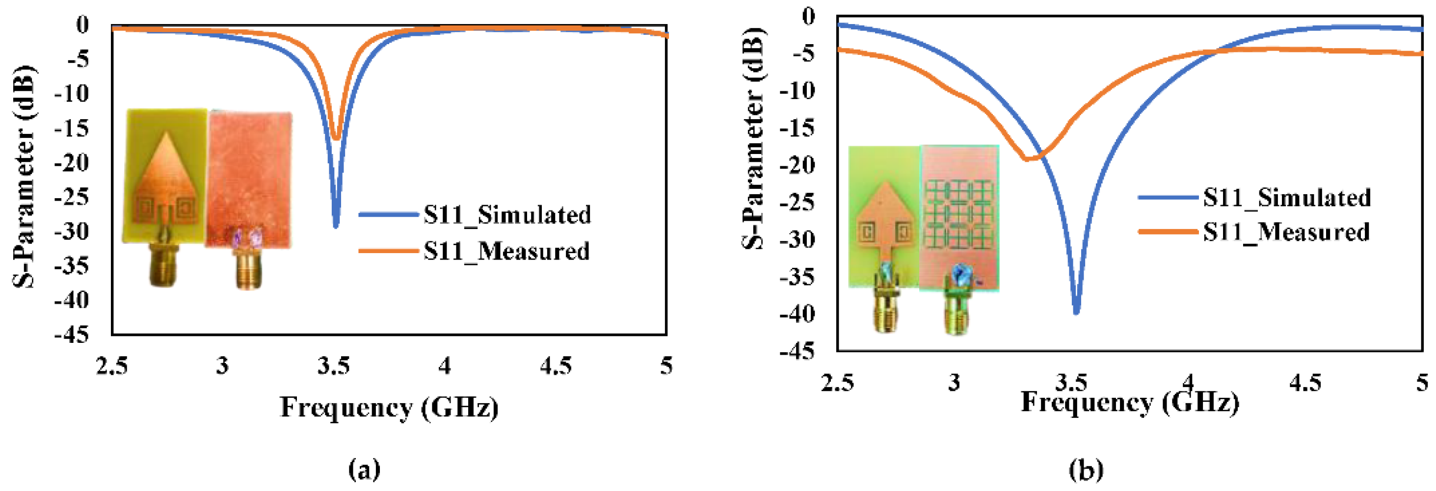
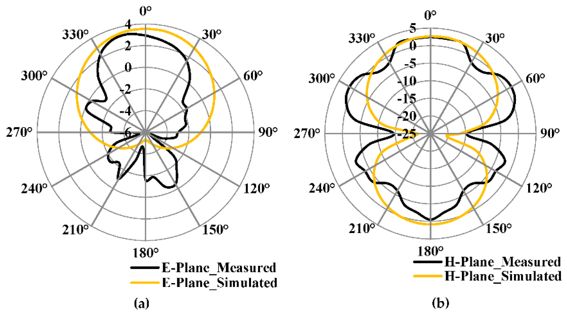
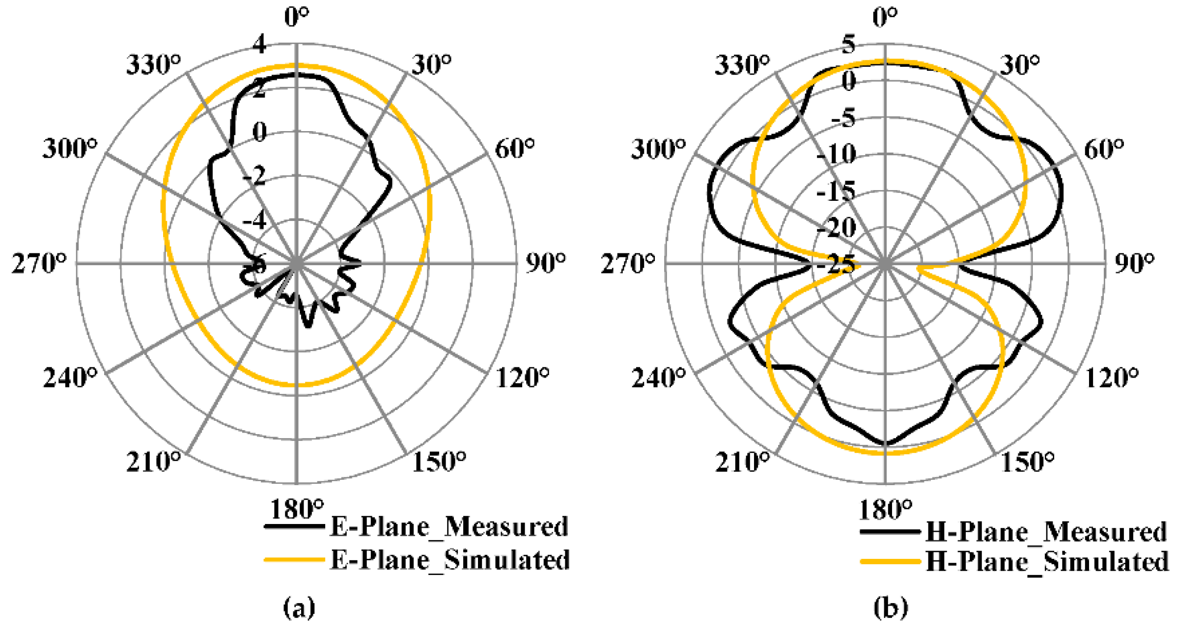
4. Result and Discussion

The top layer in the proposed antenna design is based on the combination of RPA and TPA with CSRR structure, and the bottom layer has been modified by (1) complete ground plane, and (2) ground plane replaced by 3 × 3 cross-slot MTM structure. Figure 14a,b and Figure 15a,b show the fabricated antenna top and bottom layers of the proposed antenna with complete ground plane and proposed antenna with cross-slot MTM structure etched on the ground plane, respectively. The overall dimension of the antenna shows the compactness of the proposed design (18 × 34 mm2). Keysight (Agilent Technologies) FieldFox N9925A vector network analyzer (VNA) was used to conduct the S-parameter measurements of the fabricated antennas.
Figure 16a,b shows the simulated and measured return-loss (S11) of the proposed antenna with (1) complete ground plane or (2) 3 × 3 cross-slot MTM etched on the ground plane. It can be observed from Figure 16a,b that both MTM antennas are resonating at 3.5 GHz and showing a measured return-loss of −16 dB and −19 dB, respectively. The MTM with complete ground plane and cross-slot MTM structure etched on the ground plane has a measured −10 dB bandwidth of 100 MHz (3.46 GHz–3.56 GHz) and 700 MHz (2.96 GHz–3.66 GHz), respectively.
The simulated and measured E- & H-plane radiation patterns proposed antenna with complete are shown in Figure 17a,b. The proposed antenna shows the maximum simulated and measured gain of 2.9 dBi and 2.6 dBi, respectively. From Figure 17a,b, it can be understood that the antenna radiates in the boresight. The measured radiation pattern slightly deviates from 0° as compared to the simulated result.
Figure 18a,b shows the E- and H-plane radiation pattern of the proposed antenna with 3 × 3 cross-slot MTM etched in the ground plane, respectively. It has a maximum simulated and measured gain of 2.5 dBi and 2.3 dBi, respectively, in the E-Plane. It has a side-lobe level of −2 dBi. The H-plane has a maximum simulated and measured gain of 2.45 dBi and 2.3 dBi, respectively. The gain of the fabricated prototype was measured using a standard horn antenna as a reference source.
Figure 19 shows the simulated and measured gain versus frequency graph for both proposed antennas. From the graph, it can be observed that the simulated and measured gain at 3.5 GHz is almost close to each other. The proposed antenna with complete ground plane has a little higher gain as compared to the antenna with a 3 × 3 cross-slot MTM structure. But the bandwidth is more for the antenna with 3 × 3 cross-slot MTM structure.

5. Comparison

Table 2 compares the proposed MTM antenna performance with several other MTM antennas presented in the literature and operating at 3.5 GHz [52,53,54,55,56,57,58]. All MTM antenna sizes and thicknesses in Table 2 are normalized to the free space wavelength λo at the resonant frequency 3.5 GHz. The −10 dB relative bandwidth (BW) of these MTM antennas’ results are summarized in the BW column. Table 2 shows that previous MTM antenna designs either improved the bandwidth [52,53] or gain [54,55,56] or reduced the antenna size [56,57,58]. Although, the proposed MTM antenna based on cross-slot results shows a 60 percent reduction in size and a seven-fold increase in the bandwidth over the conventional MPA design at 3.5 GHz. The gain of the proposed antenna can be further improved by using a high-end Roger’s substrate. Many enticing features of this proposed MTM antenna include large bandwidth, high-gain, and compact size, making them an ideal candidate for the 5G IDAS.

6. Conclusions

A combination of triangular and rectangular patches with two kinds of MTM structure, which includes complementary split-ring resonator (CSRR) on the top layer and 3 × 3 cross-slot MTM on the bottom layer, was proposed in this study. The measured result of the FR4 substrate based proposed antenna with a cross-slot MTM structure etched on the ground plane shows larger bandwidth as compared to the MTM antenna with the complete ground plane. Both the antennas have a gain almost close to each other. Furthermore, when compared to the previous designs in Table 2, the MTM antenna with cross-slot etched on the ground plane exhibits larger bandwidth and better gain. The proposed MTM antenna with a cross-slot structure on the ground plane is considered the most promising candidate for 5G IDAS because of its miniaturized structure and is also considered a good choice for the upcoming 5G applications due to its small size, improved bandwidth, and gain. The gain can be boosted more in the future by adopting a high-end Rogers TMM4 substrate.

Author Contributions

A.K.V., B.A.K. coined the idea, led, supervised, and evaluated the entire project: edited the write-ups, designed, and simulated the proposed antennas. A.K.V., M.K.A.R., M.N.I. performed the experimental measurements. A.K.V. completed the initial draft of the paper; A.K.V., B.A.K., M.K.A.R., M.N.I. and H.T.C. then analyzed, evaluated, and edited the paper. All authors have read and agreed to the published version of the manuscript.

Funding

This research was funded by “Deanship of Scientific Research, Islamic University of Madinah, Madinah, Saudi Arabia, Grant Number 657”.

Acknowledgments

The authors would like to acknowledge the funding from the Deanship of Scientific Research, Islamic University of Madinah, Madinah, Saudi Arabia, under the Research Grant No. 657.

Conflicts of Interest

The authors declare no conflict of interest.

References

  1. Shafique, K.; Khawaja, B.A.; Sabir, F.; Qazi, S.; Mustaqim, M. Internet of Things (IoT) for Next-Generation Smart Systems: A Review of Current Challenges, Future Trends and Prospects for Emerging 5G-IoT Scenarios. IEEE Access 2020, 8, 23022–23040. [Google Scholar] [CrossRef]
  2. Rappaport, T.S.; Xing, Y.; Kanhere, O.; Ju, S.; Madanayake, A.; Mandal, S.; Alkhateeb, A.; Trichopoulos, G.C. Wireless Communications and Applications Above 100 GHz: Opportunities and Challenges for 6G and Beyond. IEEE Access 2019, 7, 78729–78757. [Google Scholar] [CrossRef]
  3. Zhou, L.; Jiao, Y.; Qi, Y.; Weng, Z.; Lu, L. Wideband Ceiling-Mount Omnidirectional Antenna for Indoor Distributed Antenna Systems. IEEE Antennas Wirel. Propag. Lett. 2014, 13, 836–839. [Google Scholar] [CrossRef]
  4. Singhal, S.; Singh, A.K. Modified star-star fractal (MSSF) super-wideband antenna. Microw. Opt. Technol. Lett. 2017, 59, 624–630. [Google Scholar] [CrossRef]
  5. Waladi, V.; Mohammadi, N.; Zehforoosh, Y.; Habashi, A.; Nourinia, J. A Novel Modified Star-Triangular Fractal (MSTF) Monopole Antenna for Super-Wideband Applications. IEEE Antennas Wirel. Propag. Lett. 2013, 12, 651–654. [Google Scholar] [CrossRef]
  6. Manohar, M. Miniaturised low-profile super-wideband Koch snowflake fractal monopole slot antenna with improved BW and stabilised radiation pattern. IET Microw. Antennas Propag. 2019, 13, 1948–1954. [Google Scholar] [CrossRef]
  7. Hussein, M.I.; Hakam, A.; Ouda, M. Planar Ultra-Wideband Elliptical Antenna for Communication Applications. In Proceedings of the 2016 IEEE Wireless Communications and Networking Conference, Doha, Qatar, 3–6 April 2016; pp. 1–5. [Google Scholar]
  8. Liang, X.-L.; Zhong, S.-S.; Wang, W. Elliptical planar monopole antenna with extremely wide bandwidth. Electron. Lett. 2006, 42, 441–442. [Google Scholar] [CrossRef]
  9. Yan, X.-R.; Zhong, S.-S.; Liang, X.-L. Compact printed semi-elliptical monopole antenna for super-wideband applications. Microw. Opt. Technol. Lett. 2007, 49, 2061–2063. [Google Scholar] [CrossRef]
  10. Manohar, M.; Nemani, U.K.; Kshetrimayum, R.S.; Gogoi, A.K. A Novel Super Wideband Notched Printed Trapezoidal Monopole Antenna with Triangular Tapered Feedline. In Proceedings of the 2014 International Conference on Signal Processing and Communications (SPCOM), Bangalore, India, 22–25 July 2014; pp. 1–6. [Google Scholar]
  11. Manohar, M.; Kshetrimayum, R.S.; Gogoi, A.K. A Compact Dual Band-Notched Circular Ring Printed Monopole Antenna for Super wideband Applications. Radioengineering 2017, 26, 64–70. [Google Scholar] [CrossRef]
  12. Dong, Y.; Hong, W.; Liu, L.; Zhang, Y.; Kuai, Z. Performance analysis of a printed super-wideband antenna. Microw. Opt. Technol. Lett. 2009, 51, 949–956. [Google Scholar] [CrossRef]
  13. Wang, Z.; Dong, Y.; Itoh, T. Transmission Line Metamaterial-Inspired Circularly Polarized RFID Antenna. IEEE Antennas Wirel. Propag. Lett. 2020, 19, 964–968. [Google Scholar] [CrossRef]
  14. Vallappil, A.K.; Rahim, M.K.A.; Khawaja, B.A.; Iqbal, M.N. Compact Metamaterial Based $4\times4$ Butler Matrix with Improved Bandwidth for 5G Applications. IEEE Access 2020, 8, 13573–13583. [Google Scholar] [CrossRef]
  15. Cao, W.; Ma, W.; Peng, W.; Chen, Z.N. Bandwidth-Enhanced Electrically Large Microstrip Antenna Loaded With SRR Structures. IEEE Antennas Wirel. Propag. Lett. 2019, 18, 576–580. [Google Scholar] [CrossRef]
  16. Xu, L.; Zhou, Y.J. Low Profile High-Gain Antenna for Broadband Indoor Distributed Antenna System. Appl. Comput. Electromagn. Soc. J. (ACES) 2020, 35, 791–796. [Google Scholar]
  17. Xu, H.-X.; Wang, G.-M.; Liang, J.-G.; Qi, M.Q.; Gao, X. Compact Circularly Polarized Antennas Combining Meta-Surfaces and Strong Space-Filling Meta-Resonators. IEEE Trans. Antennas Propag. 2013, 61, 3442–3450. [Google Scholar] [CrossRef]
  18. Chang, K.; Jiang, T.; Ran, L.; Xin, H. Investigation of Microwave Negative Refractive Index (NRI) Transmission Lines Incorporating Tunnel Diodes. IEEE Antennas Wirel. Propag. Lett. 2012, 11, 671–674. [Google Scholar] [CrossRef]
  19. Jin, C.; Alphones, A.; Tsutsumi, M. Double Periodic Composite Right/Left Handed Transmission Line and Its Applications to Compact Leaky-Wave Antennas. IEEE Trans. Antennas Propag. 2011, 59, 3679–3686. [Google Scholar] [CrossRef]
  20. He, S. Electromagnetic Metamaterials: Transmission Line Theory and Microwave Applications. By Christophe Caloz and Tatsuo Itoh. ChemPhysChem 2007, 8, 618–619. [Google Scholar] [CrossRef]
  21. Hu, X. Some Studies on Metamaterial Transmission Lines and Their Applications. 2009. Available online: http://kth.diva-portal.org/smash/get/diva2:209235/FULLTEXT01.pdf (accessed on 29 December 2021).
  22. Ghaneizadeh, A.; Mafinezhad, K.; Joodaki, M. An extremely ultrathin flexible Huygens’s transformer. AIP Adv. 2020, 10, 105201. [Google Scholar] [CrossRef]
  23. Pendry, J.B.; Holden, A.J.; Stewart, W.J.; Youngs, I. Extremely Low Frequency Plasmons in Metallic Mesostructures. Phys. Rev. Lett. 1996, 76, 4773–4776. [Google Scholar] [CrossRef] [Green Version]
  24. Pendry, J.B.; Holden, A.J.; Robbins, D.J.; Stewart, W.J. Low frequency plasmons in thin-wire structures. J. Physics: Condens. Matter 1998, 10, 4785–4809. [Google Scholar] [CrossRef]
  25. Smith, D.R.; Padilla, W.J.; Vier, D.C.; Nemat-Nasser, S.C.; Schultz, S. Composite Medium with Simultaneously Negative Permeability and Permittivity. Phys. Rev. Lett. 2000, 84, 4184–4187. [Google Scholar] [CrossRef] [PubMed] [Green Version]
  26. Chen, H.; Ran, L.; Huangfu, J.; Zhang, X.; Chen, K.; Grzegorczyk, T.M.; Kong, J.A. Metamaterial exhibiting left-handed properties over multiple frequency bands. J. Appl. Phys. 2004, 96, 5338–5340. [Google Scholar] [CrossRef]
  27. Islam, S.S.; Faruque, M.R.I.; Islam, M.T. The Design and Analysis of a Novel Split-H-Shaped Metamaterial for Multi-Band Microwave Applications. Materials 2014, 7, 4994–5011. [Google Scholar] [CrossRef] [PubMed] [Green Version]
  28. Zhou, H.; Wang, C.; Peng, H. A novel double-incidence and multi-band left-handed metamaterials composed of double Z-shaped structure. J. Mater. Sci. Mater. Electron. 2015, 27, 2534–2544. [Google Scholar] [CrossRef]
  29. Xu, H.-X.; Wang, G.-M.; Zhang, C.-X.; Liu, Q.; Xu, Z.-M.; Chen, X.; Zhai, D.-L. Multi-band left-handed metamaterial inspired by tree-shaped fractal geometry. Photon-Nanostructures-Fundam. Appl. 2013, 11, 15–28. [Google Scholar] [CrossRef]
  30. Wang, J.; Qu, S.; Yang, Y.; Ma, H.; Wu, X.; Xu, Z. Multiband left-handed metamaterials. Appl. Phys. Lett. 2009, 95, 14105. [Google Scholar] [CrossRef]
  31. Jia, X.; Wang, X.; Meng, Q.; Zhou, Z. Tunable multi-band chiral metamaterials based on double-layered asymmetric split ring resonators. Phys. E Low-Dimens. Syst. Nanostructures 2016, 81, 37–43. [Google Scholar] [CrossRef] [Green Version]
  32. Wang, W.; Xu, C.; Yan, M.; Wang, A.; Wang, J.; Feng, M.; Wang, J.; Qu, S. Broadband Tunable Metamaterial Absorber Based on U-shaped Ferrite Structure. IEEE Access 2019, 7, 150969–150975. [Google Scholar] [CrossRef]
  33. Deng, G.; Hu, L.; Mo, H.; Xu, J.; Yin, Z.; Lu, H.; Hu, M.; Li, J.; Yang, J. A tunable terahertz metamaterial wideband absorber with liquid crystal. Opt. Mater. Express 2021, 11, 4026–4035. [Google Scholar] [CrossRef]
  34. Bang, S.; Kim, J.; Yoon, G.; Tanaka, T.; Rho, J. Recent Advances in Tunable and Reconfigurable Metamaterials. Micromachines 2018, 9, 560. [Google Scholar] [CrossRef] [PubMed] [Green Version]
  35. Pitchappa, P.; Ho, C.P.; Lin, Y.-S.; Kropelnicki, P.; Huang, C.-Y.; Singh, N.; Lee, C. Micro-electro-mechanically tunable metamaterial with enhanced electro-optic performance. Appl. Phys. Lett. 2014, 104, 151104. [Google Scholar] [CrossRef]
  36. Vallappil, A.K.; Rahim, M.K.A.; Khawaja, B.A.; Iqbal, M.N.; Murad, N.A.; Gajibo, M.M.; Nur, L.O.; Nugroho, B.S. Complementary split-ring resonator and strip-gap based metamaterial fractal antenna with miniature size and enhanced bandwidth for 5G applications. J. Electromagn. Waves Appl. 2021, 1–17. [Google Scholar] [CrossRef]
  37. Amiri, M.; Tofigh, F.; Shariati, N.; Lipman, J.; Abolhasan, M. Wide-angle metamaterial absorber with highly insensitive absorption for TE and TM modes. Sci. Rep. 2020, 10, 13638. [Google Scholar] [CrossRef]
  38. Ghaneizadeh, A.; Joodaki, M.; Borcsok, J.; Golmakani, A.; Mafinezhad, K. Analysis, Design, and Implementation of a New Extremely Ultrathin 2-D-Isotropic Flexible Energy Harvester Using Symmetric Patch FSS. IEEE Trans. Microw. Theory Tech. 2020, 68, 2108–2115. [Google Scholar] [CrossRef]
  39. Engelberg, J.; Levy, U. The advantages of metalenses over diffractive lenses. Nat. Commun. 2020, 11, 1991. [Google Scholar] [CrossRef]
  40. Moreno, G.; Yakovlev, A.B.; Bernety, H.M.; Werner, D.H.; Xin, H.; Monti, A.; Bilotti, F.; Alu, A. Wideband Elliptical Metasurface Cloaks in Printed Antenna Technology. IEEE Trans. Antennas Propag. 2018, 66, 3512–3525. [Google Scholar] [CrossRef]
  41. Siddiqui, M.G.; Saroj, A.K.; Devesh; Ansari, J.A. Multi-band fractaled triangular microstrip antenna for wireless applications. Prog. Electromagn. Res. M 2018, 65, 51–60. [Google Scholar] [CrossRef] [Green Version]
  42. Pozar, D.M. Microwave Engineering, 3rd ed.; John Wiley and Sons: Hoboken, NJ, USA, 2005. [Google Scholar]
  43. Study on Implications of 5G Deployment on Future Business Models. Available online: https://berec.europa.eu/eng/document_register/subject_matter/berec/reports/8008-study-on-implications-of-5g-deployment-on-future-business-models (accessed on 8 October 2018).
  44. Press Release: Final Report on Allocation of Spectrum Bands for Mobile Broadband Service in Malaysia | Malaysian Communications and Multimedia Commission (MCMC). Available online: https://www.mcmc.gov.my/en/media/press-releases/final-report-on-allocation-of-spectrum-bands-for-m (accessed on 25 March 2020).
  45. Vallappil, A.K.; Rahim, M.K.A.; Khawaja, B.A.; Murad, N.A. Metamaterial Minkowski Fractal Antenna with Defective Ground Structure. In Proceedings of the 2021 International Symposium on Antennas and Propagation (ISAP), Taipei, Taiwan, 19–22 October 2021; pp. 1–2. [Google Scholar]
  46. Saravanan, M.; Umarani, S.M. Gain enhancement of patch antenna integrated with metamaterial inspired superstrate. J. Electr. Syst. Inf. Technol. 2018, 5, 263–270. [Google Scholar] [CrossRef]
  47. Al-Bawri, S.S.; Islam, S.; Wong, H.Y.; Jamlos, M.F.; Narbudowicz, A.; Jusoh, M.; Sabapathy, T.; Islam, M.T. Metamaterial Cell-Based Superstrate towards Bandwidth and Gain Enhancement of Quad-Band CPW-Fed Antenna for Wireless Applications. Sensors 2020, 20, 457. [Google Scholar] [CrossRef] [Green Version]
  48. Costa, F.; Borgese, M.; Degiorgi, M.; Monorchio, A. Electromagnetic Characterisation of Materials by Using Transmission/Reflection (T/R) Devices. Electronics 2017, 6, 95. [Google Scholar] [CrossRef] [Green Version]
  49. Lopato, P.; Herbko, M. Evaluation of Selected Metasurfaces’ Sensitivity to Planar Geometry Distortions. Appl. Sci. 2019, 10, 261. [Google Scholar] [CrossRef] [Green Version]
  50. Alibakhshikenari, M.; Virdee, B.S.; Althuwayb, A.A.; Azpilicueta, L.; Parchin, N.O.; See, C.H.; Abd-Alhameed, R.A.; Falcone, F.; Huynen, I.; Denidni, T.A.; et al. Bandwidth and gain enhancement of composite right left handed metamaterial transmission line planar antenna employing a non foster impedance matching circuit board. Sci. Rep. 2021, 11, 7472. [Google Scholar] [CrossRef] [PubMed]
  51. Salman, J.W.; Ameen, M.M.; Hassan, S.O. Effects of the Loss Tangent, Dielectric Substrate Permittivity and Thickness on the Performance of Circular Microstrip Antennas. J. Eng. Sustain. Dev. (JEASD) 2006, 10, 1–13. [Google Scholar]
  52. Saraswat, R.K.; Kumar, M. A metamaterial loaded hybrid fractal multiband antenna for wireless applications with frequency band reconfigurability characteristics. Frequenz 2020, 74, 401–416. [Google Scholar] [CrossRef]
  53. Abdalla, M.A.; Hu, Z.; Muvianto, C. Analysis and design of a triple band metamaterial simplified CRLH cells loaded monopole antenna. Int. J. Microw. Wirel. Technol. 2016, 9, 903–913. [Google Scholar] [CrossRef]
  54. Dai, G.; Xu, X.; Deng, X.; Zhang, Z.; Liu, J.; Su, J.; Song, J.; Gao, Y.; Peng, W.; Wang, M.; et al. Size-Reduced Equilateral Triangular Metamaterial Patch Antenna Designed for Mobile Communications. Appl. Comput. Electromagn. Soc. J. 2021, 36, 1026–1030. [Google Scholar] [CrossRef]
  55. Zhang, B.; Pi, K.; Xu, X. Compact and Wideband Circularly Polarized Metamaterial Antenna for the 35GHz Band Communication. In Proceedings of the 2021 Cross Strait Radio Science and Wireless Technology Conference (CSRSWTC), Shenzhen, China, 11–13 October 2021; pp. 287–288. [Google Scholar]
  56. Zhu, J.-X.; Bai, P.; Wang, J.-F. Ultrasmall Dual-Band Metamaterial Antennas Based on Asymmetrical Hybrid Resonators. Available online: https://www.hindawi.com/journals/ijap/2016/7019268/ (accessed on 6 October 2020).
  57. Rosaline, S.I. A triple-band antenna with a metamaterial slab for gain enhancement and specific absorption rate (sar) reduction. Prog. Electromagn. Res. C 2021, 109, 275–287. [Google Scholar] [CrossRef]
  58. Hasan, M.; Rahman, M.; Faruque, M.R.I.; Islam, M.T.; Khandaker, M.U. Electrically Compact SRR-Loaded Metamaterial Inspired Quad Band Antenna for Bluetooth/WiFi/WLAN/WiMAX System. Electronics 2019, 8, 790. [Google Scholar] [CrossRef] [Green Version]
Figure 1. Step -by-Step design of proposed antenna (a) Triangular Patch (b) Square Patch (c) Combined Triangular and Square patch.
Micromachines 13 00198 g001
Figure 2. Step-by-Step design S-parameter response of Proposed antenna.
Micromachines 13 00198 g002
Figure 3. Layout of proposed antenna design.
Micromachines 13 00198 g003
Figure 4. S-Parameter response of proposed antenna by varying the dimensions (gc) of CSRR unit-cell which has fixed value of 0.5 mm for tc and sc.
Micromachines 13 00198 g004
Figure 5. Metallic-Cross MTM unit-cell structure.
Micromachines 13 00198 g005
Figure 6. Boundary conditions and excitations applied to a single unit-cell.
Micromachines 13 00198 g006
Figure 7. S-Parameter response of metallic-cross Unit-cell.
Micromachines 13 00198 g007
Figure 8. Simulated Permeability and Permittivity response of metallic-cross unit-cell.
Micromachines 13 00198 g008
Figure 9. Layout of the proposed antenna with cross-slot MTM structure etched in the ground plane (a) Top Layer (b) Bottom layer.
Micromachines 13 00198 g009
Figure 10. S-Parameter Response by varying the number of Cross-Slot MTM structure.
Micromachines 13 00198 g010
Figure 11. S-Parameter response of both proposed antennas using different substrate.
Micromachines 13 00198 g011
Figure 12. Simulated radiation pattern of the proposed antenna with a complete ground plane at 3.5 GHz (a) E-plane (b) H-plane.
Micromachines 13 00198 g012
Figure 13. Simulated radiation pattern of the proposed antenna with cross-slot MTM structure etched in the ground plane at 3.5 GHz (a) E-plane (b) H-plane.
Micromachines 13 00198 g013
Figure 14. Fabricated structure of proposed antenna with complete ground plane (a) Top Layer (b) Bottom Layer.
Micromachines 13 00198 g014
Figure 15. Fabricated structure of proposed antenna with cross-slot MTM structure etched on the ground plane (a) Top Layer (b) Bottom Layer.
Micromachines 13 00198 g015
Figure 16. Simulated and Measured S-Parameter response (a) Proposed antenna with the complete ground plane (b) Proposed antenna with 3 × 3 cross-slot MTM structure etched on the ground plane.
Micromachines 13 00198 g016
Figure 17. Simulated and Measured radiation pattern of the proposed antenna with complete ground plane (a) E-Plane (b) H-Plane.
Micromachines 13 00198 g017
Figure 18. Simulated and Measured radiation pattern of the proposed antenna with 3 × 3 cross-slot MTM structure etched on the ground plane (a) E-Plane (b) H-Plane.
Micromachines 13 00198 g018
Figure 19. Simulated and Measured gain versus frequency graph for both proposed antennas.
Micromachines 13 00198 g019
Table 1. CSRR Unit-cell Dimensions.
CSRR Dimensions (Unit: mm)
lc5
wc4
gc0.5
tc0.5
sc0.5
Table 2. Performances comparison of existing MTM antenna with proposed structure at 3.5 GHz.
Ref./YearStructureOperating Freq. (GHz)Measured Bandwidth (%)Gain (dBi)Antenna SizeSubstrate ThicknessRelative Permittivity
[52]/2020Two MTM SRR cells3.528.41.90.34λo × 0.26λo0.018λo4.4
[53]/2017CRLH Cells3.514.11.60.40λo × 0.37λo-4.4
[54]/2021Triangular
MTM patch antenna
3.52.16.30.58λo × 0.58λo0.017λo3
[55]/2021Mushroom MTM3.527.84.50.35λo × 0.35λo0.017λo2.2
[56]/2016Complementary spiral resonators3.51.435.720.16λo × 0.08λo0.024λo2.65
[57]/2021Polygonal SRR3.55.530.24λo × 0.35λo0.018λo4.4
[58]/2019SRR-Loaded MTM3.59.72.250.35λo × 0.36λo0.018λo4.6
This work/2022CSRR-MTM3.52.82.60.21λo × 0.39λo0.018λo4.3
This work/2022CSRR-MTM with Cross-Slot MTM3.5202.30.21λo × 0.39λo0.018λo4.3
Publisher’s Note: MDPI stays neutral with regard to jurisdictional claims in published maps and institutional affiliations.

