Abstract
MEMS-based LiDAR with a low cost and small volume is a promising solution for 3D measurement. In this paper, a reconfigurable angular resolution design method is proposed in a separate-axis Lissajous scanning MEMS LiDAR system. This design method reveals the influence factors on the angular resolution, including the characteristics of the MEMS mirrors, the laser duty cycle and pulse width, the processing time of the echo signal, the control precision of the MEMS mirror, and the laser divergence angle. A simulation was carried out to show which conditions are required to obtain different angular resolutions. The experimental results of the 0.2° × 0.62° and 0.2° × 0.15° (horizontal × vertical) angular resolutions demonstrate the feasibility of the design method to realize a reconfigurable angular resolution in a separate-axis Lissajous scanning MEMS LiDAR system by employing MEMS mirrors with different characteristics. This study provides a reasonable potential to obtain a high and flexible angular resolution for MEMS LiDAR.
1. Introduction
In recent years, light detection and ranging (LiDAR) as a 3D optical imaging technology has been explored extensively and has received much attention in the field of autonomous driving, robots, and automatic guided vehicles (AGVs) [1,2,3,4,5]. With the advancement of self-driving technologies, 3D object recognition and tracking increase the demand for high-angular-resolution LiDAR systems. Nevertheless, for the conventional mechanical rotary LiDAR systems with generally a low vertical resolution [6], a higher angular resolution means that more transmitting and receiving elements are required, which leads to a larger volume and higher cost. MEMS-based LiDAR employing a small-size and fast-speed MEMS mirror as the scanner shows a unique advantage in achieving a high and flexible angular resolution [7,8,9,10].
In a MEMS-based LiDAR system, the MEMS mirror as the crucial component is employed to realize 1D or 2D scanning. With the real-time movement of the MEMS mirror, the angular resolution can be achieved by emitting laser pulses at the predefined mirror positions. To obtain a high angular resolution in a MEMS-based LiDAR system, a MEMS mirror with a large field of view (FOV), high frequency, and large size is needed. However, there exists a design trade-off between the scanning speed, size, and tilt angle of the MEMS mirror [11,12,13]. A two-axis MEMS mirror usually suffers from a small optical scanning angle, which limits the angular resolution in terms of optics. Additionally, the cross-talk between the two orthogonal axes of the two-axis MEMS mirror also restricts the angular resolution in terms of the control precision. A uniaxial MEMS mirror with a relatively simple design and fabrication shows a promising potential to obtain a large FOV and a high frequency simultaneously. For instance, Gu-Stoppel et al. presented a single-axial resonant-driven microscanner with an optical FOV of 73.2° and a high frequency of 27 kHz [14]. Schwarz et al. demonstrated a resonant 1D MEMS mirror achieving mechanical scanning angles exceeding ±45° [15]. Without the cross-talk problem, more stable and precise feedback control of the uniaxial MEMS mirror can be realized.
Based on the above, a combination of two uniaxial MEMS mirrors is more readily able to obtain a high angular resolution in a MEMS LiDAR system. In our earlier study, we proposed and set up a semi-coaxial MEMS-based LiDAR system that integrates three uniaxial MEMS mirrors [16]. In this paper, we specifically reveal a reconfigurable design method on the angular resolution in a separate-axis Lissajous scanning MEMS LiDAR system, in which two uniaxial MEMS mirrors are employed. Based on this design method, the separate-axis Lissajous scanning MEMS LiDAR system can employ larger-amplitude, higher-frequency MEMS mirrors to obtain a higher angular resolution. A detailed analysis of influence factors on the angular resolution is revealed in this design method, including the characteristics of the MEMS mirrors, the laser duty cycle and pulse width, the processing time of the echo, the control precision of the MEMS mirror, and the laser divergence angle. This design method also describes the procedure of realizing different angular resolutions in a Lissajous scanning MEMS LiDAR system in detail. A simulation was carried out to demonstrate the requirements of realizing a reconfigurable angular resolution. The experiment results of the 0.2° × 0.62° and 0.2° × 0.15° (horizontal × vertical) angular resolutions prove the feasibility of the design method in achieving a reconfigurable angular resolution in a separate-axis Lissajous scanning MEMS LiDAR system. This reconfigurable angular resolution design method demonstrates a new research direction to achieve a high and flexible LiDAR angular resolution.
The rest of this paper is organized as follows: Section 2 presents the analysis of the influence factors on the angular resolution in a Lissajous scanning MEMS LiDAR system. Section 3 shows the design method and simulation to obtain a reconfigurable angular resolution. In Section 4, the experiments are carried out to verify the feasibility of the reconfigurable angular resolution design method in a separate-axis Lissajous scanning MEMS-based LiDAR system. In Section 5, the conclusion is presented.
2. Angular Resolution in a Separate-Axis Lissajous Scanning MEMS LiDAR System
In a MEMS-based LiDAR system, a biaxial MEMS mirror with a high frequency, a large scanning angle, and relatively large size is required to achieve a high angular resolution. However, there exists a design trade-off between the scanning speed, size, and tilt angle of the MEMS mirror [15]. On this basis, a separate-axis Lissajous scanning design consisting of two independent uniaxial MEMS mirrors provides a new solution to achieve a reconfigurable and high angular resolution. The concept of this design has been proposed in our earlier research [16,17]. In this study, further investigation on a reconfigurable design method of achieving different angular resolutions was conducted, as shown below.
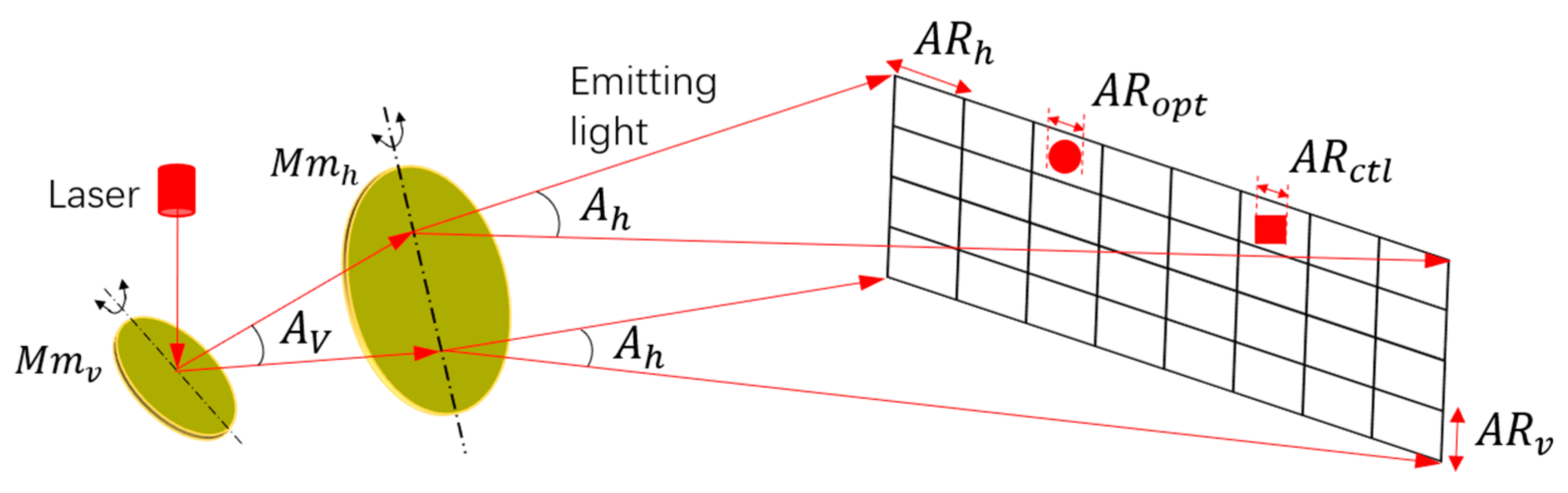
Typically, the angular resolution of a MEMS-based LiDAR system depends on two aspects. One aspect is the control angular resolution of the MEMS mirror (), which is related to the driving [17,18,19] and feedback control [20,21,22] of the MEMS mirror itself. In the current MEMS-based LiDAR system, the is usually controlled under 0.2° in terms of the optical scanning amplitude of the MEMS mirror. The other aspect is the optical resolution (), which mainly depends on the divergence angle of the laser. Due to the millimeter scale of the MEMS mirror, a complicated collimation lens design is generally required to suppress the laser divergence angle [23,24,25]. In order to demonstrate the angular resolution in the separate-axis Lissajous scanning MEMS-based LiDAR system in detail, Figure 1 is depicted below. Here, represents the vertical scanning MEMS mirror, and represents the horizontal scanning MEMS mirror. means the vertical optical scanning angle, and is the horizontal optical scanning angle. In Figure 1, is the horizontal angular resolution, and is the vertical angular resolution. represents the optical angular resolution, and represents the control angular resolution.

Figure 1.
Angular resolution in a separate-axis Lissajous scanning MEMS LiDAR system.
Actually, the and define the upper limit of the angular resolution. The final performance of the angular resolution in a Lissajous scanning MEMS LiDAR system depends on more factors. First of all, the characteristics of the MEMS mirror mainly determine the final angular resolution to display in a Lissajous scanning system, including its vibration frequency, scanning angle, and size. Since the angular resolution can be defined by dividing the scanning angle by the pixel number, Formulas (1) and (2) show the theoretical calculation of the and in the Lissajous scanning MEMS LiDAR system [26,27,28,29,30]. Here, represents the scanning frame rate which is usually above 15Hz for high-speed vehicle navigation to meet the needs of real-time detection [31]. means the vibration frequency of the , is the aperture of the , k is a constant which can be considered as 1.27, and is the laser wavelength. As can be seen, a higher and a larger , , and are simultaneously needed to achieve a higher angular resolution. Thus, the separate-axis Lissajous scanning design provides a reconfigurable approach to obtain a high and flexible angular resolution, as shown in Figure 1.
The second factor is that the laser itself has a duty cycle, which represents the time for the laser to be triggered. Theoretically, as long as Formulas (1) and (2) are satisfied, a fairly high angular resolution can be obtained. However, the laser needs response time to store or release energy, which means the times of the laser emission in one second are restricted. As a result, the angular resolution at a certain frame rate is limited by the laser duty cycle. The following formulas show the relationship between the angular resolution and the laser duty cycle, in which means the number of ranged pixels in one second, represents the laser duty cycle, and means the laser pulse width. Formula (3) shows how to calculate the number of ranged pixels in one second. Formula (4) reveals that cannot exceed the number of laser emissions. Otherwise, the laser could be damaged to some extent. As can be seen, the laser duty cycle also has an impact on the angular resolution. Additionally, a narrower laser pulse width can bring a larger number of laser emissions and then a higher angular resolution.
Another factor is the processing time of the echo signal (), including the acquisition time of echo data and the execution time of the ranging algorithm. In the Lissajous scanning system, the scanning speed at different pixel positions varies with time, and the time interval between the current pixel and the next unrepeatable pixel () is not a constant. To obtain the ranging information of each pixel in real time, the processing time of the echo signal is preferred to be shorter than the minimum . Formula (5) shows the ideal relationship between the angular resolution, , and in this separate-axis Lissajous scanning system. Due to the higher vibration frequency of the vertical scanning MEMS mirror, the minimum is mainly decided by the . As can be seen, a higher angular resolution requires a shorter than . Formula (6) shows this situation regarding the , , and , in which N is the total number of pixels in one frame rate accorded with the angular resolution. is also limited by the , and its maximum value is determined by the greatest common divisor (GCD) of the and . As a result, the processing time of the echo signal influences the angular resolution. In the , the acquisition time of echo data is usually a constant value, which can be obtained by dividing the double detected distance by the velocity of light. The execution time of the ranging algorithm is mainly decided by its complexity, and this time can be optimized. As can be seen, a shorter means that a higher angular resolution at a certain frame rate can be achieved.
As mentioned above, multiple factors influence the real performance of the LiDAR angular resolution. The and define the upper limit of the angular resolution. According to Formula (1) to Formula (6), a high , a large , , and , a narrow , and a short are simultaneously needed to achieve a high angular resolution. Thanks to the independence of the and , a reconfigurable and high angular resolution can be realized in a separate-axis Lissajous scanning MEMS LiDAR system by employing different characteristic uniaxial MEMS mirrors.
3. Design Method and Simulation on Angular Resolution
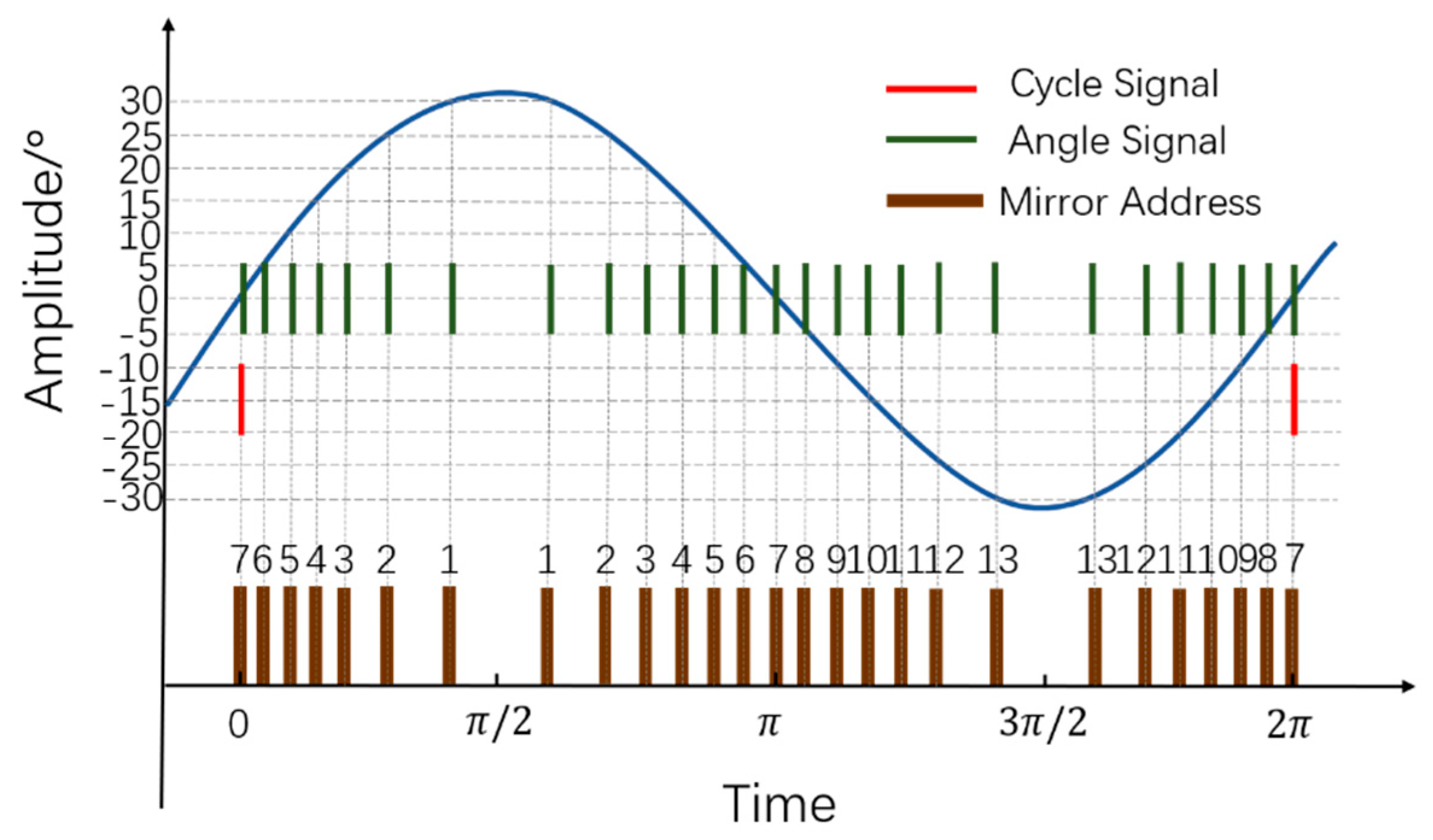
The design method to obtain a reconfigurable angular resolution in a separate-axis Lissajous scanning LiDAR system is presented below. In the MEMS-based LiDAR system, the achievement of the angular resolution depends on the procedure that the laser pulse exactly strikes at the predefined vibration position of the MEMS mirror. Then, it becomes critical to acquire the real-time vibration position of the MEMS mirror and emit the laser pulse accurately. Generally, the MEMS mirror module integrating the driving and feedback control system provides the real-time position information of the MEMS mirror. Figure 2 depicts the situation of the real-time position signals of the uniaxial MEMS mirror. As an example, the angular resolution is 5° and the optical scanning angle is 60° in Figure 2. It should be noted that under a different angular resolution and optical scanning angle, the position signal changes accordingly. As shown, the angle signal, which accords with the angular resolution, represents the real-time angle position of the MEMS mirror. The cycle signal represents the original position in a scanning period of the uniaxial MEMS mirror. In this condition, one scanning cycle of the MEMS mirror starts with the cycle signal, and the angular resolution can be achieved by timely emitting laser pulses to strike on the MEMS mirror with the coming of the angle signals.
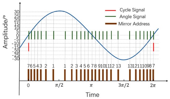
Figure 2.
Position signals of the uniaxial MEMS mirror (angular resolution is 5° and optical scanning angle is 60°).
To achieve 2D scanning, the cycle signal and angle signals of the and the are all needed to confirm the position of each pixel. To obtain an accurate angular resolution, the angle signals of the and the are encoded as the vertical scanning mirror moving address () and the horizontal scanning mirror moving address (), as shown in Figure 2. In this way, the position of each pixel is only defined by the mirror angular address consisting of the and . Additionally, the laser pulse can be triggered at different angular addresses to achieve a reconfigurable angular resolution. It should be noted that the encoded mirror moving address is not continuously in one scanning period of the uniaxial MEMS mirror. Due to the harmonic motion, the same trajectory is scanned twice in one scanning period of the uniaxial MEMS mirror. In this case, the cycle signal represents the 0 degree of the optical scanning angle and thus the exact middle position of the scanning trajectory. Thus, the first angle signal is encoded as address 7 in the condition of a 5° angular resolution and a 60° optical scanning angle. Similarly, when the time is or , the encoded address is address 1 or 13, which represents a 30° optical scanning angle. Then, the vibration position signals of the and the are all encoded as the angular addresses accorded with the angular resolution. A reconfigurable angular resolution can be achieved by emitting laser pulses at the different angular addresses.
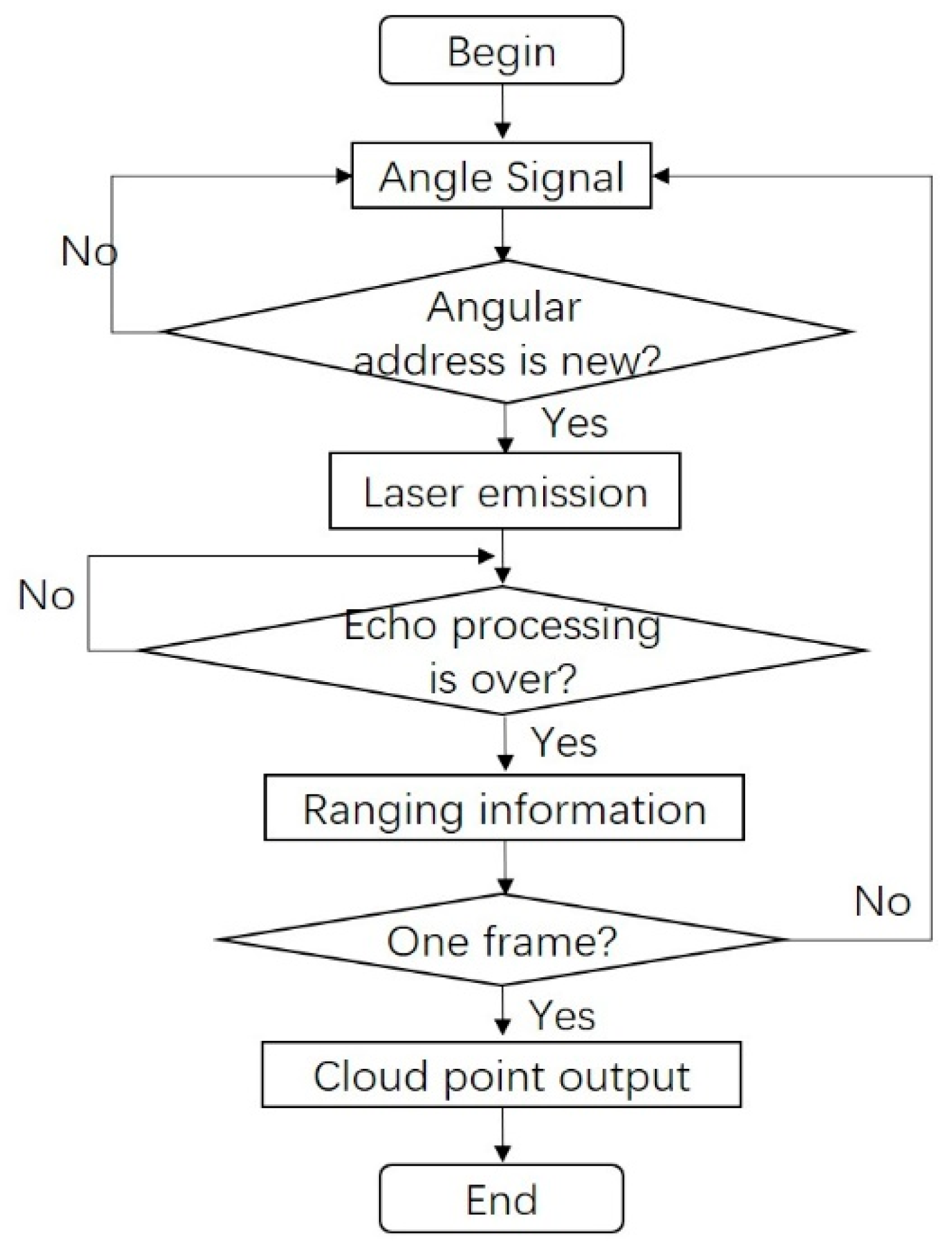
In fact, more aspects need to be considered in the procedure of realizing the reconfigurable angular resolution. At first, due to the scanning form of Lissajous, some pixel positions may be scanned repeatedly in one frame rate. In order to utilize the laser duty cycle effectively, the laser pulse should be prevented from hitting those pixels with the same angular address. Secondly, due to the varying scanning speed of Lissajous scanning at different pixel positions, the processing time of the echo signal should be considered, and the laser pulse should be triggered after the echo processing is over. Based on the above, the entire realization process of the design method on the angular resolution in the separate-axis Lissajous scanning MEMS LiDAR system is depicted in Figure 3. As shown below, the angle signal of the or the can be firstly detected in the ranging procedure. Then, it should be distinguished whether the angular address is repeated or not. If not, the laser pulse can be triggered, and the echo processing unit starts to work. The new angle signal should not be judged until the ranging process is finished. Then, the ranging information of the target can be obtained, including the angular address and detected distance. When all of the unrepeated angular addresses have been detected, the cloud point data of a whole frame can be transmitted to the software to display. Through this design method, reconfigurable angular resolutions can be achieved in the separate-axis Lissajous scanning MEMS LiDAR system.
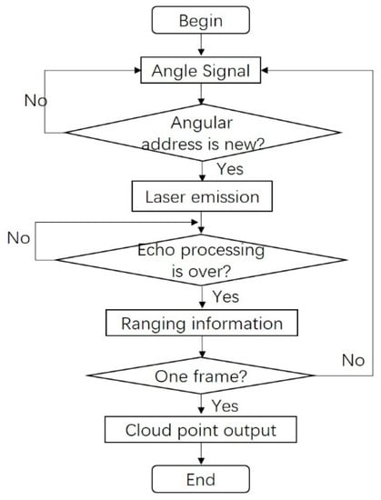
Figure 3.
Procedure of reconfigurable angular resolution design method.
In order to demonstrate the effect of different factors on the angular resolution of the MEMS LiDAR system, a simulation based on the above design method was conducted, as shown below. As mentioned above, the , the , the scanning frequency and angle of the and the , the pulse width and duty cycle of the laser, and the processing time of the echo algorithm all have an impact on the angular resolution. Typically, the , , , , and laser duty cycle are set in advance in a MEMS LiDAR system. In this case, the was assumed to be , the was assumed to be (), was 0.1%, and was . Based on the assumed parameters and the procedure shown in Figure 3, the simulation on the angular resolution was conducted. Table 1 shows the required parameters of the pulse width of the laser, the frequency of the , and the processing time of the echo to achieve different angular resolutions. As can be seen, the high frequency of the vertical scanning MEMS mirror mainly determines the angular resolution of the MEMS LiDAR system. A narrower width of the laser pulse and a shorter echo processing time are also required to achieve a higher angular resolution. It should be noted that this simulation shows the feasibility of the separate-axis Lissajous scanning MEMS LiDAR system to achieve a reconfigurable angular resolution and provides a promising potential to a high-angular-resolution MEMS LiDAR system.

Table 1.
Parameters for different angular resolutions.
4. Experiments
According to the above analysis and simulation on the reconfigurable angular resolution design method, a separate-axis Lissajous scanning MEMS LiDAR system was set up [16], and the experiments were carried out as described below. Two different angular resolutions were demonstrated in the experiments to reveal the feasibility of the reconfigurable angular resolution design method, including 0.2° × 0.62° (horizontal × vertical) and 0.2° × 0.15° (horizontal × vertical).
In the setup of this separate-axis Lissajous scanning MEMS LiDAR system, an OSRAM pulsed laser diode with a peak power of 75 W and a wavelength of 905 nm was employed as the laser emitter, which can emit narrow laser pulses with a relatively high energy. An Analog Devices high-speed analog-to-digital converter (ADC) with a 500 MHz sampling rate was implemented to digitize the echo signal. The high sampling rate of the ADC determines the ranging accuracy. A time of flight (ToF)-based full-waveform echo processing algorithm was operated and accelerated in the Xilinx Field Programmable Gate Array (FPGA). The parallel processing feature of the FPGA can effectively shorten the echo signal processing time. Then, the distance information of the target is obtained after the echo processing. With the cooperation of the FPGA and microcontroller unit (MCU), the point cloud data were finally generated and transferred to display on the software interface. The entire control procedure of the reconfigurable angular resolution design is shown in Figure 3. It should be noted that the uniaxial MEMS mirrors were provided by Zhisensor Technology [32], including the MEMS mirror module named P1223 employed as the and the MEMS mirror module named P1220 employed as the . The MEMS mirror modules also provide the driving and feedback control of the MEMS mirror so that precise control of the MEMS mirror can be achieved [16].
As analyzed above, several factors affect the angular resolution. In this separate-axis Lissajous scanning MEMS LiDAR system, the influence factors are shown below. The is up to 0.05°, which is determined by the high control precision of the MEMS mirror module. With the optical collimation, the design of the laser divergence angle is optimized to 0.2° × 0.15° (horizontal × vertical) so that the is defined as 0.2° × 0.15°. The is 0.1%, which is supported by the laser itself. The optical scanning angle of the is 10°, and the optical scanning angle of the is 60°. The vibration frequency of the is 11,040 Hz, and the vibration frequency of the is 220 Hz. Thanks to the hardware-accelerated processing of the FPGA, the total execution time of the echo processing is controlled in 1.35 us with a maximum detected distance of 20 m. In summary, the specifications of the influence factors of the angular resolution in this separate-axis Lissajous scanning MEMS LiDAR system are illustrated in Table 2.
Table 2.
Influence factors on angular resolution.
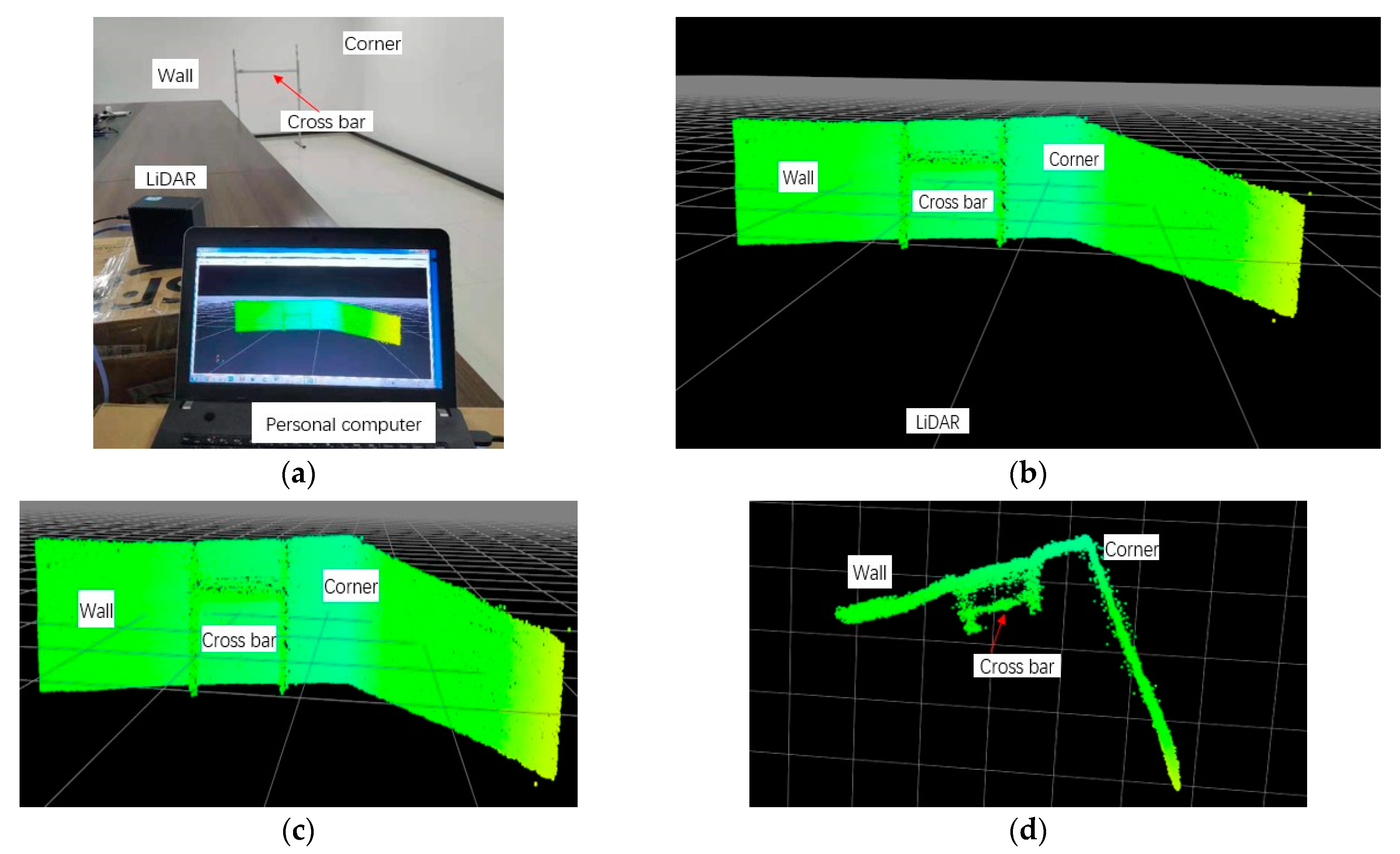
Based on the above parameters provided by the setup of the MEMS LiDAR system, two experiments with different angular resolutions were conducted to demonstrate the feasibility of the reconfigurable design method on the angular resolution in this separate-axis Lissajous scanning MEMS LiDAR system. The entire control procedure of the experiments is shown in Figure 3. Limited by the processing of the hardware circuit, we set up the ranging experiments in a meeting room as shown below. Based on the above analysis, a 0.2° × 0.62° (horizontal × vertical) angular resolution of the separate-axis MEMS LiDAR system with 301 × 17 pixels and a frame rate of 19 Hz was achieved in the first experiment, as shown in Figure 4. In the second experiment, a 0.2° × 0.15° (horizontal × vertical) angular resolution of the separate-axis MEMS LiDAR system with 301 × 65 pixels and a frame rate of 1 Hz was finally obtained, as shown in Figure 5. The above experimental results are consistent with the simulation results in Table 1. As can be seen, two different angular resolutions were obtained in these experiments, which means that a reconfigurable angular resolution can be achieved when MEMS mirrors with different characteristics are employed in the separate-axis MEMS LiDAR system.
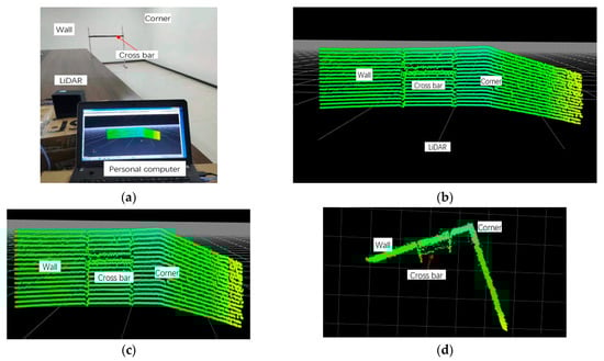
Figure 4.
(a) Picture of the experiment of the angular resolution of 0.2° × 0.62°, (b) panorama of the cloud point, (c) front view, and (d) top view.

Figure 5.
(a) Picture of the experiment of the angular resolution of 0.2° × 0.15°, (b) panorama of the cloud point, (c) front view, and (d) top view.
In the ranging image of the experiments, a bracket, the background wall, and the corner were ranged as the targets, in which the bracket was placed at approximately 6 m in front of the MEMES LiDAR system, and the background wall was situated at approximately 7 m. It should be noted that the 0.2° horizontal angular resolution has been proven in our earlier study [16]. In experiment 1, the bracket with a 6 cm-wide crossbar was placed in front of the MEMS LiDAR system, and the 0.62° vertical angular resolution with 17 pixels can be seen from the cloud point image, as shown in Figure 4. In experiment 2, the bracket with a 2 cm-wide crossbar was placed in front of the MEMS LiDAR system, and Figure 5 shows the 0.15° vertical angular resolution with 65 pixels in the ranging experiment. However, due to the limitation of the design and processing ability of the hardware circuit, the cloud point noise appears on the object boundary. Nonetheless, these experiments provide support for the reconfigurable design method on the angular resolution in this separate-axis Lissajous scanning MEMS LIDAR system. In our next work, we will focus on improving this design to provide much better 3D ranging images.
5. Conclusions
In this paper, we propose a reconfigurable angular resolution design method in a separate-axis Lissajous scanning MEMS LiDAR system. This design method reveals the procedure of achieving different angular resolutions in a Lissajous scanning MEMS LiDAR system and demonstrates the influence of different factors on the angular resolution, including the characteristics of the MEMS mirrors, the laser duty cycle, the laser pulse width, the processing time of the echo, the control precision of the MEMS mirror, and the laser divergence angle. The simulation showed which conditions are required to obtain a high angular resolution, and experiments with different angular resolutions were conducted. The experiment results show the feasibility of the reconfigurable angular resolution design method in a separate-axis Lissajous scanning MEMS LiDAR system. Based on this design method, the separate-axis Lissajous scanning MEMS LiDAR system can employ larger-amplitude, higher-frequency MEMS mirrors to obtain a higher angular resolution. In our next study, more improvements of this design will be researched to provide a promising solution to high-angular-resolution MEMS LiDAR.
Author Contributions
Conceptualization, F.X., D.Q. and C.X.; methodology, F.X., Y.H., X.S., W.Z. and Q.F.; software, F.X. and Y.H.; writing—original draft preparation, F.X.; writing—review and editing, D.Q. and C.X. All authors have read and agreed to the published version of the manuscript.
Funding
This research was funded by the National Natural Science Foundation of China (Grant No. U21B2035, 62074128).
Acknowledgments
Thanks to Lingzhi Wei and Long Liu for their help in the experiments.
Conflicts of Interest
The authors declare no conflict of interest.
References
- Müller, D.; Ansmann, A.; Mattis, I.; Tesche, M.; Wandinger, U.; Althausen, D.; Pisani, G. Aerosol-type-dependent lidar ratios observed with raman lidar. J. Geophys. Res. 2007, 112, D16202. [Google Scholar] [CrossRef]
- Akai, N.; Morales, L.Y.; Yamaguchi, T.; Takeuchi, E.; Ninomiya, Y. Autonomous driving based on accurate localization using multilayer lidar and dead reckoning. In Proceedings of the IEEE 20th International Conference on Intelligent Transportation Systems, Yokohama, Japan, 16–19 October 2017. [Google Scholar]
- Wang, H.; Wang, B.; Liu, B.; Meng, X.; Yang, G. Pedestrian recognition and tracking using 3d lidar for autonomous vehicle. Robotics Auton. Syst. 2017, 88, 71–78. [Google Scholar] [CrossRef]
- Sprunk, C.; Tipaldi, G.D.; Cherubini, A.; Burgard, W. Lidar-based teach-and-repeat of mobile robot trajectories. In Proceedings of the IROS 2013—IEEE/RSJ International Conference on Intelligent Robots and Systems, Tokyo, Japan, 7 November 2013. [Google Scholar]
- Lee, S.J.; Lim, J.; Moon, S.; Lee, J.; Lee, J.H. Mems scanner-based biaxial lidar system for direct detection of three-dimensional images. In Proceedings of the 2018 International Conference on Optical MEMS and Nanophotonics (OMN), Lausanne, Switzerland, 29 July–2 August 2018. [Google Scholar]
- Halterman, R.; Bruch, M. Velodyne hdl-64e lidar for unmanned surface vehicle obstacle detection. In Proceedings of the SPIE Defense, Security, and Sensing, Orlando, FL, USA, 5–9 April 2010; Volume 7692, p. 9. [Google Scholar]
- Moss, R.; Ping, Y.; Bai, X.; Quesada, E.; Lawler, W.B. Low-cost compact mems scanning ladar system for robotic applications. In Proceedings of the Laser Radar Technology and Applications XVII, Proceedings of the SPIE Defense, Security, and Sensing, Baltimore, MD, USA, 24–26 April 2012; SPIE: Bellingham, WA, USA, 2012; p. 2. [Google Scholar]
- Niclass, C.; Ito, K.; Soga, M.; Matsubara, H.; Kagami, M. Design and characterization of a 256x64-pixel single- photon imager in cmos for a mems-based laser scanning time-of-flight sensor. Opt. Express 2012, 20, 11863–11881. [Google Scholar] [CrossRef] [PubMed]
- Wu, K.; Zhang, H.; Chen, Y.; Luo, Q.; Xu, K. All-silicon microdisplay using efficient hot-carrier electroluminescence in standard 0.18μm cmos technology. IEEE Electron Device Lett. 2021, 99, 1. [Google Scholar] [CrossRef]
- Kimoto, K.; Asa, N.; Mori, T.; Hara, Y.; Yuta, S. Development of small size 3d lidar. In Proceedings of the IEEE International Conference on Robotics & Automation, Hongkong, China, 31 May–5 June 2014. [Google Scholar]
- Choudhury, P.K.; Lee, C.H. Simultaneous enhancement of scanning area and imaging speed for a mems mirror based high resolution lidar. IEEE Access 2020, 8, 1. [Google Scholar] [CrossRef]
- Holmstrom, S.T.S.; Baran, U.; Urey, H. Mems laser scanners: A review. Microelectromechanical Syst. 2014, 23, 259–275. [Google Scholar] [CrossRef]
- Urey, H.; Kan, C.; Davis, W.O. Vibration mode frequency formulae for micromechanical scanners. J. Micromechanics Microengineering 2005, 15, 1713–1721. [Google Scholar] [CrossRef]
- Gu-Stoppel, S.; Janes, J.; Quenzer, H.J.; Eisermann, C.; Benecke, W. High frequency 1d piezoelectric resonant microscanners with large displacements. Procedia Eng. 2014, 87, 1593–1596. [Google Scholar] [CrossRef]
- Schwarz, F.; Senger, F.; Albers, J.; Malaurie, P.; Hofmann, U. Resonant 1d mems mirror with a total optical scan angle of 180ř for automotive lidar. In MOEMS and Miniaturized Systems XIX; SPIE—International Society for Optics and Photonics: Bellingham, WA, USA, 2020. [Google Scholar]
- Xu, F.; Qiao, D.; Song, X.; Zheng, W.; Fan, Q. A semi-coaxial mems lidar design with independently adjustable detection range and angular resolution. Sens. Actuators A Phys. 2021, 326, 112715. [Google Scholar] [CrossRef]
- Xu, F.; Qiao, D.; Song, X.; Zheng, W.; Fan, Q. A semi-coaxial mems-based lidar. In Proceedings of the IECON 2019—45th Annual Conference of the IEEE Industrial Electronics Society, Lisbon, Portugal, 14–17 October 2019. [Google Scholar]
- Lemaire, M.; Barras, T.; Abele, N. Method for Controlling the Position of a Mems Mirror. U.S. Patent 20160231557A1, 2017. Available online: https://patents.google.com/patent/US20160231557A1/en (accessed on 30 January 2022).
- Maruyama, S.; Machida, K.; Toshiyoshi, H.; Konishi, T.; Fujita, H. An interface circuit for time-multiplexed electrostatic drive and sample of electrostatic mems mirror. In Proceedings of the 2015 Symposium on Design, Test, Integration and Packaging of MEMS/MOEMS (DTIP), Montpellier, France, 27–30 April 2015. [Google Scholar]
- Tortschanoff, A.; Frank, A.; Wildenhain, M.; Sandner, T.; Schenk, H.; Kenda, A. Position feedback and phase control of resonant moems-mirrors with one and two axes. Procedia Eng. 2010, 5, 689–692. [Google Scholar] [CrossRef]
- Cagdaser, B.; Jog, A.; Last, M.; Leibowitz, B.S.; Boser, B.E. Capacitive Sense Feedback Control for Mems Beam Steering Mirrors. 2004. Available online: https://transducer-research-foundation.org/technical_digests/HiltonHead_2004/hh2004_0348.pdf (accessed on 30 January 2022).
- Milanovi, V.; Kasturi, A.; Yang, J.; Hu, F. Closed-loop control of gimbal-less mems mirrors for increased bandwidth in lidar applications. In Laser Radar Technology & Applications XXII; SPIE—International Society for Optics and Photonics: Bellingham, WA, USA, 2017. [Google Scholar]
- Xu, K. Silicon electro-optic micro-modulator fabricated in standard cmos technology as components for all silicon monolithic integrated optoelectronic systems. J. Micromechanics Microengineering 2021, 31, 054001. [Google Scholar] [CrossRef]
- Lee, X.; Wang, C. Optical design for uniform scanning in mems-based 3d imaging lidar. Appl. Opt. 2015, 54, 2219–2223. [Google Scholar] [CrossRef] [PubMed]
- Xiaobao, L.; Wang, C.; Luo, Z.; Li, S. Optical design of a new folding scanning system in mems-based lidar. Opt. Laser Technol. 2019, 125, 106013. [Google Scholar]
- Hung, A.; Lai, H.; Lin, T.; Fu, S.; Lu, M. An electrostatically-driven 2D micro-scanning mirror with capacitive sensing for projection display. Sens. Actuators A Phys. 2014, 222, 122–129. [Google Scholar] [CrossRef]
- Scholles, M.; Braeuer, A.; Frommhagen, K.; Gerwig, C.; Schwarzenberg, M. Ultra compact laser projection systems based on two-dimensional resonant micro scanning mirrors—Art. no. 64660a. In Proceedings of the MOEMS-MEMS 2007 Micro and Nanofabrication, San Jose, CA, USA, 22 January 2007; SPIE: Bellingham, WA, USA, 2007; Volume 6466. [Google Scholar]
- Wang, J.; Zhang, G.; You, Z. Design rules for dense and rapid lissajous scanning. Microsyst. Nanoeng. 2020, 6, 101. [Google Scholar] [CrossRef] [PubMed]
- Teo, Y.R.; Yong, Y.K.; Fleming, A.J. A review of scanning methods and control implications for scanning probe microscopy. In Proceedings of the 2016 American Control Conference (ACC), Boston, MA, USA, 6–8 July 2016. [Google Scholar]
- Urey, H. Torsional mems scanner design for high-resolution scanning display systems. In Proceedings of the International Symposium on Optical Science and Technology, Seattle, WA, USA, 4 June 2002; SPIE: Bellingham, WA, USA, 2002; Volume 4773, pp. 27–37. [Google Scholar]
- Schwarz, B. Lidar: Mapping the world in 3D. Nat. Photonics 2010, 4, 429–430. [Google Scholar] [CrossRef]
- Web of the Mems Mirrors. Available online: http://www.en.zhisensor.com/?page_id=15624 (accessed on 30 January 2022).

Publisher’s Note: MDPI stays neutral with regard to jurisdictional claims in published maps and institutional affiliations. |
© 2022 by the authors. Licensee MDPI, Basel, Switzerland. This article is an open access article distributed under the terms and conditions of the Creative Commons Attribution (CC BY) license (https://creativecommons.org/licenses/by/4.0/).