
High Sensitivity Strain Sensors Using Four-Core Fibers through a Corner-Core Excitation


Abstract
:1. Introduction
2. Fabrications, Experimental Set-Up, and Working Principle
3. Results and Discussion
4. Conclusions
Author Contributions
Funding
Data Availability Statement
Acknowledgments
Conflicts of Interest
References
- Zeng, H.; Geng, T.; Yang, W.; An, M.; Li, J.; Yang, F.; Yuan, L. Combining Two Types of Gratings for Simultaneous Strain and Temperature Measurement. IEEE Photon- Technol. Lett. 2016, 28, 477–480. [Google Scholar] [CrossRef]
- Sun, M.; Xu, B.; Dong, X.; Li, Y. Optical fiber strain and temperature sensor based on an in-line Mach–Zehnder interferometer using thin-core fiber. Opt. Commun. 2012, 285, 3721–3725. [Google Scholar] [CrossRef]
- Zhao, Y.; Chen, M.-Q.; Lv, R.-Q.; Xia, F. In-fiber rectangular air fabry-perot strain sensor based on high-precision fiber cutting platform. Opt. Commun. 2017, 384, 107–110. [Google Scholar] [CrossRef]
- Hatta, A.M.; Semenova, Y.; Wu, Q.; Farrell, G. Strain sensor based on a pair of single-mode-multimode-single-mode fiber structures in a ratiometric power measurement scheme. Appl. Opt. 2010, 49, 536–541. [Google Scholar] [CrossRef] [PubMed]
- Xia, C.; Bai, N.; Ozdur, I.; Zhou, X.; Li, G. Supermodes for optical transmission. Opt. Express 2011, 19, 16653–16664. [Google Scholar] [CrossRef]
- Villatoro, J.; Arrizabalaga, O.; Antonio-Lopez, E.; Zubia, J.; Ocariz, R.S. Multicore Fiber Sensors; OFC: Los Angeles, CA, USA, 2017; Available online: https://ieeexplore.ieee.org/xpl/conhome/7932337/proceeding (accessed on 9 January 2022).
- Salceda-Delgado, G.; Van Newkirk, A.; Antonio-Lopez, J.E.; Martinez-Rios, A.; Schülzgen, A.; Correa, R.A. Compact fiber-optic curvature sensor based on super-mode interference in a seven-core fiber. Opt. Lett. 2015, 40, 1468–1471. [Google Scholar] [CrossRef]
- Jiang, Y.; Wang, T.; Liu, C.; Feng, D.; Jiang, B.; Yang, D.; Zhao, J. Simultaneous measurement of refractive index and temperature with high sensitivity based on a multipath fiber Mach–Zehnder interferometer. Appl. Opt. 2019, 58, 4085–4090. [Google Scholar] [CrossRef]
- Xia, C.; Eftekhar, M.A.; Correa, R.A.; Antonio-Lopez, J.E.; Schulzgen, A.; Christodoulides, D.; Li, G. Supermodes in Coupled Multi-Core Waveguide Structures. IEEE J. Sel. Top. Quantum Electron. 2016, 22, 196–207. [Google Scholar] [CrossRef]
- Van Newkirk, A.; Antonio-Lopez, J.E.; Salceda-Delgado, G.; Piracha, M.U.; Correa, R.A.; Schülzgen, A.; Antonio-Lopez, E. Multicore Fiber Sensors for Simultaneous Measurement of Force and Temperature. IEEE Photon. Technol. Lett. 2015, 27, 1523–1526. [Google Scholar] [CrossRef]
- Floris, I.; Sales, S.; Calderón, P.A.; Adam, J.M. Measurement uncertainty of multicore optical fiber sensors used to sense curvature and bending direction. Measurement 2018, 132, 35–46. [Google Scholar] [CrossRef]
- Leung, C.K.Y.; Wan, K.T.; Inaudi, D.; Bao, X.; Habel, W.; Zhou, Z.; Ou, J.; Ghandehari, M.; Wu, H.C.; Imai, M. Review: Optical fiber sensors for civil engineering applications. Mater. Struct. 2015, 48, 871–906. [Google Scholar] [CrossRef] [Green Version]
- Barrera, D.; Finazzi, V.; Villatoro, J.; Sales, S.; Pruneri, V. Packaged Optical Sensors Based on Regenerated Fiber Bragg Gratings for High Temperature Applications. IEEE Sensors J. 2011, 12, 107–112. [Google Scholar] [CrossRef]
- Yadav, T.K.; Narayanaswamy, R.; Abu Bakar, M.H.; Kamil, Y.M.; Mahdi, M.A. Single mode tapered fiber-optic interferometer based refractive index sensor and its application to protein sensing. Opt. Express 2014, 22, 22802–22807. [Google Scholar] [CrossRef] [PubMed]
- Liehr, S.; Lenke, P.; Wendt, M.; Krebber, K.; Seeger, M.; Thiele, E.; Metschies, H.; Gebreselassie, B.; Munich, J.C. Polymer Optical Fiber Sensors for Distributed Strain Measurement and Application in Structural Health Monitoring. IEEE Sens. J. 2009, 9, 1330–1338. [Google Scholar] [CrossRef]
- Tsiminis, G.; Klarić, T.; Schartner, E.P.; Warren-Smith, S.C.; Lewis, M.D.; Koblar, S.A.; Monro, T.M. Generating and measuring photochemical changes inside the brain using optical fibers: Exploring stroke. Biomed. Opt. Express 2014, 5, 3975–3980. [Google Scholar] [CrossRef] [Green Version]
- Sakamoto, T.; Mori, T.; Wada, M.; Yamamoto, T.; Matsui, T.; Nakajima, K.; Yamamoto, F. Experimental and numerical evaluation of inter-core differential mode delay characteristic of weakly-coupled multi-core fiber. Opt. Express 2014, 22, 31966–31976. [Google Scholar] [CrossRef] [PubMed]
- Youn, J.H.; Song, K.Y.; Park, H.S. Dynamic In-Line Routing Between Distant Cores of a Multi-Core Fiber. J. Light. Technol. 2020, 38, 6076–6081. [Google Scholar] [CrossRef]
- Richardson, D.J.; Fini, J.M.; Nelson, L.E. Space-division multiplexing in optical fibres. Nat. Photon. 2013, 7, 354–362. [Google Scholar] [CrossRef] [Green Version]
- Gasulla, I.; Capmany, J. Microwave Photonics Applications of Multicore Fibers. IEEE Photon. J. 2012, 4, 877–888. [Google Scholar] [CrossRef]
- Zhang, L.; Tian, Z.; Chen, N.-K.; Han, H.; Liu, C.-N.; Grattan, K.; Rahman, B.M.A.; Zhou, H.; Liaw, S.-K.; Bai, C. Room-Temperature Power-Stabilized Narrow-Linewidth Tunable Erbium-Doped Fiber Ring Laser Based on Cascaded Mach-Zehnder Interferometers With Different Free Spectral Range for Strain Sensing. J. Light. Technol. 2019, 38, 1966–1974. [Google Scholar] [CrossRef]
- Hayashi, T.; Tamura, Y.; Hasegawa, T.; Taru, T. Record-Low Spatial Mode Dispersion and Ultra-Low Loss Coupled Multi-Core Fiber for Ultra-Long-Haul Transmission. J. Light. Technol. 2016, 35, 450–457. [Google Scholar] [CrossRef]
- Diamantopoulos, N.-P.; Shikama, K.; Nishi, H.; Fujii, T.; Kishi, T.; Takeda, K.; Abe, Y.; Matsui, T.; Kakitsuka, T.; Fukuda, H.; et al. 400-Gb/s DMT-SDM Transmission Based on Membrane DML-Array-on-Silicon. J. Light. Technol. 2018, 37, 1805–1812. [Google Scholar] [CrossRef]
- Shirakawa, A.; Chen, M.; Suzuki, Y.; Sato, K.; Fan, X.; Tünnermann, H.; Karow, M.; Olausson, C.B.; Petersen, S.R.; Alkeskjold, T.T. Photonic bandgap fiber lasers and multicore fiber lasers for next generation high power lasers. In Advanced Photonics; Optica Publishing Group: Cluj Napoca, Romania, 2014; SoTu4B.2. [Google Scholar] [CrossRef]
- Michaille, L.; Bennett, C.R.; Taylor, D.M.; Shepherd, T.J. Multicore Photonic Crystal Fiber Lasers for High Power/Energy Applications. IEEE J. Sel. Top. Quantum Electron. 2009, 15, 328–336. [Google Scholar] [CrossRef]
- Prudenzano, F.; Mescia, L.; Di Tommaso, A.; Surico, M.; De Sario, M. Design and refinement of rare earth doped multicore fiber lasers. Opt. Mater. 2013, 35, 1941–1946. [Google Scholar] [CrossRef]
- Chen, N.-K.; Yang, T.-H.; Chen, Y.-N.; Guo, T.; Guan, B.-O. High sensitivity stretched-abrupt-tapered Mach-Zehnder interferometer with optical attractive force for active microsensing applications. Appl. Phys. Lett. 2013, 102, 171101. [Google Scholar] [CrossRef]
- Yan, D.; Tian, Z.; Chen, N.-K.; Zhang, L.; Yao, Y.; Xie, Y.; Shum, P.P.; Grattan, K.T.V.; Wang, D. Observation of split evanescent field distributions in tapered multicore fibers for multiline nanoparticle trapping and microsensing. Opt. Express 2021, 29, 9532–9543. [Google Scholar] [CrossRef]
- Tagoudi, E.; Milenko, K.; Pissadakis, S. Intercore Coupling Effects in Multicore Optical Fiber Tapers Using Magnetic Fluid Out-Claddings. J. Light. Technol. 2016, 34, 5561–5565. [Google Scholar] [CrossRef]
- Zhang, C.; Ning, T.; Li, J.; Pei, L.; Li, C.; Lin, H. Refractive index sensor based on tapered multicore fiber. Opt. Fiber Technol. 2016, 33, 71–76. [Google Scholar] [CrossRef]
- Suo, L.; Zhou, H.; Peng, Y.-P.; Yang, F.; Chui, H.-C.; Chen, N.-K. High Sensitivity Fiber Refractive Index Sensors Based on Asymmetric Supermodes Interference in Tapered Four Core Fiber. Photonics 2022, 9, 45. [Google Scholar] [CrossRef]
- Barrera, D.; Gasulla, I.; Sales, S. Multipoint Two-Dimensional Curvature Optical Fiber Sensor Based on a Nontwisted Homogeneous Four-Core Fiber. J. Light. Technol. 2014, 33, 2445–2450. [Google Scholar] [CrossRef]
- Askins, C.G.; Miller, G.A.; Friebele, E.J. Bend and Twist Sensing in a Multiple-Core Optical Fiber. In Proceedings of the 2008 Conference on Optical Fiber Communication/National Fiber Optic Engineers Conference (OFC/NFOEC), San Diego, CA, USA, 24–28 February 2008; pp. 1–3. [Google Scholar] [CrossRef]
- Li, C.; Ning, T.; Zhang, C.; Li, J.; Zhang, C.; Wen, X.; Lin, H.; Pei, L. All-fiber multipath Mach-Zehnder interferometer based on a four-core fiber for sensing applications. Sensors Actuators A: Phys. 2016, 248, 148–154. [Google Scholar] [CrossRef]
- Shao, Z.; Qiao, X.; Rong, Q. Compact gas refractometer based on a tapered four-core fiber. Appl. Opt. 2018, 57, 10198–10206. [Google Scholar] [CrossRef] [PubMed]
- Bao, W.; Sahoo, N.; Sun, Z.; Wang, C.; Liu, S.; Wang, Y.; Zhang, L. Selective fiber Bragg grating inscription in four-core fiber for two-dimension vector bending sensing. Opt. Express 2020, 28, 26461–26469. [Google Scholar] [CrossRef] [PubMed]
- Liu, Y.; Zhou, A.; Yuan, L. Sensitivity-enhanced humidity sensor based on helix structure-assisted Mach-Zehnder interference. Opt. Express 2019, 27, 35609–35620. [Google Scholar] [CrossRef] [PubMed]
- Liao, C.R.; Wang, D.N.; Wang, Y. Microfiber in-line Mach–Zehnder interferometer for strain sensing. Opt. Lett. 2013, 38, 757–759. [Google Scholar] [CrossRef] [PubMed]
- Bai, X.; Fan, D.; Wang, S.; Pu, S.; Zeng, X. Strain Sensor Based on Fiber Ring Cavity Laser with Photonic Crystal Fiber In-Line Mach–Zehnder Interferometer. IEEE Photon- J. 2014, 6, 1–8. [Google Scholar] [CrossRef]
- Tian, K.; Farrell, G.; Wang, X.; Yang, W.; Xin, Y.; Liang, H.; Lewis, E.; Wang, P. Strain sensor based on gourd-shaped single-mode-multimode-single-mode hybrid optical fibre structure. Opt. Express 2017, 25, 18885–18896. [Google Scholar] [CrossRef] [Green Version]
- Chen, H.F.; Wang, D.N.; Hong, W. Slightly Tapered Optical Fiber with Inner Air-Cavity as a Miniature and Versatile Sensing Device. J. Light. Technol. 2015, 33, 62–68. [Google Scholar] [CrossRef]
- Oliveira, R.; Bilro, L.; Marques, T.H.R.; Cordeiro, C.M.B.; Nogueira, R. Strain Sensitivity Enhancement of a Sensing Head Based on ZEONEX Polymer FBG in Series with Silica Fiber. J. Light. Technol. 2018, 36, 5106–5112. [Google Scholar] [CrossRef]


| Reference No. | This Work | [34] | [38] | [39] | [40] | [41] | [42] |
|---|---|---|---|---|---|---|---|
| Sensor scheme | TFCFs | FCFs | HCFs | PCFs | MMFs | Inner air-cavity | FBGs |
| Dynamic range | 0–60 με | 0–2000 με | 0–1000 με | 0–2100 με | 0–1000 με | 0–2000 με | 0–300 με |
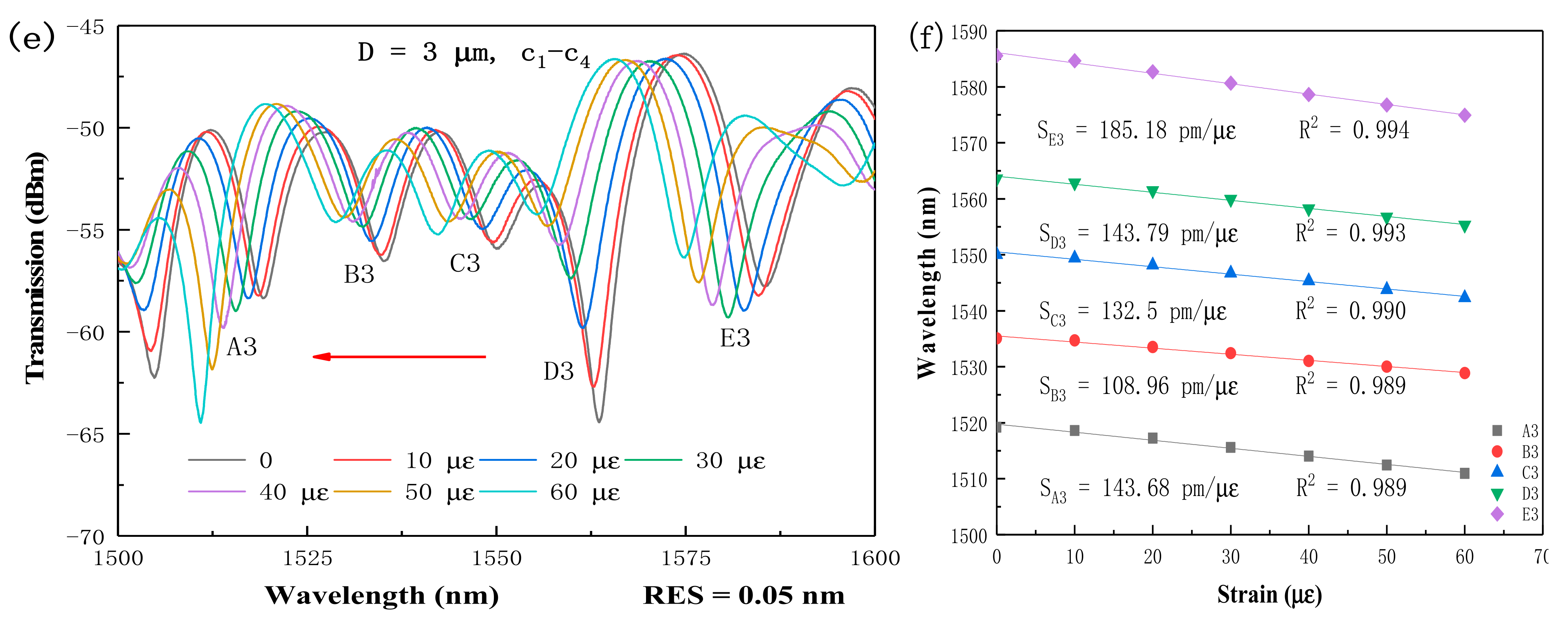
| Maximum sensitivity | 185.18 pm/μԑ | 1.78 pm/με | 6.80 pm/με | 2.10 pm/με | 2.6 pm/με | 22.5 pm/με | 39.791 pm/με |
Publisher’s Note: MDPI stays neutral with regard to jurisdictional claims in published maps and institutional affiliations. |
© 2022 by the authors. Licensee MDPI, Basel, Switzerland. This article is an open access article distributed under the terms and conditions of the Creative Commons Attribution (CC BY) license (https://creativecommons.org/licenses/by/4.0/).
Share and Cite
Suo, L.; Peng, Y.-P.; Yao, C.-K.; Ren, S.; Lu, X.; Chen, N.-K. High Sensitivity Strain Sensors Using Four-Core Fibers through a Corner-Core Excitation. Micromachines 2022, 13, 431. https://doi.org/10.3390/mi13030431
Suo L, Peng Y-P, Yao C-K, Ren S, Lu X, Chen N-K. High Sensitivity Strain Sensors Using Four-Core Fibers through a Corner-Core Excitation. Micromachines. 2022; 13(3):431. https://doi.org/10.3390/mi13030431
Chicago/Turabian StyleSuo, Lina, Ya-Pei Peng, Cheng-Kai Yao, Shijie Ren, Xinhe Lu, and Nan-Kuang Chen. 2022. "High Sensitivity Strain Sensors Using Four-Core Fibers through a Corner-Core Excitation" Micromachines 13, no. 3: 431. https://doi.org/10.3390/mi13030431
APA StyleSuo, L., Peng, Y.-P., Yao, C.-K., Ren, S., Lu, X., & Chen, N.-K. (2022). High Sensitivity Strain Sensors Using Four-Core Fibers through a Corner-Core Excitation. Micromachines, 13(3), 431. https://doi.org/10.3390/mi13030431