Article

Optimized Super-Wideband MIMO Antenna with High Isolation for IoT Applications

School of Computer Science and Engineering, Central South University, Changsha 410083, China
*
Author to whom correspondence should be addressed.
Micromachines 2022, 13(4), 514; https://doi.org/10.3390/mi13040514
Submission received: 30 November 2021 / Revised: 21 March 2022 / Accepted: 21 March 2022 / Published: 25 March 2022
(This article belongs to the Special Issue Miniaturized Microwave Components and Devices)

Abstract

:
A compact, low profile, multiple-input–multiple-output (MIMO) diversity antenna with super-wideband (SWB) characteristics has been proposed. The proposed antenna comprises four symmetric monopole-radiating elements printed on low-cost FR4 substrate with the slotted ground plane. The single antenna of a monopole structure and a quad-port MIMO antenna, with the dimensions of 30 × 20 mm2 and 60 × 55 mm2, respectively, are ideal for IoT and high-speed data applications. The proposed MIMO antenna has a high diversity gain and low envelope correlation coefficient (ECC) within the frequency range. Simulated results demonstrate the performance of the MIMO-SWB antenna, which operates from 2.3 to 23 GHz, with a high isolation level over 20 dB in the achieved frequency band. Moreover, the proposed MIMO antenna has been investigated with mirror fashion and orthogonal structure. Both structures provide similar results except for mutual coupling performance. The orthogonal adjustment for high isolation achieves better results with the proposed model. Further, the prototype of the proposed antenna is fabricated and measured effectively. Simulated and measured results show good agreement for super-wideband applications.

1. Introduction

To achieve a higher data rate and reliable services, super wideband is the most preferred technology for today’s wireless communication. It has promising applications in short-range transmission, indoor, and medical applications. By expanding bandwidth, we can leverage marge wireless technologies in one device for more better product [1]. Ultra-wideband (UWB) operating band is from 3.1 to 10.6 GHz for wireless applications [2]. For SWB, there is no predefined frequency spectrum, such as UWB. Comparison in terms of the wideband antenna is to perform in terms of bandwidth ratio, which should be at least 10:1. MIMO was introduced to improve multiplexing gain and diversity to improve link quality [3]. To control multipath fading, we need to place multiple antenna elements in a limited area, which causes distraction because of mutual coupling [4]. To control mutual coupling, many techniques were explored in the literature. So far, many designs and methods have been introduced by researchers for expanding bandwidth and enhancement of MIMO technology for system stability. However, the problem of super wideband with high isolation in the complete spectrum within a compact structure is still serious.
SWB-MIMO antenna performance depends on the design structure. MIMO antenna has many design challenges to achieve wide bandwidth, high isolation, radiation pattern, stable gain, and size reduction. To overcome these challenges, MIMO antenna is examined by many researchers, and a variety of techniques are adopted, such as defected ground structure, metamaterial, feeding structure, neutralization line, isolation based on pin diode, and parasitic element approach. Defected ground disturbs the surface current, as a result, reduces mutual coupling among antenna elements [5]. The neutralization line approach is used to solve the problem of antenna matching and improves the isolation between antenna elements [6,7]. The etching Slot technique controls the current on-ground plane by suppressing the coupling between the closely spaced antennas and acts similar to a band-stop filter [8]. Similarly, for negative permittivity/permeability effects, metamaterial structures can be placed in radiation patch, ground, or between the antenna elements [9].
The concept of MIMO technology combined with SWB is an exciting research topic for enhancing today’s wireless communication system [10,11,12]. For example, 5G super-high bit rate transmission supports simultaneous operation of low-power sensors and high-definition video streaming. In [13,14,15,16], simple SWB antennas in the planar and coplanar domains were presented from the literature. In [17], the author presented a SWB-MIMO antenna with size reduction technique by an appropriate alteration in the feedline using a multistage numerical optimization method. Furthermore, in [18,19,20], all authors proposed MIMO antennas with good mutual coupling and suitable diversity gain. However, some of these antennas are miniaturized in size but compromised on expanding bandwidth from UWB range or minimum antenna isolation and correlation coefficient in the whole frequency band. In [21,22,23,24,25,26,27], the SWB-MIMO technique was implemented in the planar and coplanar domain. The parasitic structure was used to reduce mutual coupling in the monopole planar structures [28,29]. Although these MIMO antennas achieved super wideband and high isolation, they are still large for high data-rate transmission applications. Despite these designs, we still need a low-profile, compact SWB-MIMO antenna for high-data-rate applications. In IoT applications, advance wireless technologies are merging to introduce new features in one device [30,31].
Hence, the research intends to design low-profile planar SWB-MIMO antennas with good performance of isolation, gain, ECC, and efficiency. The proposed structure can perform as single, two-port, and four-port antenna on the same operating frequency range from 2.3 to 23 GHz. Furthermore, the orthogonal adjustment is used to improve isolation. The proposed antenna model with its performance and characteristics is discussed in the following section.

2. Antenna Design and Methodology

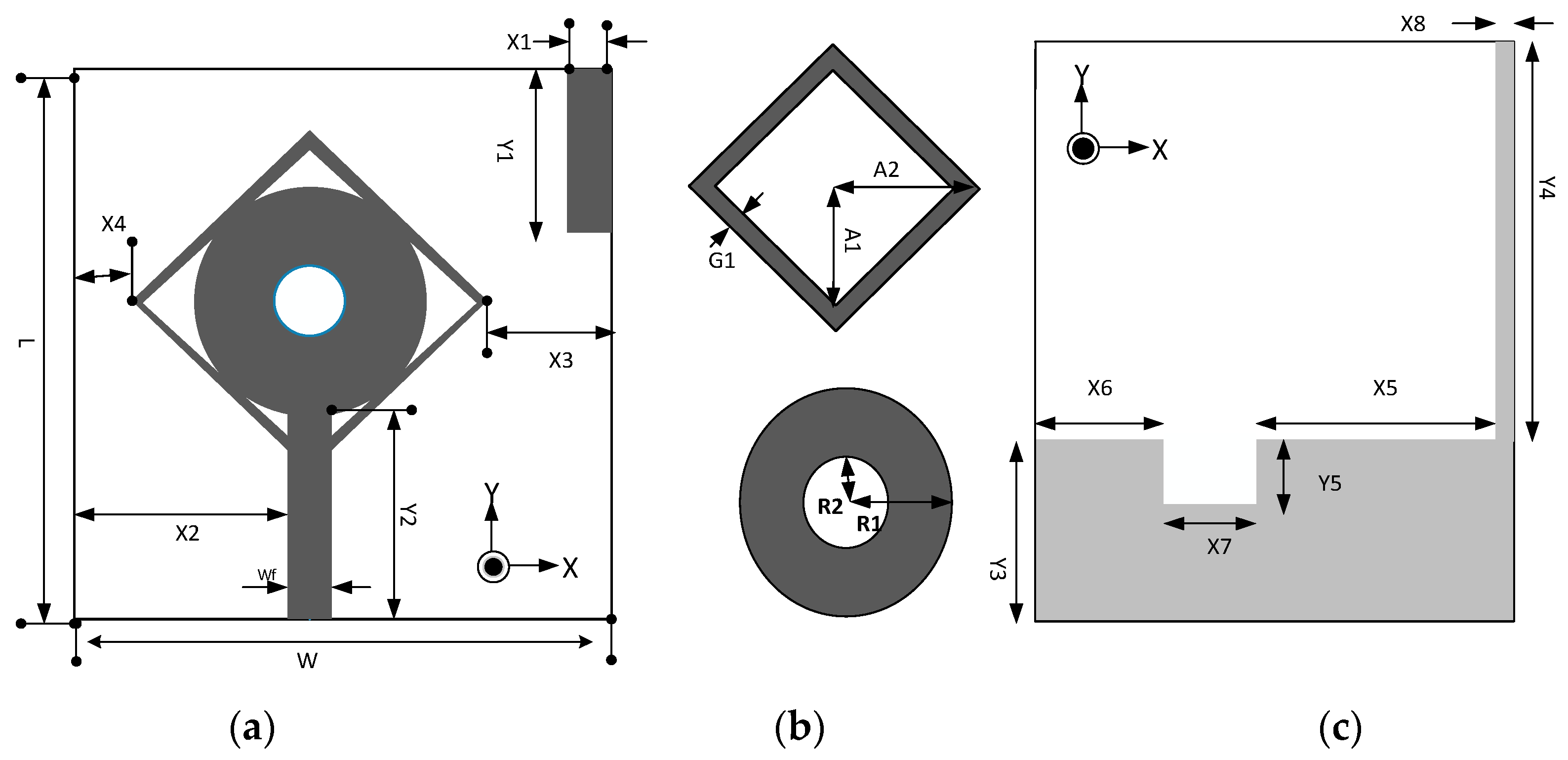
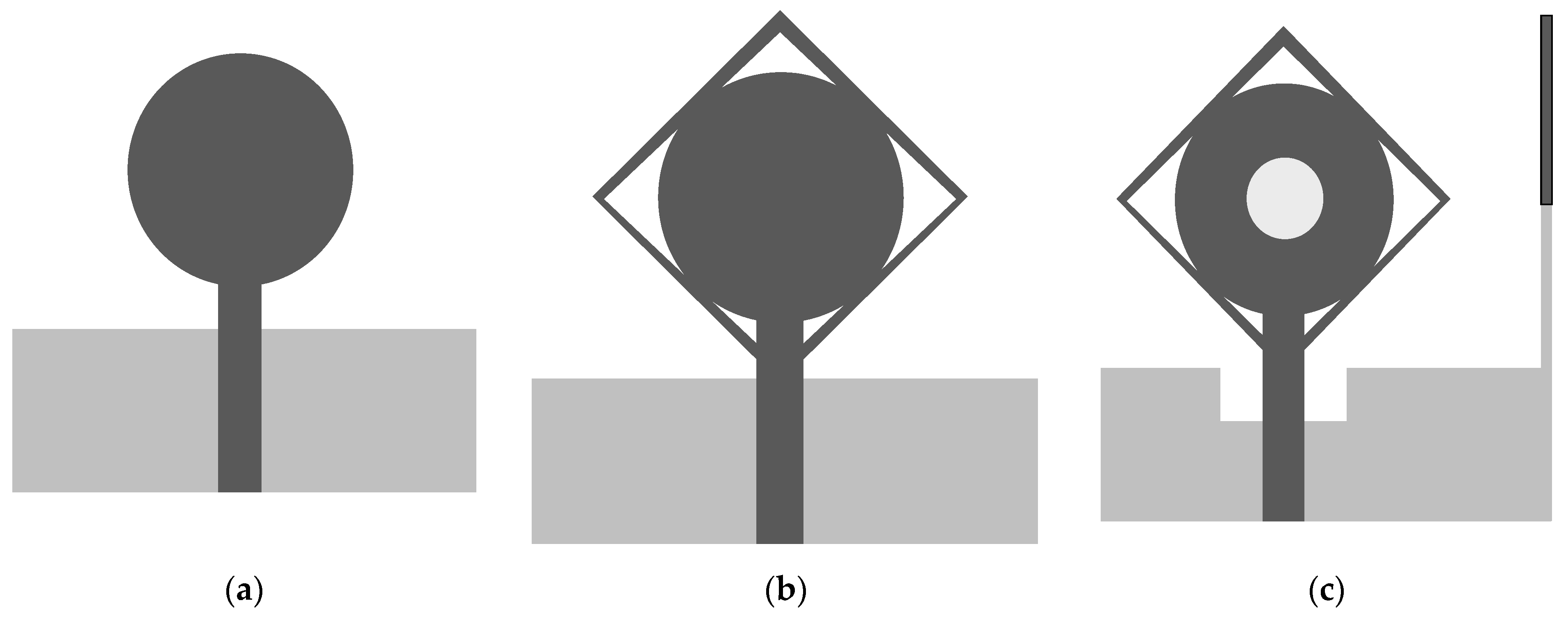
2.1. Antenna Geometry

A single element antenna with SWB is shown in Figure 1. Antenna fabrication is performed on the FR4 substrate (εr = 4.3, tan δ = 0.02) with a thickness of 1.2 mm. Monopole structure introduced for SWB, feedline width Wf is 1.5 mm to achieve 50 Ω characteristic with the dimension of 30 × 20 mm2. The dimensional details of the antenna resonating element are presented in Table 1. The development and optimization of the antenna was performed by using the CST MWS. The SWB antenna was investigated on three different design stages: Type I, Type II, and Type III, which can be observed from Figure 2. Type I is derived from a conventional circular monopole antenna. The circular shape was used in many UWB antennas to find wideband results. A circular radiation patch integrated with a square ring forms type II to achieve wide bandwidth. By etching in the radiation patch and ground plane with the additional stub, we achieved type III. Three stage design structures are shown in Figure 2. The initial antenna performed poorly; some significant contributions have been made in Type I to meet desired results. Type II structure gives bandwidth on the higher frequencies, which helps to expend the bandwidth. For better results, etching in the ground plane significantly improves performance. The reflection coefficient of the three stage designs is shown in Figure 3. The proposed antenna is optimized through simulation, exhibiting a bandwidth of 2.3 to 23 GHz.
Design optimization is started by the investigation of a single monopole antenna. The single antenna element was optimized to achieve the same results for MIMO systems (two-port and four-port antenna). While investigating the type I model, the circular radiation patch was introduced with the square ring. The addition of the square ring improves frequency bandwidth. Then, subtracting the center portion of the circular radiation patch current distribution was disturbed, which increased the effective inductance and capacitance for minimizing the lowest operating frequency from 3.6 to 2.3 GHz. To find the effective area of the radiation patch, the empirical formula for the lower cut-off frequency is used for a planar monopole antenna [32,33].
A = π * r 2     ,     A = a 2
C = 2 * A r     ,     ε e f f ε r + 1 2
f L = c λ     c 2 * C ε e f f GHz
where r is the radius and C is the circumference of the circle, εeff is the effective dielectric of the patch. We can drive the lower cut-off frequency from the above formulas, as we observe from simulation that proposed antenna fL is 2.3 GHz, which is also approximately equal through the above equation. To analyze the antenna performance, parametric analysis is performed to optimize the dimensions of different parameters. To calculate the dimension of the feedline, we analyze it through a simulation process. We find the best results on 1.5 mm feedline width as described in Figure 4a that the −10 dB bandwidth is achieved in an entire frequency band. For SWB, the square ring performed a vital role in expanding the antenna’s bandwidth. Figure 4b shows the impact of the square ring width on the reflection coefficient. If we increase the width of the square ring, the bandwidth range compromises on higher frequencies, and by decreasing the width of the square ring, it bring off 10 dB from 8 GHz to 11 GHz considering all other parameters fixed. Figure 5 demonstrates the substrate height optimization. It was observed from the simulation that substrate height has a significant effect on the results of the high frequencies. Frequency bandwidth was compromised from 12 GHz to 18 GHz to achieve 10 dB reflection coefficient at the entire frequency band but achieved better impedance matching results from 18 to 21 GHz by increasing the substrate height. By decreasing the substrate height, frequency bandwidth is compromised to achieve 10 dB at low frequencies. It is also known that the bandwidth is generally proportional to substrate thickness and inversely proportional to substrate permittivity. Figure 6 shows the current distribution effect at three different frequencies. Current density is maximum on edges of the radiation patch, feedline, and center of the ground plan. The current concentration is mainly on the bottom of the feedline, radiation patch edges, and ground plane at low frequencies. By moving at high frequencies, the current distribution is mainly on the edges of the radiation patch, varying slightly upwards on feedline and center of the ground plan. At higher frequencies, ground plane stub only shows current on internal edges, it helps in MIMO structure to improve isolation between the radiating elements.

2.2. SWB Antenna with Four Ports
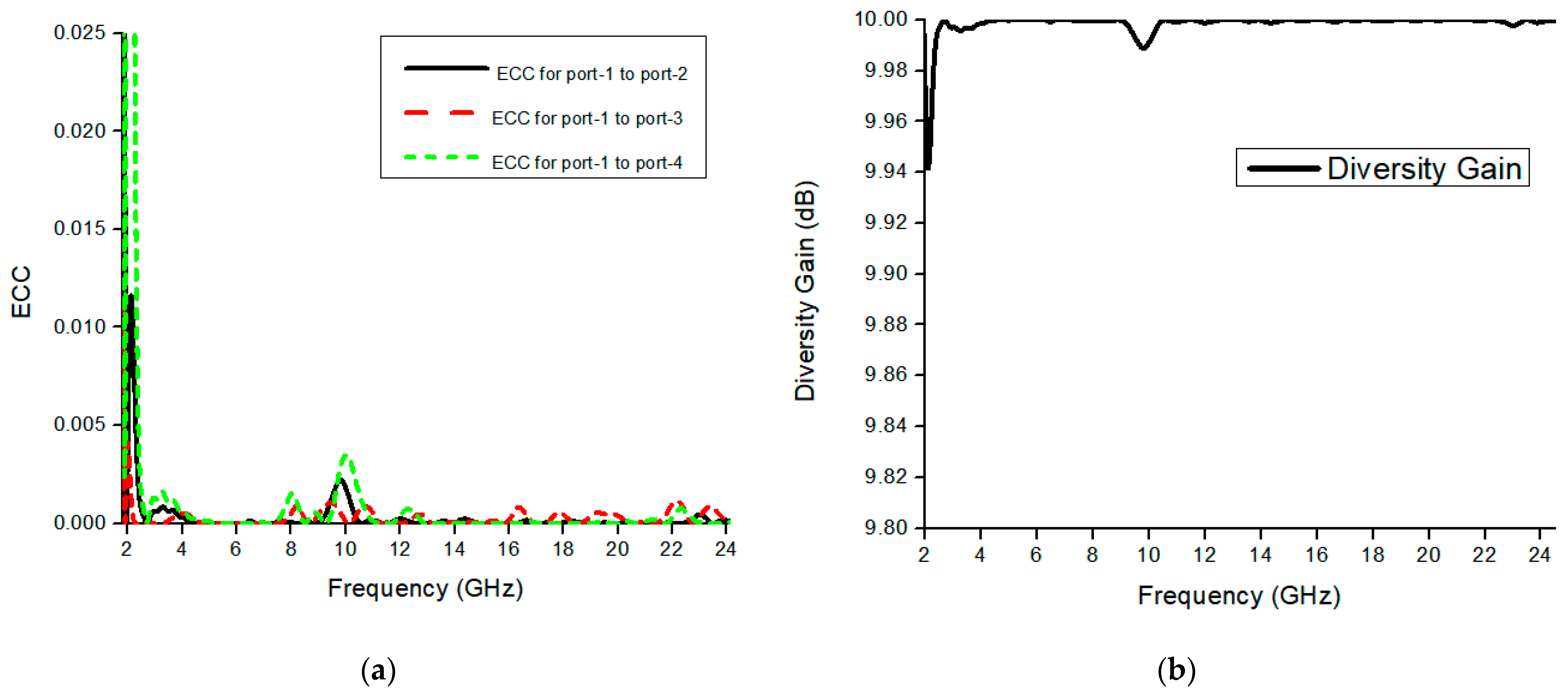
The geometry of the proposed SWB-MIMO antenna system is shown in Figure 7, and antenna elements are arranged orthogonally. MIMO radiation element and ground plane are the same as defined in the single antenna. The size of the proposed SWB-MIMO antenna is 60 × 55 × 1.2 mm3, where L1 is 60 mm and W1 is 55 mm. Compared with single and two-port MIMO antennas, a four-port MIMO antenna design is more critical due to the mutual coupling of antenna elements. The basic antenna model was designed in such a way that it controlled mutual coupling between antenna elements with the ground stub, and for high isolation, antenna elements are arranged orthogonally in adjustment. The proposed MIMO antenna is first analyzed with a mirror fashion structure. The width of the MIMO antenna was reduced by 15 mm (i.e., 60 × 40 × 1.2 mm3) but the isolation level was lower than the orthogonal structure. The simulated scattering parameters of the SWB-MIMO antenna are shown in Figure 8a. Furthermore, it shows that an isolation level higher than 20 dB is achieved over 90% of the entire frequency range, as shown in Figure 8b. The MIMO antenna shows good agreement in reflection coefficient with the single antenna model.

Diversity Analysis

The envelope correlation coefficient is used to check the second port’s effect on the first port for diversity analysis. The acceptable limit for the ECC is ECC < 0.5, obtained ECC of the three-element MIMO antenna shown in Figure 9a, which is less than 0.002 throughout the band. The correlation between MIMO elements is small, which illustrates the SWB-MIMO antenna has very good diversity performance. ECC calculates the diversity gain according to the formula below [24].
Gian = 10 * 1 | ECC |
The diversity performance of the proposed SWB-MIMO antenna is illustrated in Figure 9b. The diversity gain of the MIMO antenna is almost nearly 10 dB within the frequency range knowing that it starts from 9.94 dB at 2 GHz, as shown in the figure.

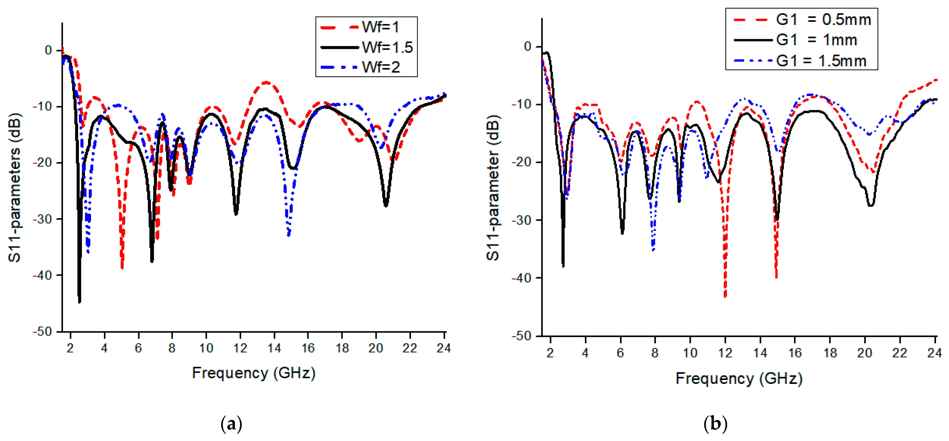
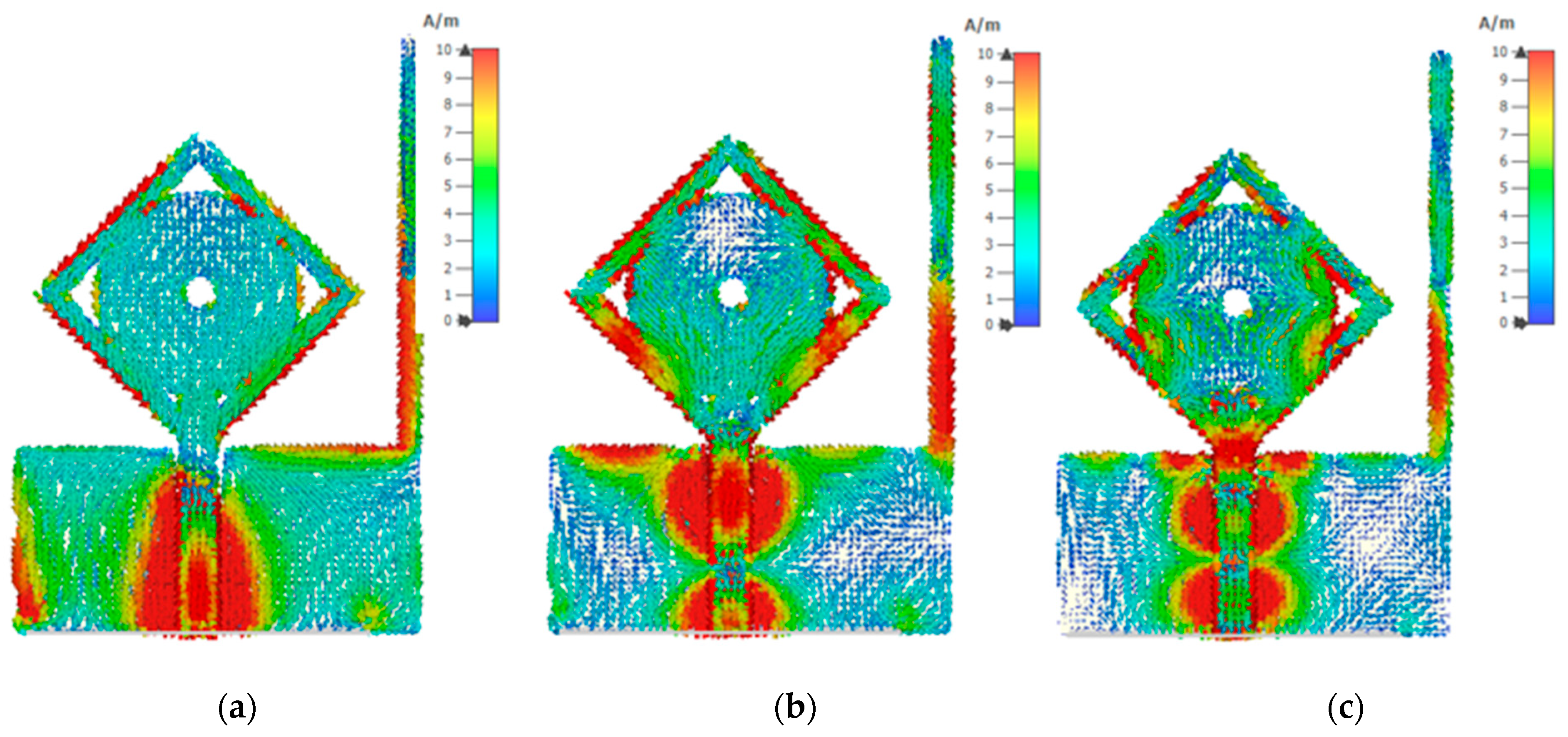
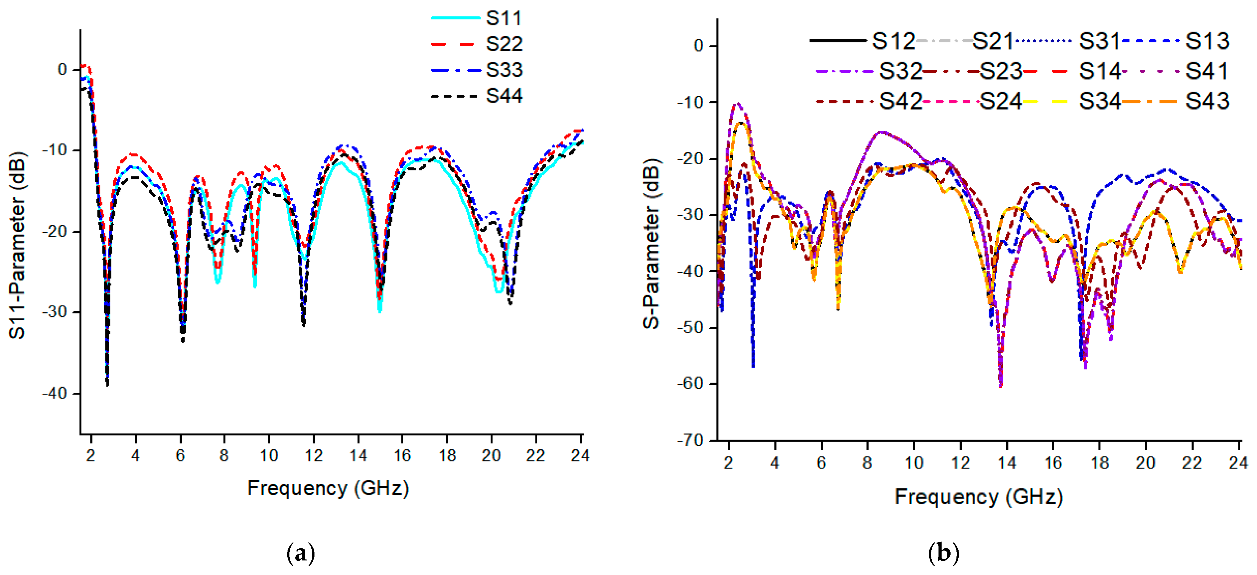
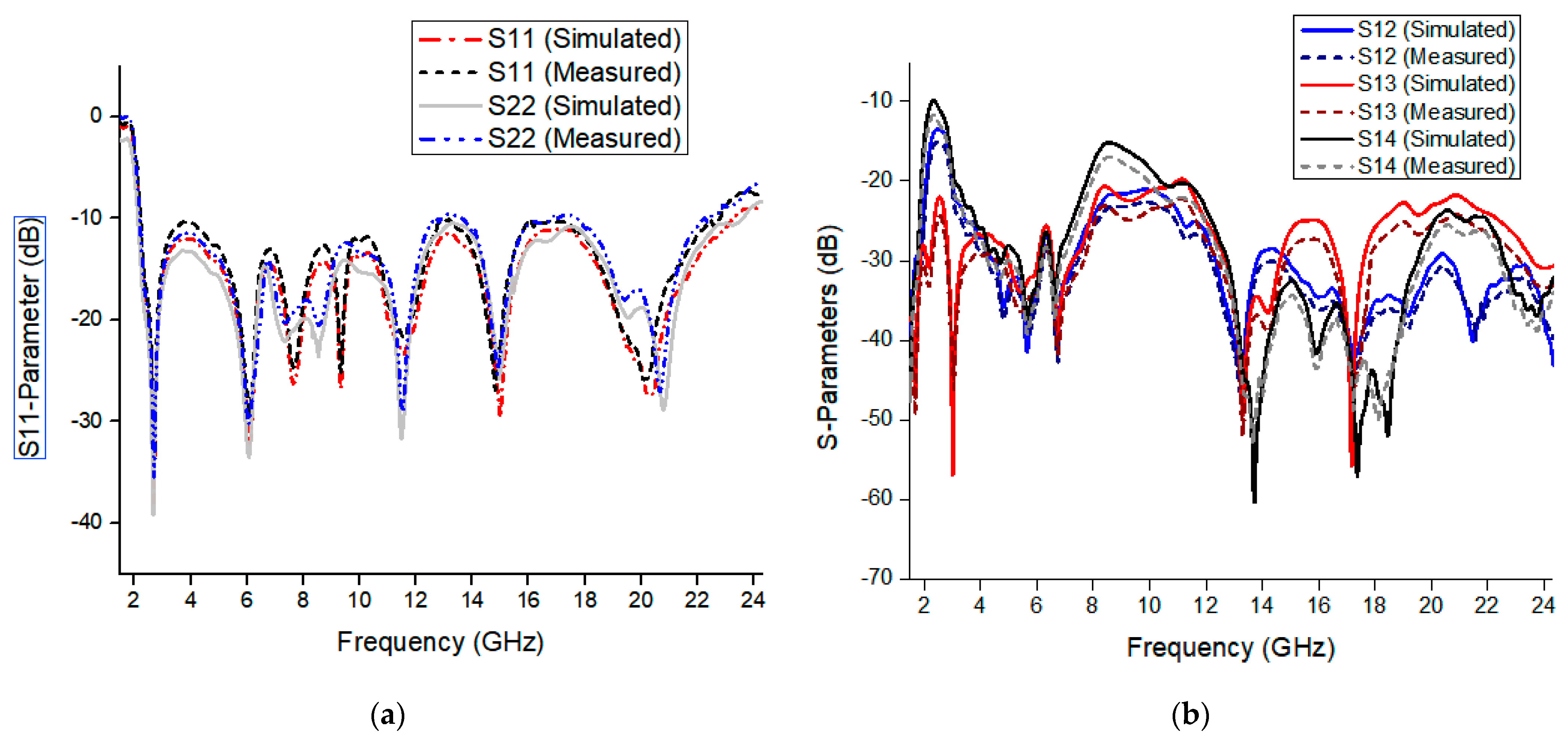
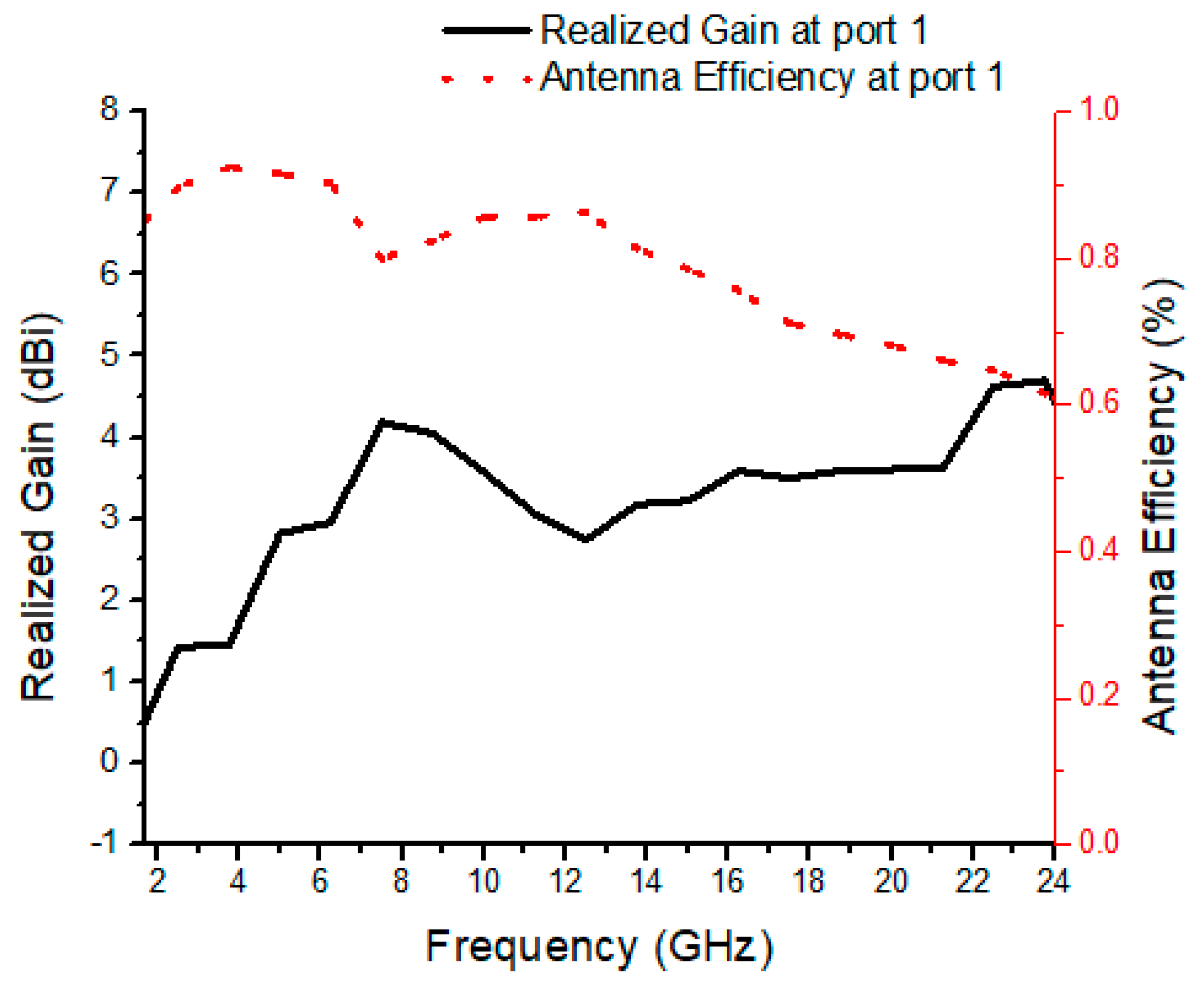
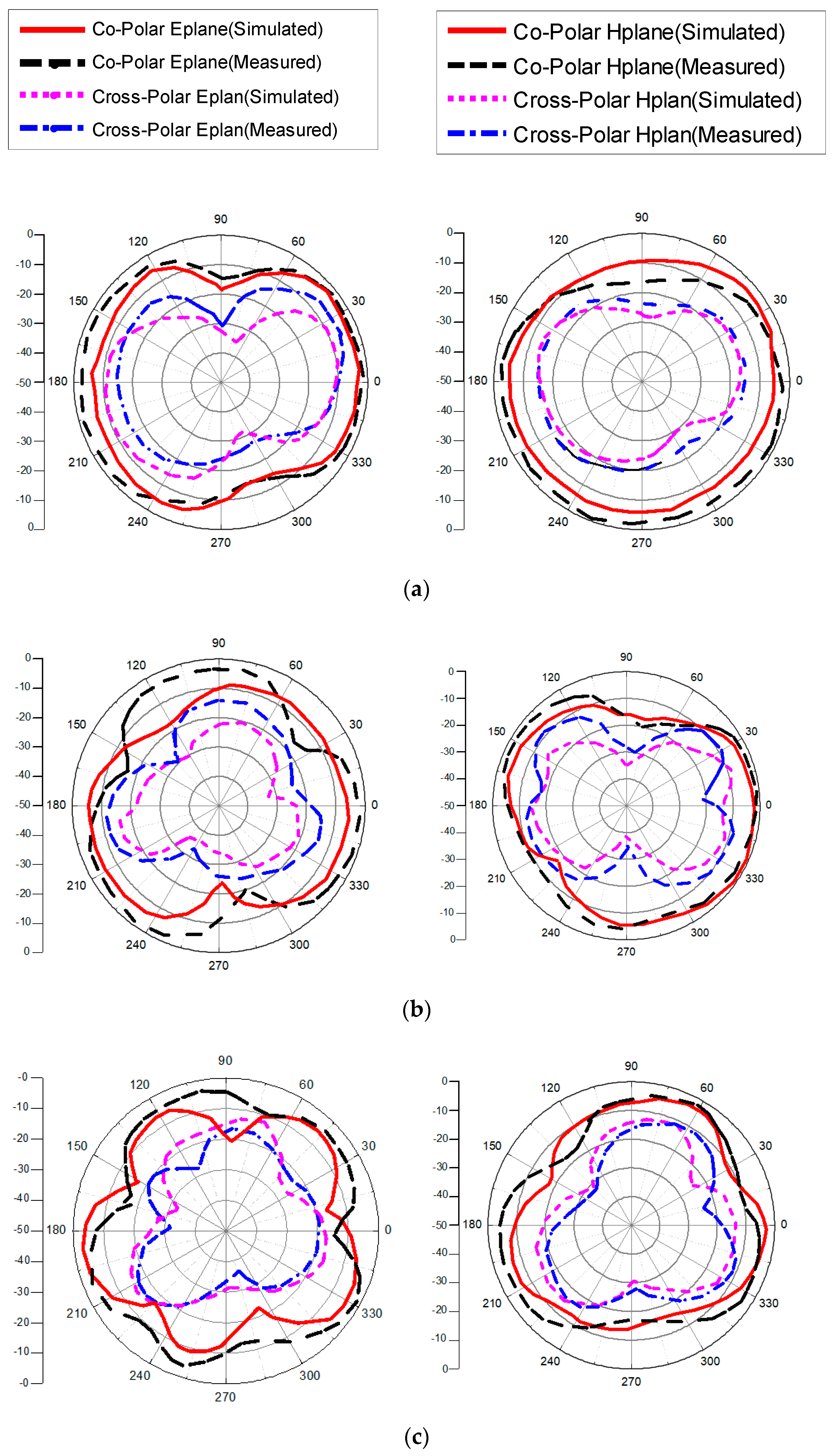
3. Results and Discussion

The fabricated prototype of the proposed antenna is shown in Figure 10. Agilent E8364B PNA analyzer is used to measure its performance. The antenna contains four monopoles in the orthogonal arrangement. The radiation patch of the antenna is connected with a 50 Ω feedline, which is in turn connected to match the 50 Ω SMA connector for antenna characterization for both fields. There are strong correlations between the measurement and simulation results of the prototype. Figure 11 shows the measured and simulated results of the reflection coefficient and mutual coupling of the proposed antenna. The frequency bandwidth of less than −10 dB is 2.3 to 23 GHz, which is appropriate for the requirement of reflection coefficient for indoor application, vehicle sensor, and high data-rate transmission. The isolation level of the proposed antenna is over 20 dB. Figure 12 shows the measured realized gain and antenna efficiency. The maximum antenna gain is 4.5 dBi and antenna efficiency ranges from 60% to 90% within the whole band.
The radiation properties of the proposed antenna are illustrated in Figure 13. The simulated and measured radiation characteristics for the E-plane (yz-plane) and the H-plane (xz-plane) are analyzed at different frequencies on port 1. The proposed MIMO antenna provides quasi-omnidirectional characteristics on co-polarized fields in E-plane and cross-polarization fields in H-plane because current distribution is uniform between ground plan and radiation patch at all frequencies. From Table 2, the comparison shows the proposed antenna is a suitable candidate with achieved characteristics. From the literature, it is observed by expending bandwidth other parameters are compromised in MIMO system. The comparison shows high isolation in [17], but its bandwidth is less than the proposed antenna. Although it has a compact structure, it only has two ports. In [22], SWB with high isolation is presented, but the proposed antenna has much better ECC than the design in [22]. The antennas in [25,26] have larger bandwidths than the proposed antenna, but the isolation and size is better in the proposed antenna.

4. Conclusions

This paper presents a novel SWB-MIMO antenna with high isolation, wide frequency bandwidth, and low ECC. To achieve the SWB, a square ring is placed within the radiation patch, which improves the impedance bandwidth. An orthogonal structure for a four-element SWB-MIMO antenna system is ideal for a high data-rate transmission. The operational frequency ranges from 2.3 to 23 GHz for single and multi-elements. A decoupling structure in the ground plane is introduced with an orthogonal adjustment to improve port isolation as high as over 20 dB. The simulated and measured results demonstrate quasi-omnidirectional radiation patterns, strong isolation, and minimum ECC. The proposed SWB-MIMO antenna system can potentially be used in high-speed data communications, IoT, and short-range communication systems.

Author Contributions

Conceptualization, J.D. and A.K.; methodology, J.D. and A.K.; validation, A.K. and M.S.A.; formal analysis, R.S.; investigation, A.K. and M.S.A.; resources, J.D.; data curation, J.D. and A.K.; writing—original draft preparation, A.K.; writing—review and editing, J.D. and R.S.; visualization, A.K. and M.S.A.; supervision, J.D. and R.S.; project administration, R.S.; funding acquisition, J.D. and R.S. All authors have read and agreed to the published version of the manuscript.

Funding

This research was funded in part by the National Natural Science Foundation of China, grant number 61801521 and 61971450, in part by the Natural Science Foundation of Hunan Province, grant number 2018JJ2533, and in part by the Fundamental Research Funds for the Central Universities, grant number 2018gczd014 and 20190038020050.

Conflicts of Interest

The authors declare no conflict of interest.

References

  1. Doll, A.; Harel, J.P. Technology Challenges in Massive-MIMO Radiating Platforms. In Proceedings of the 2017 Sixth Asia-Pacific Conference on Antennas and Propagation (APCAP), Xi’an, China, 16–19 October 2017. [Google Scholar]
  2. Federal Communications Commission. Revision of Part 15 of the Commission’s Rules Regarding Ultra-Wideband Transmission Systems; First Report and Order; Federal Communications Commission: Washington, DC, USA, 2002; pp. 2–48.
  3. Tang, Z.; Zhan, J.; Wu, X.; Xi, Z.; Wu, S. Simple ultra-wider-bandwidth MIMO antenna integrated by double decoupling branches and square-ring ground structure. Microw. Opt. Technol. Lett. 2020, 62, 1259–1266. [Google Scholar] [CrossRef]
  4. Jensen, M.A.; Wallace, J.W. A review of antennas and propagation for MIMO wireless communications. IEEE Trans. Antennas Propag. 2004, 52, 2810–2824. [Google Scholar] [CrossRef] [Green Version]
  5. Dhar, S.K.; Sharawi, M.S. A UWB semi-ring MIMO antenna with isolation enhancement. Microw. Opt. Technol. Lett. 2015, 57, 1941–1946. [Google Scholar] [CrossRef]
  6. Su, S.-W.; Lee, C.-T.; Chang, F.-S. Printed MIMO-antenna system using the neutralization-line technique for wireless USB-dongle applications. IEEE Trans. Antennas Propag. 2011, 60, 456–463. [Google Scholar] [CrossRef]
  7. Wong, H.S.; Kibria, S.; Islam, M.T. Hexa band Mimo antenna with neutralization line for LTE mobile device application. Microw. Opt. Technol. Lett. 2016, 58, 1198–1204. [Google Scholar]
  8. Chen, W.S.; Lin, C.-H.; Lee, B.-Y.; Hsu, W.-H.; Chang, F.-S. Monopole slot antenna design for WLAN MIMO application. Microw. Opt. Technol. Lett. 2012, 54, 1103–1107. [Google Scholar] [CrossRef]
  9. Yang, D.-G.; Kim, D.O.; Kim, C.-Y. Design of dual-band MIMO monopole antenna with high isolation using slotted CSRR for WLAN. Microw. Opt. Technol. Lett. 2014, 56, 2252–2257. [Google Scholar] [CrossRef]
  10. Obara, T.; Suyama, S.; Shen, J. Joint processing of analog fixed beamforming and CSI-based precoding for Super High bit rate massive MIMO transmission using higher frequency bands. IEICE Trans. Commun. 2015, E98-B, 1474–1481. [Google Scholar] [CrossRef]
  11. Plicanic, V.; Vasilev, I.; Tian, R. Capacity maximization of handheld MIMO terminal with adaptive matching in the indoor environment. IET Electron. Lett. 2011, 47, 900–901. [Google Scholar] [CrossRef] [Green Version]
  12. Vasilev, I.; Plicanic, V.; Lau, B.K. Impact of antenna design on MIMO performance for compact terminals with adaptive impedance matching. IEEE Trans. Antennas Propag. 2016, 64, 1454–1465. [Google Scholar] [CrossRef] [Green Version]
  13. Okan, T. A compact octagonal-ring monopole antenna for super wideband applications. Microw. Opt. Technol. Lett. 2020, 62, 1237–1244. [Google Scholar] [CrossRef]
  14. Alluri, S.; Nakkeeran, R. Compact high bandwidth dimension ratio steering-shaped super wideband antenna for future wireless communication applications. Microw. Opt. Technol. Lett. 2020, 62, 3985–3991. [Google Scholar] [CrossRef]
  15. Singhal, S.; Singh, A.K. CPW-fed hexagonal Sierpinski super wideband fractal antenna. IET Microw. Antennas Propag. 2016, 10, 1701–1707. [Google Scholar] [CrossRef]
  16. Aziz, S.Z.; Jamlos, M.F. Compact super wideband patch antenna design using diversities of reactive loaded technique. Microw. Opt. Technol. Lett. 2016, 58, 2811–2814. [Google Scholar] [CrossRef]
  17. Ul Haq, M.A.; Koziel, S. Feedline Alterations for Optimization-Based Design of Compact Super-Wideband MIMO Antennas in Parallel Configuration. IEEE Antennas Wirel. Propag. Lett. 2019, 18, 1986–1990. [Google Scholar] [CrossRef]
  18. Mathur, R.; Dwari, S. Compact 4-Port MIMO/diversity antenna with low correlation for UWB application. Frequenz 2018, 72, 429–435. [Google Scholar] [CrossRef]
  19. Tripathi, S.; Mohan, A.; Yadav, S. A compact Koch fractal UWB MIMO antenna with WLAN band-rejection. IEEE Antennas Wirel. Propag. Lett. 2015, 14, 1565–1568. [Google Scholar] [CrossRef]
  20. Sipal, D.; Abegaonkar, M.P.; Koul, S.K. Easily extendable compact planar UWB MIMO antenna array. IEEE Antennas Wirel. Propag. Lett. 2017, 16, 2328–2331. [Google Scholar] [CrossRef]
  21. Yu, C.; Yang, S.; Chen, Y.; Wang, W.; Zhang, L.; Li, B.; Wang, L. A super-wideband and high isolation MIMO antenna system using a windmill-shaped decoupling structure. IEEE Access 2020, 8, 115767–115777. [Google Scholar] [CrossRef]
  22. Kumar, P.; Urooj, S.; Malibari, A. Design and Implementation of Quad-Element Super-Wideband MIMO Antenna for IoT Applications. IEEE Access 2020, 8, 226697–226704. [Google Scholar] [CrossRef]
  23. Oni, M.A.I.; Shehab, S.H.; Hassan, S.; Dey, S. Design and analysis of a low-profile, elliptical patch Super Wide Band (SWB) MIMO antenna. In Proceedings of the 2015 International Conference on Advances in Electrical Engineering (ICAEE), Dhaka, Bangladesh, 17–19 December 2015. [Google Scholar]
  24. Hassan, M.M.; Rasool, M.; Asghar, M.U.; Zahid, Z.; Khan, A.A.; Rashid, I.; Rauf, A.; Bhatti, F.A. A novel UWB MIMO antenna array with band notch characteristics using parasitic decoupler. J. Electromagn. Waves Appl. 2020, 34, 1225–1238. [Google Scholar] [CrossRef]
  25. Raheja, D.K.; Kanaujia, B.K.; Kumar, S. Low profile four-port super-wideband multiple-input-multiple-output antenna with triple-band rejection characteristics. Int. J. RF Microw. Comput.-Aided Eng. 2019, 29, e21831. [Google Scholar] [CrossRef]
  26. Kumar, P.; Urooj, S.; Alrowais, F. Design of quad-port MIMO/Diversity antenna with triple-band elimination characteristics for super-wideband applications. Sensors 2020, 20, 624. [Google Scholar] [CrossRef] [PubMed] [Green Version]
  27. Sharma, M.; Dhasarathan, V.; Patel, S.K.; Nguyen, T.K. An ultra-compact four-port 4 × 4 super-wideband MIMO antenna including mitigation of dual notched bands characteristics designed for wireless network applications. AEU Int. J. Electron. Commun. 2020, 123, 153332. [Google Scholar] [CrossRef]
  28. Khan, M.I.; Khattak, M.I.; Rahman, S.U.; Qazi, A.B.; Telba, A.A.; Sebak, A. Design and Investigation of Modern UWB-MIMO Antenna with Optimized Isolation. Micromachines 2020, 11, 432. [Google Scholar] [CrossRef] [PubMed] [Green Version]
  29. Singhal, S. Feather-shaped super wideband MIMO antenna. Int. J. Microw. Wirel. Technol. 2021, 13, 94–102. [Google Scholar] [CrossRef]
  30. Namani, S.; Gonen, B. Smart Agriculture Based on IoT and Cloud Computing. In Proceedings of the 2020 3rd International Conference on Information and Computer Technologies (ICICT), San Jose, CA, USA, 9–12 March 2020. [Google Scholar]
  31. Ahad, A.; Tahir, M.; Sheikh, M.A.; Ahmed, K.I.; Mughees, A.; Numani, A. Technologies trend towards 5G network for smart health-care using IoT: A review. Sensors 2020, 20, 4047. [Google Scholar] [CrossRef]
  32. Balani, W.; Sarvagya, M.; Samasgikar, A.; Ali, T.; Kumar, P. Design and Analysis of Super wideband Antenna for Microwave Applications. Sensors 2021, 21, 477. [Google Scholar] [CrossRef]
  33. Sayidmarie, K.H.; Fadhel, Y.A. Design aspects of UWB printed elliptical monopole antenna with impedance matching. In Proceedings of the 2012 Loughborough Antennas & Propagation Conference (LAPC), Loughborough, UK, 12–13 November 2012; pp. 1–4. [Google Scholar]
Figure 1. Geometry of the proposed single-element antenna. (a) Front view, (b) radiation patch elements, and (c) back view.
Micromachines 13 00514 g001
Figure 2. Antenna investigation analysis (a) Type I, (b) Type II, and (c) Type III.
Micromachines 13 00514 g002
Figure 3. Reflection coefficients of the design phases.
Micromachines 13 00514 g003
Figure 4. Simulation response of (a) feedline and (b) square ring.
Micromachines 13 00514 g004
Figure 5. Simulation response of substrate height.
Micromachines 13 00514 g005
Figure 6. Surface current distribution of the antenna at (a) 5 GHz, (b) 12 GHz, and (c) 20 GHz.
Micromachines 13 00514 g006
Figure 7. MIMO SWB antenna. (a) Radiation patch and (b) ground plane.
Micromachines 13 00514 g007
Figure 8. Simulation response of the orthogonal MIMO antenna. (a) S-parameters and (b) mutual coupling.
Micromachines 13 00514 g008
Figure 9. Simulation response of the orthogonal MIMO antenna. (a) ECC and (b) diversity gain.
Micromachines 13 00514 g009
Figure 10. Fabricated prototype of MIMO antenna. (a) View from the top and (b) view from the bottom.
Micromachines 13 00514 g010
Figure 11. Measured and simulated S-parameters of the proposed MIMO antenna with respect to port1. (a) S-parameters and (b) isolation.
Micromachines 13 00514 g011
Figure 12. Measured realized gain and efficiency of the MIMO antenna port 1.
Micromachines 13 00514 g012
Figure 13. Simulated and measured response of co- and cross-polar radiation of the MIMO antenna on port 1 at the frequencies (a) 3.5 GHz, (b) 8 GHz, (c) 12 GHz, (d) 16 GHz, and (e) 21 GHz.
Micromachines 13 00514 g013aMicromachines 13 00514 g013b
Table 1. Proposed antenna dimension.
ParameterDimension (mm)ParameterDimension (mm)
L30Y53
W20R15
X10.5R21
X28.25G11
X33A17
X41A28
Y112X59
Y212.1X67.5
Y39X73
Y421X80.5
Table 2. Comparison of the proposed MIMO antenna with other reported antennas.
Ref.BandwidthDimensionsIsolation
(dB)
ECC
GHzRatiomm2λL × λL
(Lower
Frequency)
[2]3–186:140 × 400.30λ × 0.30λ>20<0.03
[17]2.8–207.1:117.7 × 30.70.13λ × 0. 23λ>22<0.005
[18]3.2–113.4:136 × 360.27λ × 0. 27λ>15<0.005
[19]2–10.65.3:145 × 450.34λ × 0. 34λ>17<0.005
[20]3–155:138 × 380.29λ × 0. 29λ>20<0.005
[21]2.9–4013.7:158 × 580.44λ × 0. 44λ>17<0.04
[22]1.3–4030.7:156 × 560.43λ × 0. 43λ>22<0.03
[23]2.24–3013.3:145 × 900.34λ × 0. 69λ>10N-A
[24]3.5–4.4, 6–204.5:167 × 670.51λ × 0.51λ>20<0.05
[25]0.96–3536:163 × 630.48λ × 0.48λ>17<0.01
[26]1.3–4031:163 × 630.48λ × 0.48λ>16<0.05
[27]3.1–20.36.4:150 × 500.38λ × 0.38λ>20<0.05
[28]3–4013.3:118 × 360.13λ × 0.27λ>18<0.01
[29]3.8–5113.3:531 × 310.23λ × 0.23λ>15<0.075
Proposed2.3–23 10:160 × 550.46λ × 0.42λ>20<0.002
Publisher’s Note: MDPI stays neutral with regard to jurisdictional claims in published maps and institutional affiliations.

