
Design and Performance Analysis of a Micro-Displacement Worktable Based on Flexure Hinges


Abstract
:1. Introduction
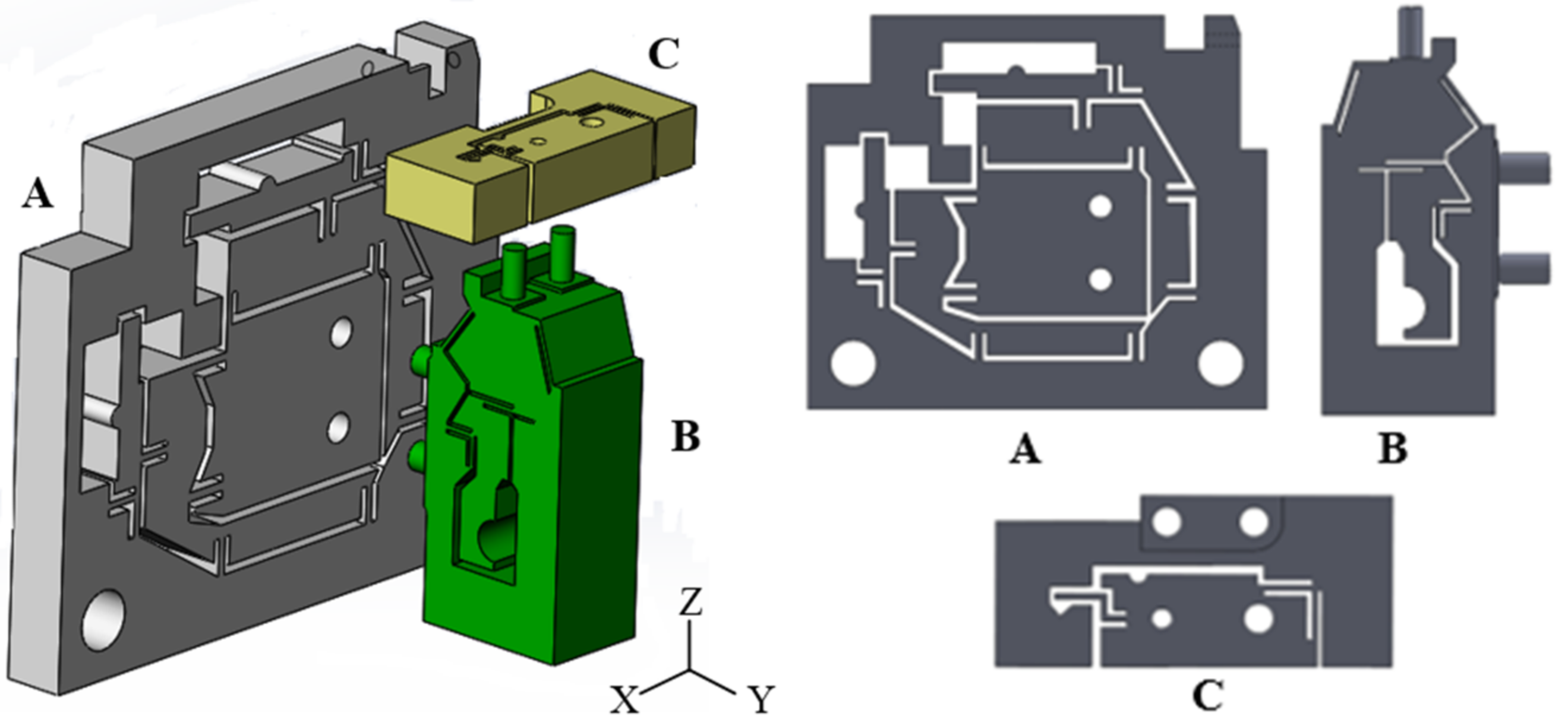
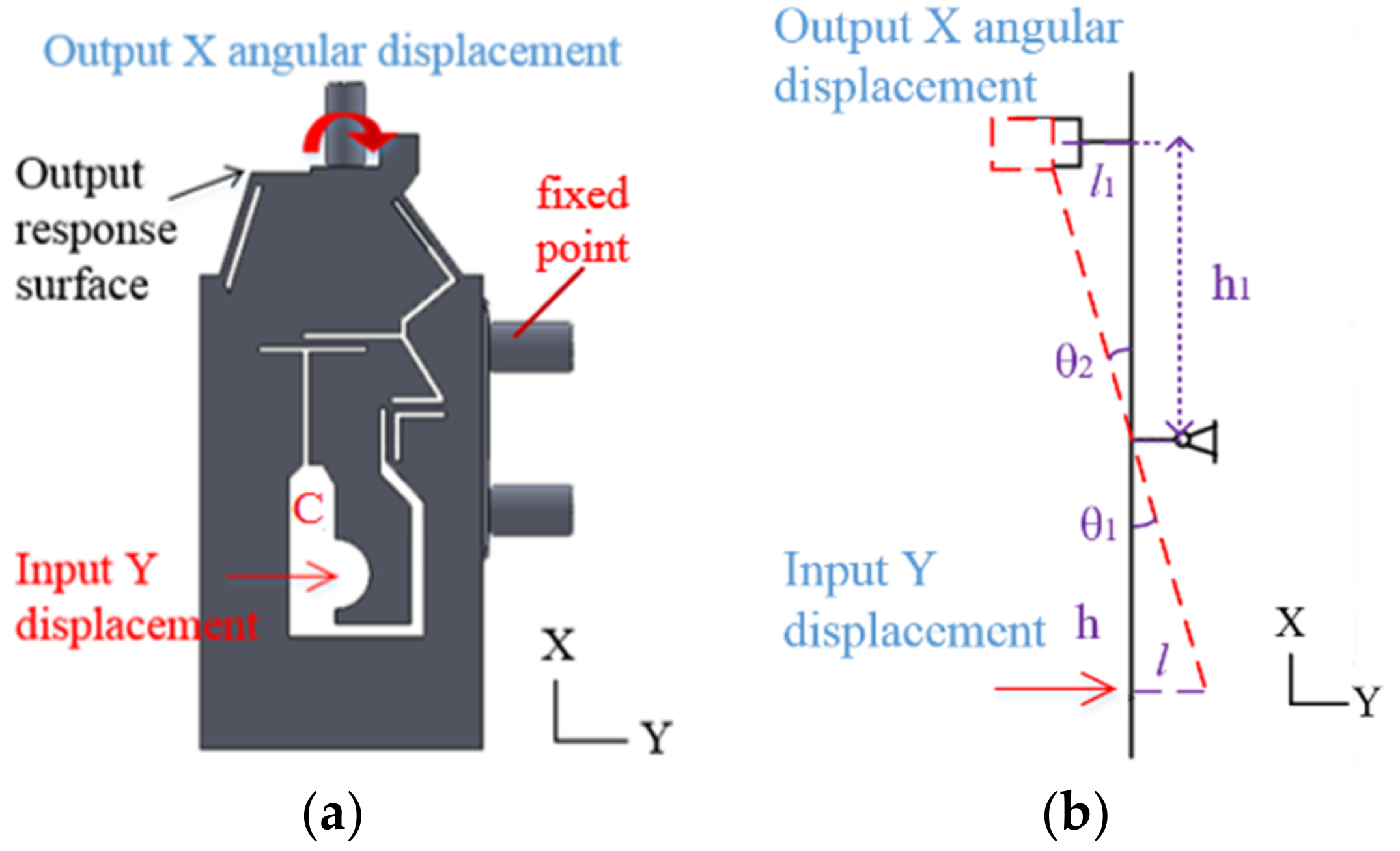
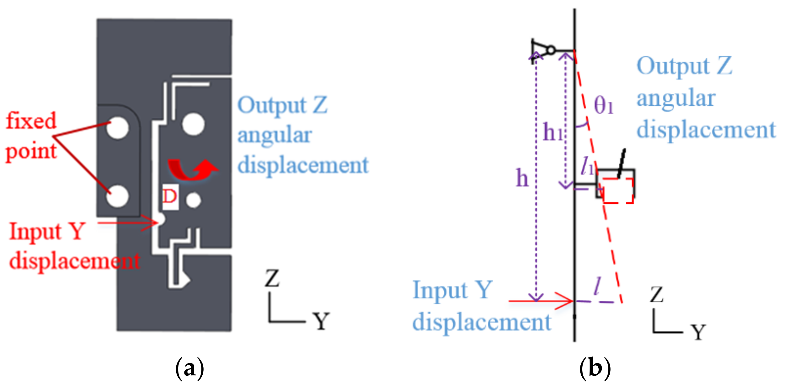
2. Design of Flexure Hinge Mechanisms
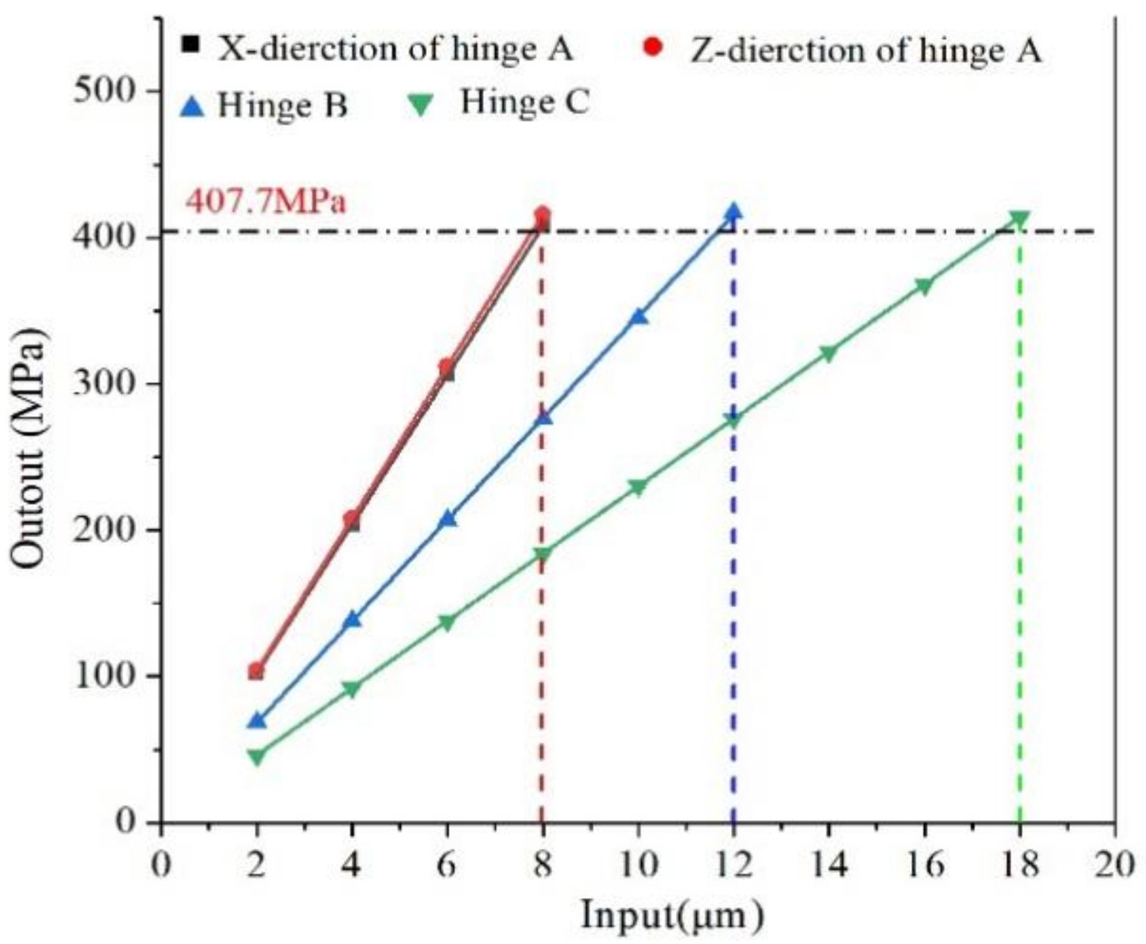
3. Finite Element Analysis
4. Experiment Tests
5. Experimental Results
6. Conclusions
Author Contributions
Funding
Institutional Review Board Statement
Informed Consent Statement
Data Availability Statement
Conflicts of Interest
References
- Zhang, Z.Y.; Yan, J.W.; Kuriyagawa, T. Manufacturing technologies toward extreme precision. Int. J. Extrem. Manuf. 2019, 1, 022001. [Google Scholar] [CrossRef] [Green Version]
- Kim, D.; Kang, D.; Gweon, D. Optimal design of a flexure hinge-based XYZ atomic force microscopy scanner for minimizing Abbe errors. Rev. Sci. Instrum. 2005, 76, 073706. [Google Scholar] [CrossRef] [Green Version]
- Kong, L.B.; Peng, X.; Chen, Y.; Wang, P.; Xu, M. Multi-sensor measurement and data fusion technology for manufacturing process monitoring: A literature review. Int. J. Extrem. Manuf. 2020, 2, 022001. [Google Scholar] [CrossRef]
- Liu, S.; Zhang, H.; Yin, R.; Zhang, W. Finite Element Analysis and Application of a Flexure Hinge Based Fully Compliant Prosthetic Finger. In ICSEE; Springer: Singapore, 2017; pp. 191–198. [Google Scholar] [CrossRef]
- Li, Z.; Chen, X.; Jin, G. Dimensionless design model for biaxial Cartwheel flexure hinges. Mech. Based Des. Struct. Mach. 2018, 46, 401–409. [Google Scholar] [CrossRef]
- Zhang, T.; Jiang, F.; Lan, Y.; Jiang, Z.Y.; Xu, X.P. A novel ultrahigh-speed ball-on-disc tribometer. Tribol. Int. 2021, 3, 106901. [Google Scholar] [CrossRef]
- Bi, S.; Zhao, S.; Zhu, X. Dimensionless design graphs for three types of annulus-shaped flexure hinges. Precis. Eng. 2010, 34, 659–666. [Google Scholar] [CrossRef]
- Paros, J.M. How to design flexure hinge. Mach. Des. 1965, 27, 151–157. [Google Scholar]
- Lobontiu, N. Corner-filleted flexure hinges. J. Mech. Des. 2001, 123, 346–352. [Google Scholar] [CrossRef]
- Lobontiu, N. Design of symmetric conic-section flexure hinges based on closed-form compliance equations. Mech. Mach. Theory 2002, 37, 477–498. [Google Scholar] [CrossRef]
- Lobontiu, N. Analytical model of displacement amplification and stiffness optimization for a class of flexure-based compliant mechanisms. Comput. Struct. 2003, 81, 2797–2810. [Google Scholar] [CrossRef]
- Wu, Y.; Zhou, Z. Design calculations for flexure hinges. Rev. Sci. Instrum. 2002, 73, 3101–3106. [Google Scholar] [CrossRef]
- Lin, R.; Zhang, X.; Long, X. Hybrid flexure hinges. Rev. Sci. Instrum. 2013, 84, 085004. [Google Scholar] [CrossRef] [PubMed]
- Pan, J.; Wu, J.; Zhang, Y.; Wang, H.; Tan, J. Design and Analyze of Flexure Hinges Based on Triply Periodic Minimal Surface Lattice. Precis. Eng. 2020, 68, 338–350. [Google Scholar] [CrossRef]
- Kong, J.; Huang, Z.; Xian, X.; Wang, Y.; Yu, P. Generalized model for conic-V-shaped flexure hinges. Sci. Prog. 2020, 103, 0036850420981211. [Google Scholar] [CrossRef] [PubMed]
- Wang, C.; Yang, F.; Nguyen, V.T.T.; Nguyen, Q.M.; Huynh, N.T.; Huynh, T.T. Optimal Design for Compliant Mechanism Flexure Hinges: Bridge-Type. Micromachines 2021, 12, 1304. [Google Scholar] [CrossRef] [PubMed]
- Qiu, L.; Liu, Y.; Yu, Y.; Bai, Y.B. Design and stiffness analysis of a pitch-varying folded flexure hinge (PFFH). Mech. Mach. Theory 2021, 157, 104187. [Google Scholar] [CrossRef]
- Li, L.; Zhang, D.; Qu, H.; Wang, Y. Generalized Model and Configuration Design of Multiple-Axis Flexure Hinges. Mech. Mach. Theory 2022, 169, 104677. [Google Scholar] [CrossRef]
- Sun, X.; Chen, W.; Tian, Y.; Fatikow, S. A novel flexure-based microgripper with double amplification mechanisms for micro/nano manipulation. Rev. Sci. Instrum. 2013, 84, 085002. [Google Scholar] [CrossRef] [PubMed]
- Li, J.; Liu, H.; Zhao, H. A compact 2-DOF piezoelectric-driven platform based on “z-shaped” flexure hinges. Micromachines 2017, 8, 245. [Google Scholar] [CrossRef] [PubMed] [Green Version]
- Shao, S.; Tian, Z.; Song, S.; Xu, M. Two-degrees-of-freedom piezo-driven fast steering mirror with cross-axis decoupling capability. Rev. Sci. Instrum. 2018, 89, 055003. [Google Scholar] [CrossRef] [PubMed]
- Qin, Y.; Shirinzadeh, B.; Zhang, D.; Tian, Y. Design and kinematics modeling of a novel 3-DOF monolithic manipulator featuring improved Scott-Russell mechanisms. J. Mech. Des. 2013, 135, 101004. [Google Scholar] [CrossRef]
- Lin, J.; Han, J.; Lu, M. Design and performance testing of a novel three-dimensional elliptical vibration turning device. Micromachines 2017, 8, 305. [Google Scholar] [CrossRef] [PubMed]
- Lee, J.C.; Lee, I.; Yang, S. Development of compact three-degrees-of-freedom compensation system for geometric errors of an ultra-precision linear axis. Mech. Mach. Theory 2016, 99, 72–82. [Google Scholar] [CrossRef]
- Zhao, Y.T.; Lu, J. Realization of Four-DOF Precision Adjustment Mechanism of Mirror with Flexure Hinge. Mach. Des. Res. 2007, 1, 61–64. [Google Scholar] [CrossRef]
- Chen, W.; Yang, S.; Liu, J.; Chen, W. Design of a novel 5-DOF flexure-based compound alignment stage for Roll-to-Roll Printed Electronics. Rev. Sci. Instrum. 2017, 88, 025002. [Google Scholar] [CrossRef]
- Hesselbach, J.; Raatz, A.; Wrege, J. Design and analysis of a macro parallel robot with flexure hinges for micro assembly tasks. In Proceedings of the 35th International Symposium on Robotics (ISR), Paris, France, 23–26 March 2004; pp. 23–26. [Google Scholar]
- Yun, Y.; Li, Y. Design and analysis of a novel 6-DOF redundant actuated parallel robot with compliant hinges for high precision positioning. Nonlinear Dyn. 2010, 61, 829–845. [Google Scholar] [CrossRef]
- Lu, K.; Tian, Y.; Liu, C.; Zhou, C.; Guo, Z.; Wang, F.; Zhang, D.; Shirinzadeh, B. Design of a novel 3D ultrasonic vibration platform with tunable characteristics. Int. J. Mech. Sci. 2020, 186, 105895. [Google Scholar] [CrossRef]
- Gräser, P.; Linß, S.; Harfensteller, F.; Torres, M.; Zentner, L.; Theska, R. High-precision and large-stroke XY micropositioning stage based on serially arranged compliant mechanisms with flexure hinges. Precis. Eng. 2021, 72, 469–479. [Google Scholar] [CrossRef]
- Gan, J.; Long, J.; Ge, M. Design of a 3DOF XYZ Bi-Directional Motion Platform Based on Z-Shaped Flexure Hinges. Micromachines 2021, 13, 21. [Google Scholar] [CrossRef] [PubMed]
- Cui, F.; Li, Y.; Qian, J. Development of a 3-DOF Flexible Micro-Motion Platform Based on a New Compound Lever Amplification Mechanism. Micromachines 2021, 12, 686. [Google Scholar] [CrossRef] [PubMed]
- Markovic, K.; Zelenika, S. Optimized cross-spring pivot congurations with minimized parasitic shifts and stiffness variations investigated via nonlinear FEA. Mech. Based Des. Struct. Mach. 2017, 45, 380–394. [Google Scholar] [CrossRef]
- Cai, K.; Tian, Y.; Wang, F.; Zhang, D.; Shirinzadeh, B. Development of a piezo-driven 3-DOF stage with T-shape flexure hinge mechanism. Robot. Comput.-Integr. Manuf. 2016, 37, 125–138. [Google Scholar] [CrossRef] [Green Version]
- Ivanov, I.; Corves, B. Characterization of Flexure Hinges Using the Script Oriented Programming within a FEM Software Application. In Mechanisms, Transmissions and Applications; Springer: Dordrecht, The Netherlands, 2012; pp. 225–233. [Google Scholar] [CrossRef]
- Ma, Z.C.; Du, J.; Ma, X.X.; Zhang, F. Fatigue device driven by a three degree of freedom tripodal piezoelectric actuator. Rev. Sci. Instrum. 2019, 90, 036102. [Google Scholar] [CrossRef] [PubMed]
- Hwang, E.J.; Min, K.S.; Song, S.H.; Ahn, I.H. Optimal design of a flexure-hinge precision stage with a lever. J. Mech. Sci. Technol. 2007, 21, 616–623. [Google Scholar] [CrossRef]
- Zhou, M.; Fan, Z.; Ma, Z.; Zhao, H.; Wu, D. Design and experimental research of a novel stick-slip type piezoelectric actuator. Micromachines 2017, 8, 150. [Google Scholar] [CrossRef] [Green Version]
- AISI 1045 Steel, Cold Drawn, 19–32 mm (0.75–1.25 in) Round. Available online: http://www.matweb.com (accessed on 10 January 2022).


| Worktable Design | Degree of Freedom | Maximum Displacement | Maximal Angle | Maximum Error of Simulation and Test Results | Characteristics of Worktable |
|---|---|---|---|---|---|
| Yan (2022) Design and performance analysis of a micro-displacement worktable based on flexure hinges | 4-DOF: X-direction Z-direction X-rotation Z-rotation | 1.67 µm 1.74 µm | 14.90° 18.58° | 6.0%, 2.0%, 1.7%, 3.4% | The worktable has a large displacement range, high precision, simple structure and adopts a flexible hinge with a round angle. |
| Zhao (2007) Realization of Four-DOF Precision Adjustment Mechanism of Mirror With Flexure Hinge | 4-DOF: Z-direction X-rotation Y-rotation Z-rotation | ±0.4 mm | ±0.08° ±0.5° ±0.06° | No simulation | The worktable has enough high resolution and adopts a single straight round flexible hinge. |
| Li (2017) A Compact 2-DOF Piezoelectric-Driven Platform Based on “Z-Shaped” Flexure Hinges | 2-DOF: X-direction Y-direction | 17.65 µm 15.45 µm | None | 2.03% 3.62% | The working stress of the worktable is the smallest, and the ‘Z’ flexible hinge is adopted. |
| Lin (2017) Design and Performance Testing of a Novel Three-Dimensional Elliptical Vibration Turning Device | 3-DOF: X-direction Y-direction Z-direction | 26 µm 24 µm 22 µm | None | 11.2% 11.1% 9.8% | This worktable has a compact structure with relatively large stroke and high working bandwidth, good tracking accuracy, relatively high resolution and low hysteresis, which is suitable for micro-nano processing. |
| Gan (2021) Design of a 3DOF XYZ Bi-Directional Motion Platform Based on Z-Shaped Flexure Hinges | 3-DOF: X-direction Y-direction Z-direction | ±125.58 µm ±126.37 µm ±568.45 µm | None | 5.67% 3.73% 12.74% | The workbench has a compact structure, large stroke and bidirectional movement, but it is relatively difficult to manufacture, has a high cost and it is difficult to control four actuators. |
| Modulus of Elasticity (GPa) | Poissons Ratio | Yield Strength (MPa) | Allowable Stress (MPa) | Elongation (%) | Density (g/mm3) |
|---|---|---|---|---|---|
| 206 | 0.29 | 530 | 407.7 | ≥12 | 7.85 |
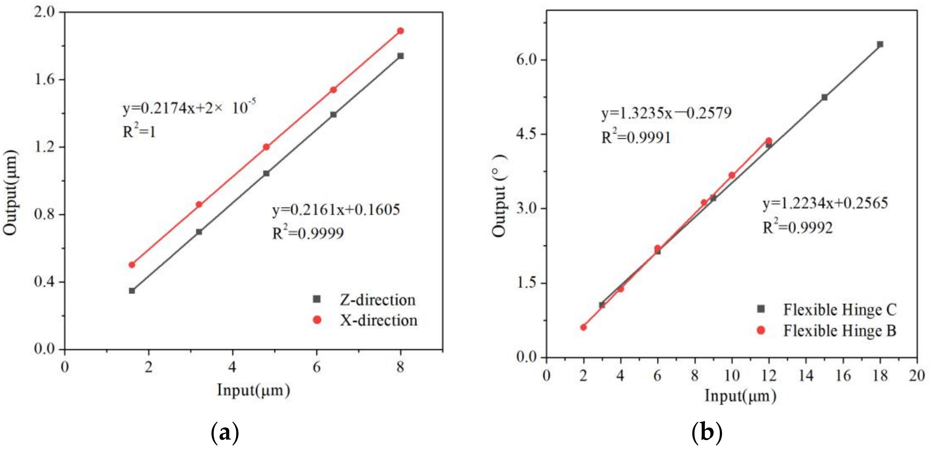
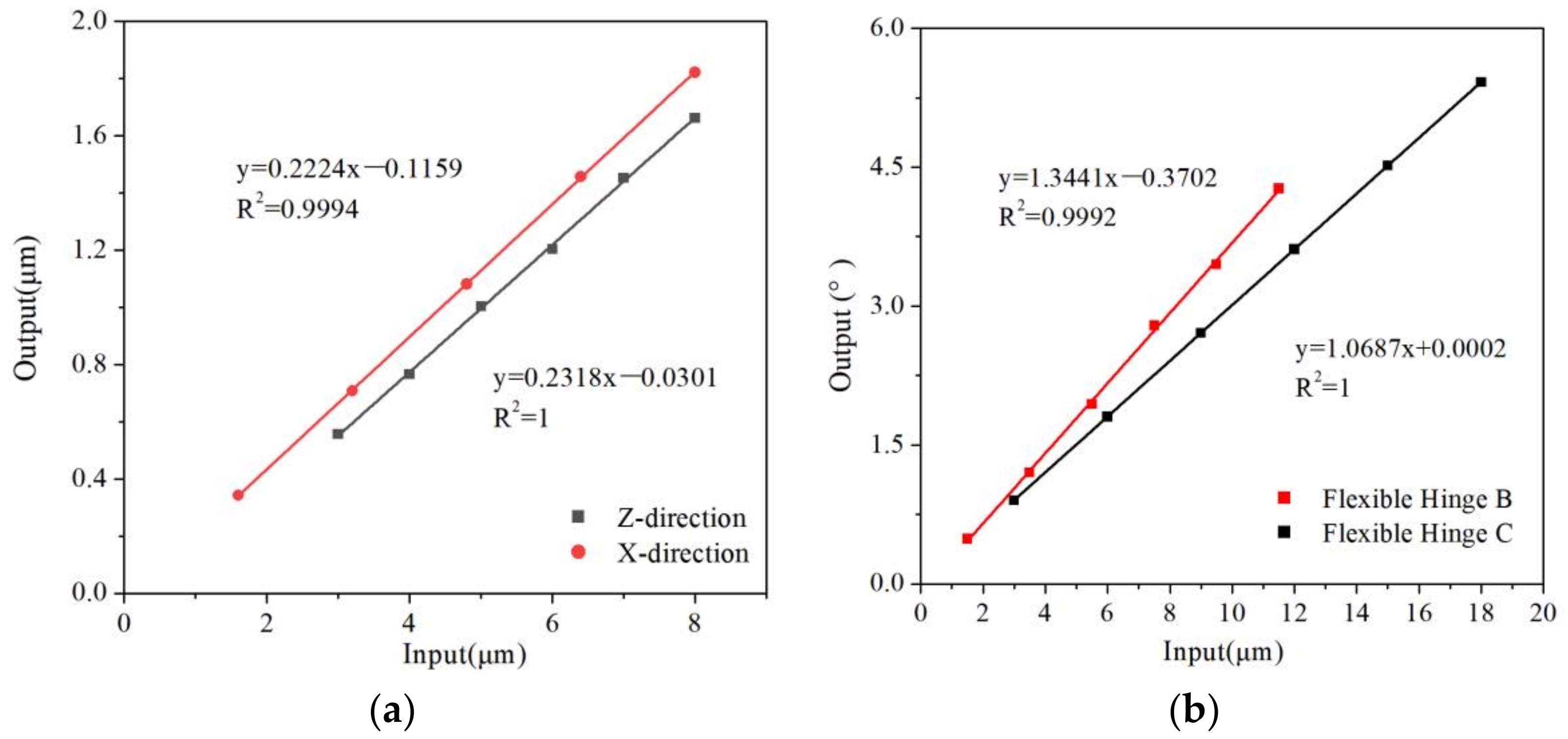
| Simulation of Single Flexure Hinge | Simulation (µm/°) | Simulation In/Out Ratio | Simulation of Flexure Hinge Assembly (µm/°) | Simulation In/Out Ratio |
|---|---|---|---|---|
| X-direction of hinge A | 1.73 | 0.2174 | 0.2195 | 0.2174 |
| Z-direction of hinge A | 1.88 | 0.2161 | 0.2087 | 0.2161 |
| Hinge B | 4.37 | 1.3235 | 1.3774 | 1.3235 |
| Hinge C | 6.20 | 1.2234 | 1.2649 | 1.2234 |
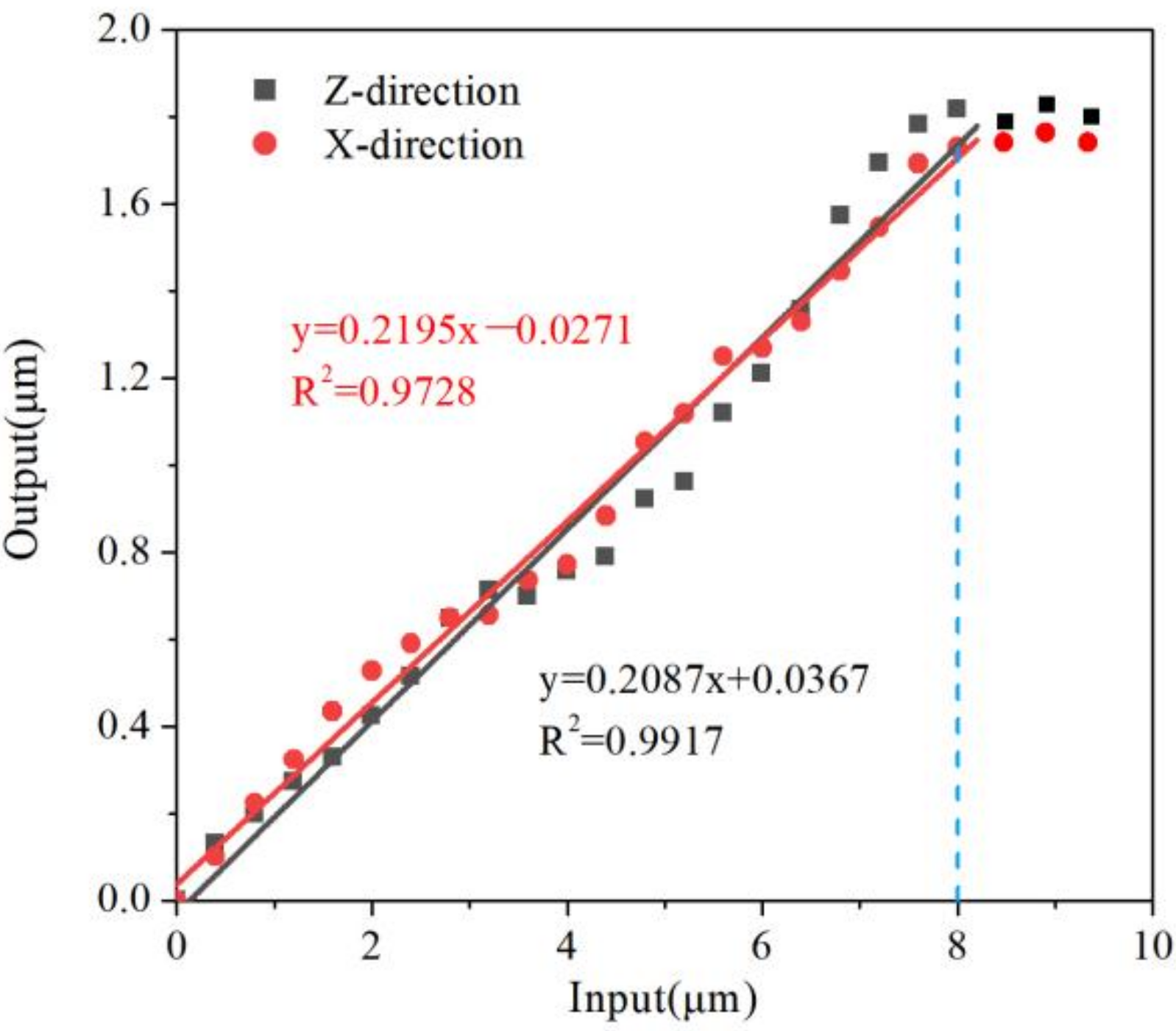
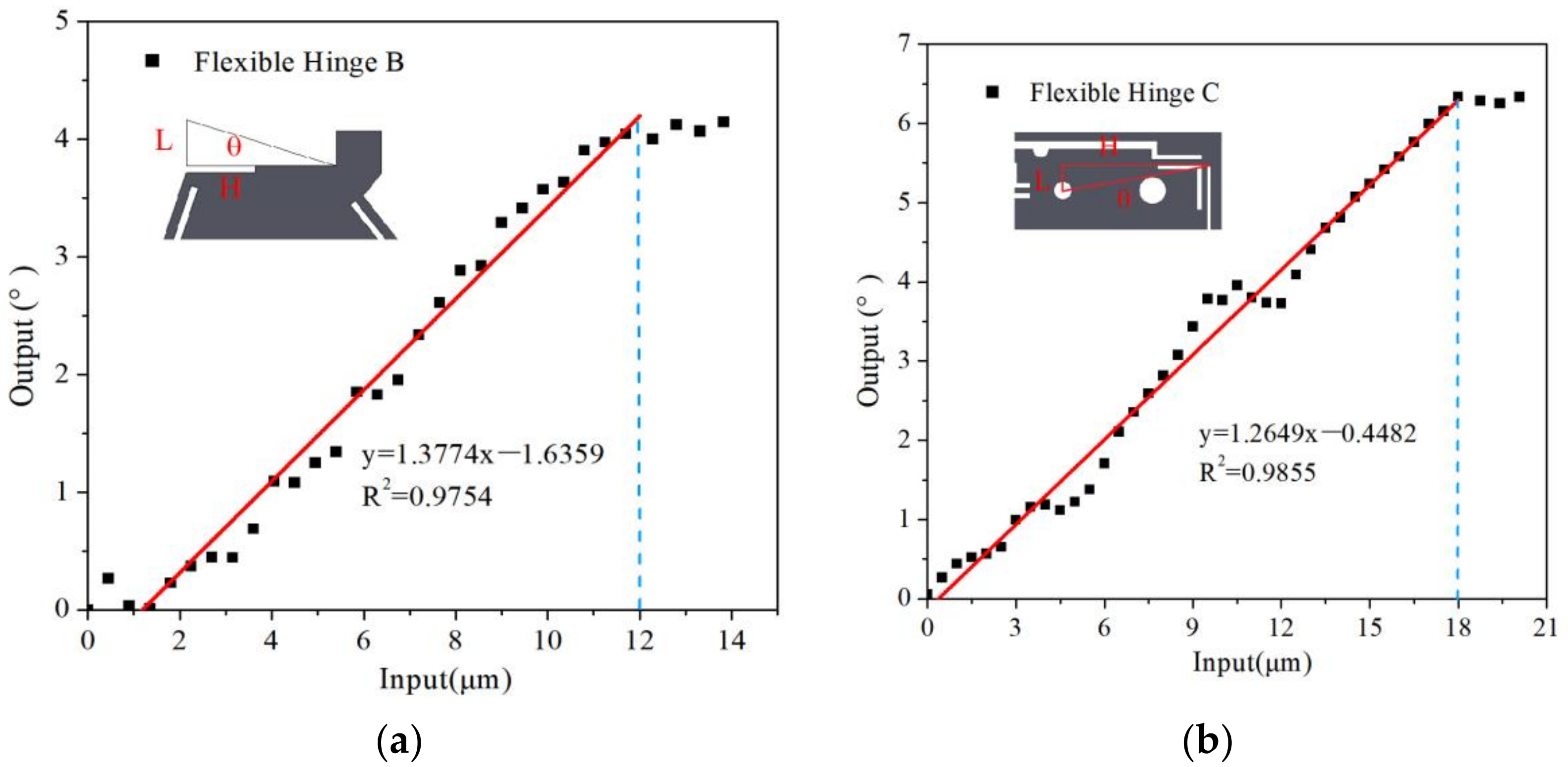
| Experimental of Single Flexure Hinge | Experimental (µm/°) | Error (%) | Experimental of Flexure Hinge Assembly (µm/°) | Error (%) |
|---|---|---|---|---|
| X-direction of hinge A | 1.67 | 3.5 | 1.67 | 6 |
| Z-direction of hinge A | 1.76 | 6.4 | 1.74 | 2 |
| Hinge B | 4.25 | 1.7 | 4.20 | 1.7 |
| Hinge C | 6.28 | 1.4 | 5.23 | 3.4 |
Publisher’s Note: MDPI stays neutral with regard to jurisdictional claims in published maps and institutional affiliations. |
© 2022 by the authors. Licensee MDPI, Basel, Switzerland. This article is an open access article distributed under the terms and conditions of the Creative Commons Attribution (CC BY) license (https://creativecommons.org/licenses/by/4.0/).
Share and Cite
Yan, L.; Jiang, A.; Jiang, F.; Liu, G.; Wang, F.; Wu, X. Design and Performance Analysis of a Micro-Displacement Worktable Based on Flexure Hinges. Micromachines 2022, 13, 518. https://doi.org/10.3390/mi13040518
Yan L, Jiang A, Jiang F, Liu G, Wang F, Wu X. Design and Performance Analysis of a Micro-Displacement Worktable Based on Flexure Hinges. Micromachines. 2022; 13(4):518. https://doi.org/10.3390/mi13040518
Chicago/Turabian StyleYan, Lan, Anna Jiang, Feng Jiang, Guangda Liu, Fuzeng Wang, and Xian Wu. 2022. "Design and Performance Analysis of a Micro-Displacement Worktable Based on Flexure Hinges" Micromachines 13, no. 4: 518. https://doi.org/10.3390/mi13040518