
Facile Synthesis of Mesoporous Silica at Room Temperature for CO2 Adsorption


Abstract
:
1. Introduction
2. Materials and Methods
2.1. Materials
2.2. Porous Silica Synthesis Using the Calcination Process
2.3. Porous Silica Synthesis Using the Room-Temperature Process
2.4. Introduction of Amine Group
2.5. Characterization
3. Results and Discussion
4. Conclusions
Supplementary Materials
Author Contributions
Funding
Data Availability Statement
Conflicts of Interest
References
- Montoro, C.; Linares, F.; Procopio, E.Q.; Senkovska, I.; Kaskel, S.; Galli, S.; Masciocchi, N.; Barea, E.; Navarro, J.A.R. Capture of Nerve Agents and Mustard Gas Analogues by Hydrophobic Robust MOF-5 Type Metal–Organic Frameworks. J. Am. Chem. Soc. 2011, 133, 11888–11891. [Google Scholar] [CrossRef]
- Hussin, F.; Aroua, M.K. Recent trends in the development of adsorption technologies for carbon dioxide capture: A brief literature and patent reviews (2014–2018). J. Clean. Prod. 2020, 253, 119707–119732. [Google Scholar] [CrossRef]
- Sperry, J.S.; Venturas, M.D.; Todd, H.N.; Tai, X. The impact of rising CO2 and acclimation on the response of US forests to global warming. Proc. Natl. Acad. Sci. USA 2019, 116, 25734–25744. [Google Scholar] [CrossRef] [PubMed]
- Reddy, M.S.B.; Ponnamma, D.; Sadasivuni, K.K.; Kumar, B.; Abdullahb, A.M. Carbon dioxide adsorption based on porous materials. RSC Adv. 2021, 11, 12658–12681. [Google Scholar] [CrossRef] [PubMed]
- Theo, W.L.; Lim, J.S.; Hashim, H.; Mustaffa, A.A.; Ho, W.S. Review of pre-combustion capture and ionic liquid in carbon capture and storage. Appl. Energy 2016, 183, 1633–1663. [Google Scholar] [CrossRef]
- Mukherjee, A.; Okolie, J.A.; Abdelrasoul, A.; Niu, C.; Dalai, A.K. Review of post-combustion carbon dioxide capture technologies using activated carbon. J. Environ. Sci. 2019, 83, 46–63. [Google Scholar] [CrossRef] [PubMed]
- Kim, S.; Shi, H.; Lee, J.Y. CO2 absorption mechanism in amine solvents and enhancement of CO2 capture capacity in blended amine solvent. Int. J. Greenh. Gas Control 2016, 45, 181–188. [Google Scholar] [CrossRef]
- Wang, M.; Lawal, A.; Stephenson, P.; Sidders, J.; Ramshaw, C. Post-combustion CO2 capture with chemical absorption: A state-of the-art review. Chem. Eng. Res. Des. 2011, 89, 1609–1624. [Google Scholar] [CrossRef]
- Liu, S.; Han, X.; Chai, Y.; Wu, G.; Li, W.; Li, J.; da Silva, I.; Manuel, P.; Cheng, Y.; Daemen, L.L.; et al. Efficient Separation of Acetylene and Carbon Dioxide in a Decorated Zeolite. Angew. Chem. Int. Ed. 2021, 60, 6526–6532. [Google Scholar] [CrossRef]
- Harlick, P.J.E.; Tezel, F.H. An experimental adsorbent screening study for CO2 removal from N2. Microporous Mesoporous Mater. 2004, 76, 71–79. [Google Scholar] [CrossRef]
- Karimi, M.; Rodrigues, A.E.; Silva, J.A.C. Designing a simple volumetric apparatus for measuring gas adsorption equilibria and kinetics of sorption. Application and validation for CO2, CH4 and N2 adsorption in binder-free beads of 4A zeolite. Chem. Eng. J. 2021, 425, 130538–130549. [Google Scholar] [CrossRef]
- Yoo, H.M.; Lee, S.Y.; Park, S.J. Ordered nanoporous carbon for increasing CO2 capture. J. Solid State Chem. 2013, 197, 361–365. [Google Scholar] [CrossRef]
- Wang, J.; Huang, L.; Zheng, Q.; Qiao, Y.; Wang, Q. Layered double hydroxides/oxidized carbon nanotube nanocomposites for CO2 capture. J. Ind. Eng. Chem. 2016, 36, 255–262. [Google Scholar] [CrossRef]
- Bae, J.Y. Analysis of CO2 adsorption characteristics of activated carbon loaded with alkali and alkaline earth metal. J. Nanosci. Nanotechnol. 2018, 18, 6101–6105. [Google Scholar] [CrossRef] [PubMed]
- Rasjidi, N.A.; Bokhari, A.; Yusup, S. Evaluation of kinetics and mechanism properties of CO2 adsorption onto the palm kernel shell activated carbon. Environ. Sci. Pollut. Res. 2021, 28, 33967–33979. [Google Scholar] [CrossRef] [PubMed]
- Li, Z.; Liu, P.; Ou, C.; Dong, X. Porous metal−organic frameworks for carbon dioxide adsorption and separation at low pressure. ACS Sustain. Chem. Eng. 2020, 8, 15378–15404. [Google Scholar] [CrossRef]
- Chen, S.; Lucier, B.E.G.; Boyle, P.D.; Huang, Y. Understanding the fascinating origins of CO2 adsorption and dynamics in MOFs. Chem. Mater. 2016, 28, 5829–5846. [Google Scholar] [CrossRef]
- Xue, D.X.; Cairns, A.J.; Belmabkhout, Y.; Wojtas, L.; Liu, Y.; Alkordi, M.H.; Eddaoudi, M. Tunable RE-fcu-MOFs: A platform for systematic enhancement of CO2 adsorption energetics and uptake. J. Am. Chem. Soc. 2013, 135, 7660–7667. [Google Scholar] [CrossRef]
- Ramyashree, M.S.; Priya, S.S.; Freudenberg, N.C.; Sudhakar, K.; Tahir, M. Metal-organic framework-based photocatalysts for carbon dioxide reduction to methanol: A review on progress and application. J. CO2 Util. 2021, 43, 101374–101396. [Google Scholar]
- Castaldo, R.; Avolio, R.; Cocca, M.; Errico, M.E.; Avella, M.; Gentile, G. Amino-functionalized hyper-crosslinked resins for enhanced adsorption of carbon dioxide and polar dyes. Chem. Eng. J. 2021, 418, 129463–129470. [Google Scholar] [CrossRef]
- Henao, W.; Jaramillo, L.Y.; Lopez, D.; Romero-Saez, M.; Buitrago-Sierra, R. Insights into the CO2 capture over amine-functionalized mesoporous silica adsorbents derived from rice husk ash. J. Environ. Chem. Eng. 2020, 8, 104362–104372. [Google Scholar] [CrossRef]
- Guo, X.; Ding, L.; Kanamori, K.; Nakanishi, K.; Yang, H. Functionalization of hierarchically porous silica monoliths with polyethyleneimine (PEI) for CO2 adsorption. Microporous Mesoporous Mater. 2017, 245, 51–57. [Google Scholar] [CrossRef]
- Popa, A.; Borcanescu, S.; Holclajtner-Antunović, I.; Bajuk-Bogdanović, D.; Uskoković-Marković, S. Preparation and characterisation of amino functionalized pore expanded mesoporous silica for carbon dioxide capture. J. Porous Mater. 2021, 28, 143–156. [Google Scholar] [CrossRef]
- Chang, A.C.C.; Chuang, S.S.C.; Gray, M.; Soong, Y. In-Situ infrared study of CO2 adsorption on SBA-15 grafted with γ-(Aminopropyl)triethoxysilane. Energy Fuels 2003, 17, 468–473. [Google Scholar] [CrossRef]
- Li, D.; Li, H.; Fu, Y.; Zhang, J.-L.; Li, W.; Han, Y.-C.; Wang, L. Critical Micelle Concentrations of Cetyltrimethylammonium Chloride and Their Influence on the Periodic Structure of Mesoporous Silica. Colloid J. 2008, 70, 747–752. [Google Scholar] [CrossRef]
- Yu, C.; Fan, J.; Tian, B.; Stucky, G.D.; Zhao, D. Synthesis of Mesoporous Silica from Commercial Poly(ethylene oxide)/Poly(butylene oxide) Copolymers: Toward the Rational Design of Ordered Mesoporous Materials. J. Phys. Chem. B 2003, 107, 13368–13375. [Google Scholar] [CrossRef]
- Hachemaoui, M.; Boukoussa, B.; Mokhtar, A.; Mekki, A.; Beldjilali, M.; Benaissa, M.; Zaoui, F.; Hakiki, A.; Chaibi, W.; Sassi, M.; et al. Dyes adsorption, antifungal and antibacterial properties of metal loaded mesoporous silica: Effect of metal and calcination treatment. Mater. Chem. Phys. 2020, 256, 123704–123716. [Google Scholar] [CrossRef]
- Wijaya, K.; Saputri, W.D.; Aziz, I.T.A.; Wangsa, I.D.; Heraldy, E.; Hakim, L.; Suseno, A.; Utami, M. Mesoporous Silica Preparation Using Sodium Bicarbonate as Template and Application of the Silica for Hydrocracking of Used Cooking Oil into Biofuel. Silicon 2022, 14, 1583–1591. [Google Scholar] [CrossRef]
- Bae, J.Y.; Jang, S.G. Characteristics of CO2 Capture by Tetraethylenepentamine Modified Mesoporous Silica Morphology. J. Nanosci. Nanotechnol. 2019, 19, 6291–6296. [Google Scholar] [CrossRef]
- Yu, T.; Cheng, L.; Cai, H.; Wang, X.; Kong, L.; Zhan, J.; Wang, H.; Zhang, Y.; Yu, Z.; Zheng, H. Reversible thermochromic performance of cresol red-boric acid system loaded on fibrous mesoporous silica microspheres coating material. J. Coat. Technol. Res. 2021, 18, 1389–1399. [Google Scholar] [CrossRef]
- Yan, X.; Zhang, L.; Zhang, Y.; Qiao, K.; Yan, Z.; Komarneni, S. Amine-modified mesocellular silica foams for CO2 capture. Chem. Eng. J. 2011, 168, 918–924. [Google Scholar] [CrossRef]


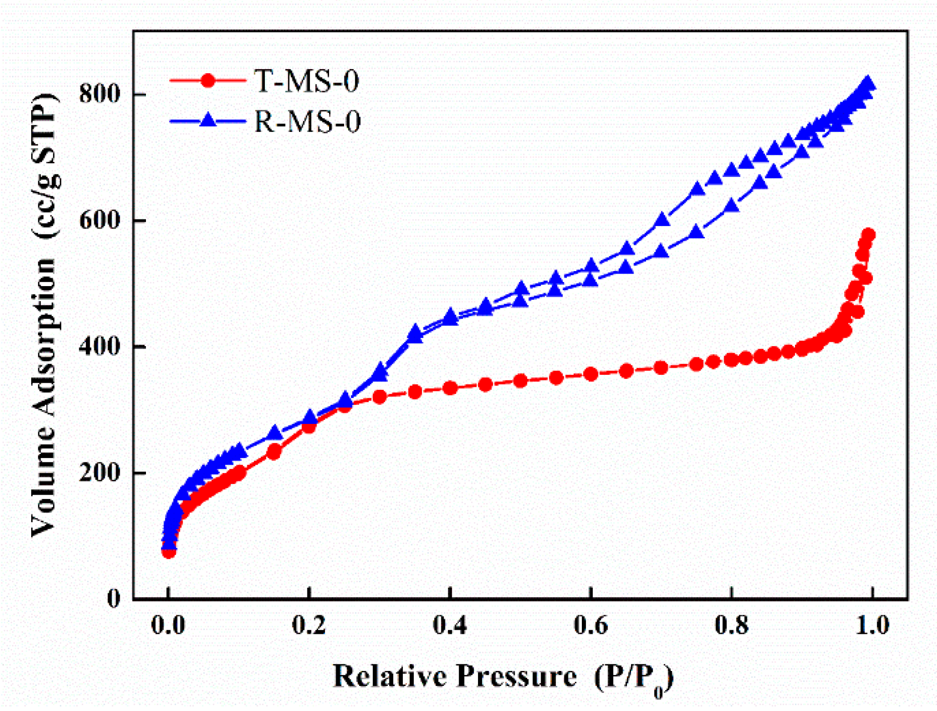
| Sample Name | Surface Area (m2/g) | Pore Volume (cm3/g) | Average Pore Size 1 (nm) |
|---|---|---|---|
| T-MS-0 | 1139.911 | 0.443 | 3.417 |
| R-MS-0 | 1072.455 | 0.845 | 3.058 |
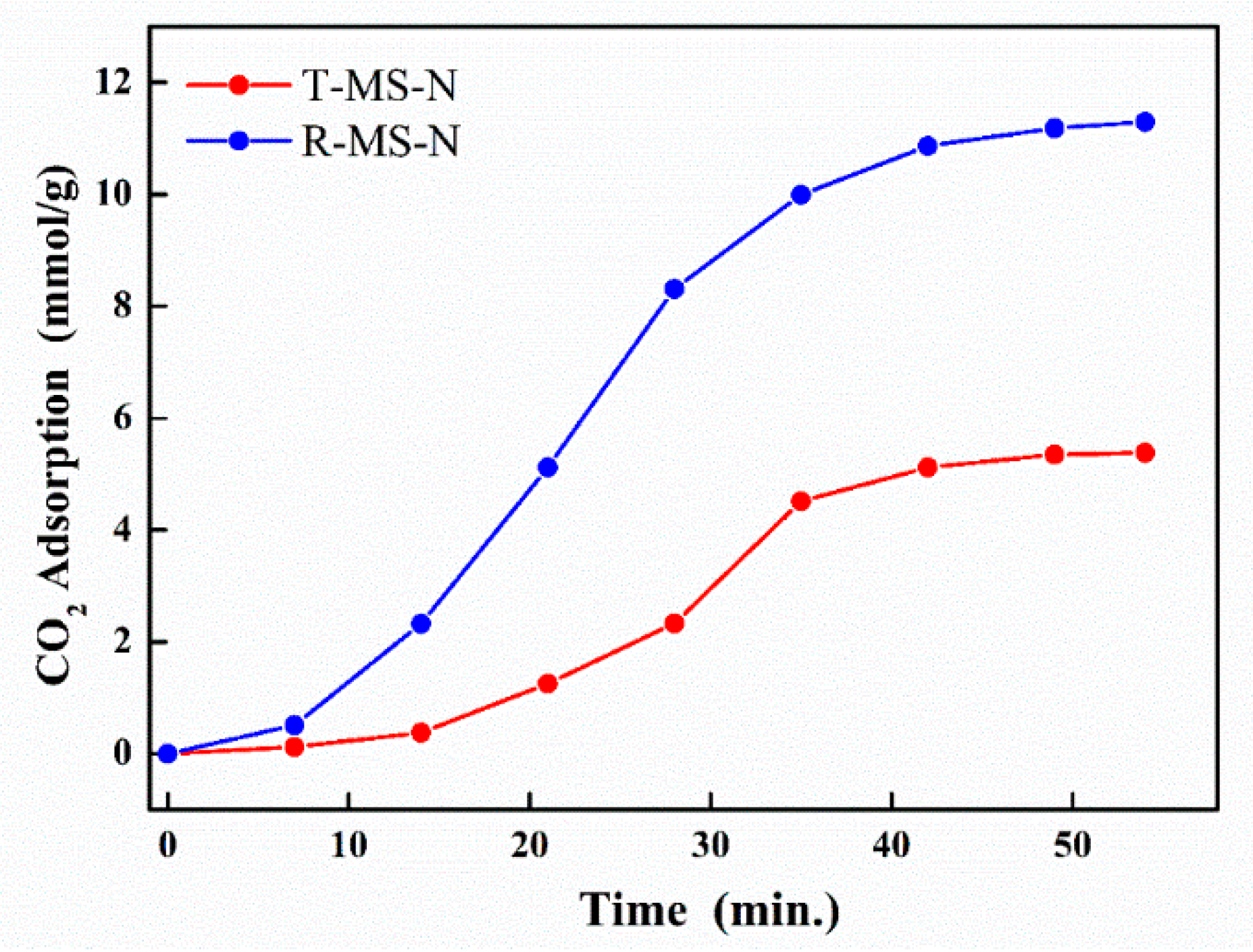
| Sample Name | Pore Volume (cm3/g) | EDS Data | CO2 Adsorption (mmol/g) | Mass Variation after Introducing Amine Functional Groups (g) | ||||
|---|---|---|---|---|---|---|---|---|
| Atom Si (%) | Atom N (%) | Atom C (%) | Atom O (%) | Before | After | |||
| T-MS-N | 0.443 | 6.66 | 18.32 | 49.85 | 25.18 | 5.384 | 0.51 | 1.07 |
| 0.56 | ||||||||
| R-MS-N | 0.845 | 8.65 | 22.98 | 48.06 | 20.31 | 11.296 | 0.49 | 1.07 |
| 0.58 | ||||||||
Publisher’s Note: MDPI stays neutral with regard to jurisdictional claims in published maps and institutional affiliations. |
© 2022 by the authors. Licensee MDPI, Basel, Switzerland. This article is an open access article distributed under the terms and conditions of the Creative Commons Attribution (CC BY) license (https://creativecommons.org/licenses/by/4.0/).
Share and Cite
Kang, M.; Lee, J.-t.; Kim, M.-K.; Byun, M.; Bae, J.-Y. Facile Synthesis of Mesoporous Silica at Room Temperature for CO2 Adsorption. Micromachines 2022, 13, 926. https://doi.org/10.3390/mi13060926
Kang M, Lee J-t, Kim M-K, Byun M, Bae J-Y. Facile Synthesis of Mesoporous Silica at Room Temperature for CO2 Adsorption. Micromachines. 2022; 13(6):926. https://doi.org/10.3390/mi13060926
Chicago/Turabian StyleKang, Misun, Jong-tak Lee, Min-Kyoung Kim, Myunghwan Byun, and Jae-Young Bae. 2022. "Facile Synthesis of Mesoporous Silica at Room Temperature for CO2 Adsorption" Micromachines 13, no. 6: 926. https://doi.org/10.3390/mi13060926