
Visualization and Heat Transfer Performance of Mini-Grooved Flat Heat Pipe Filled with Different Working Fluids


Abstract
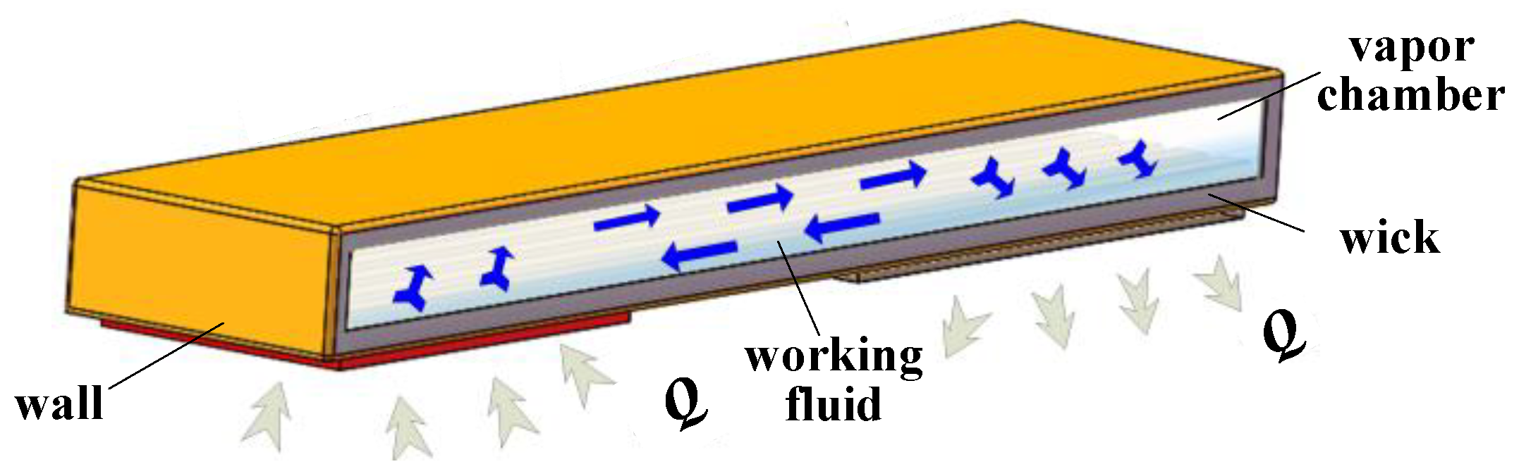
:1. Introduction
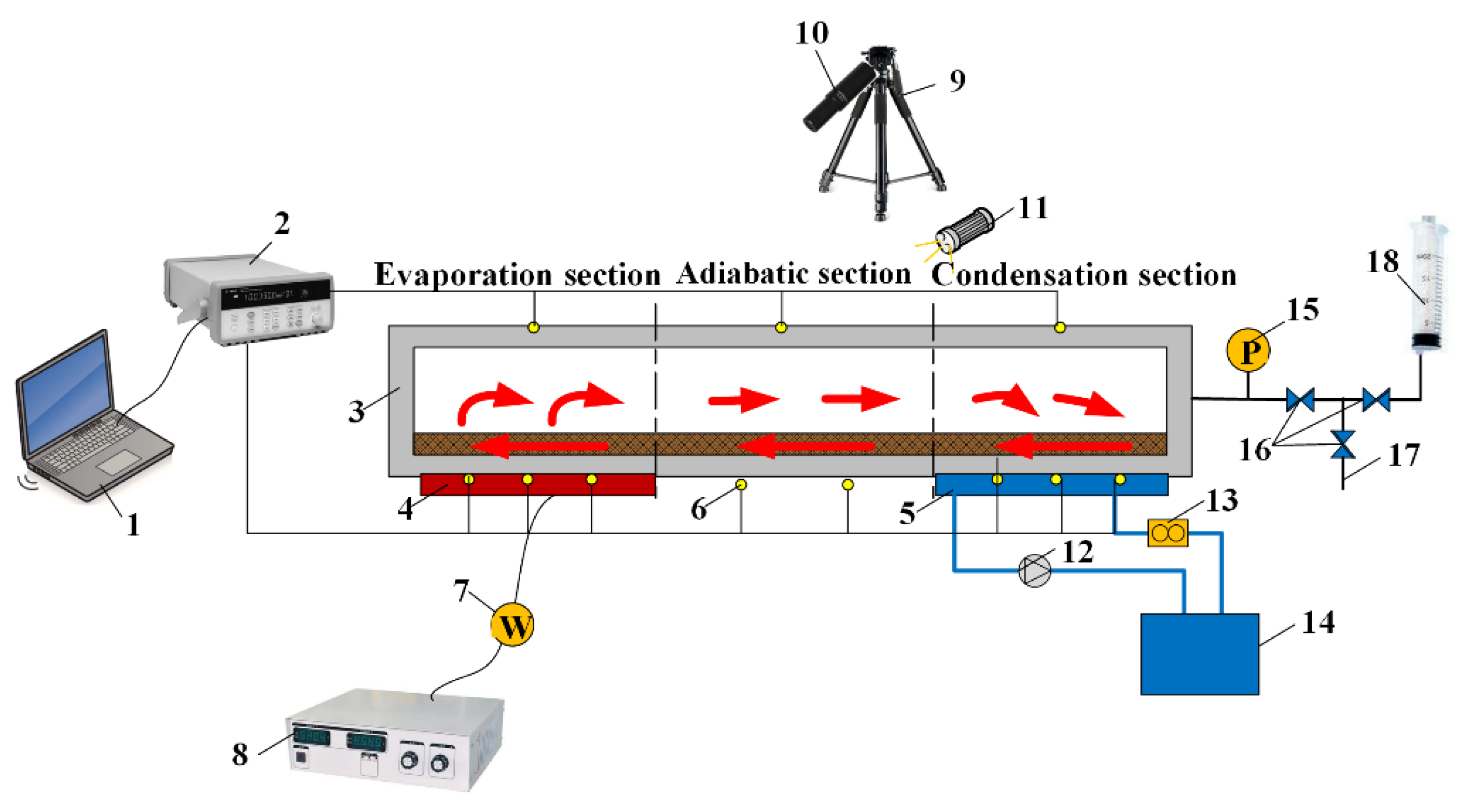
2. Visual and Heat Transfer Experiments Set-Up
3. Results and Discussion
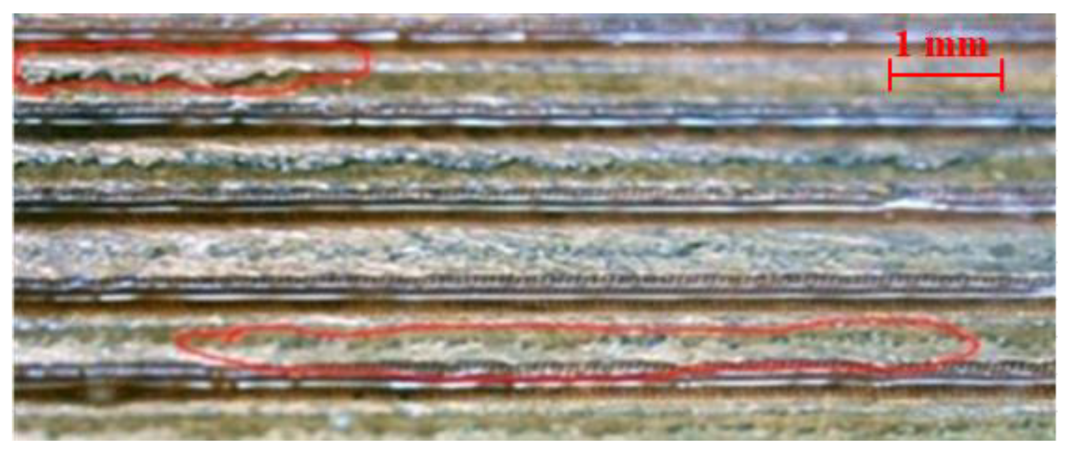
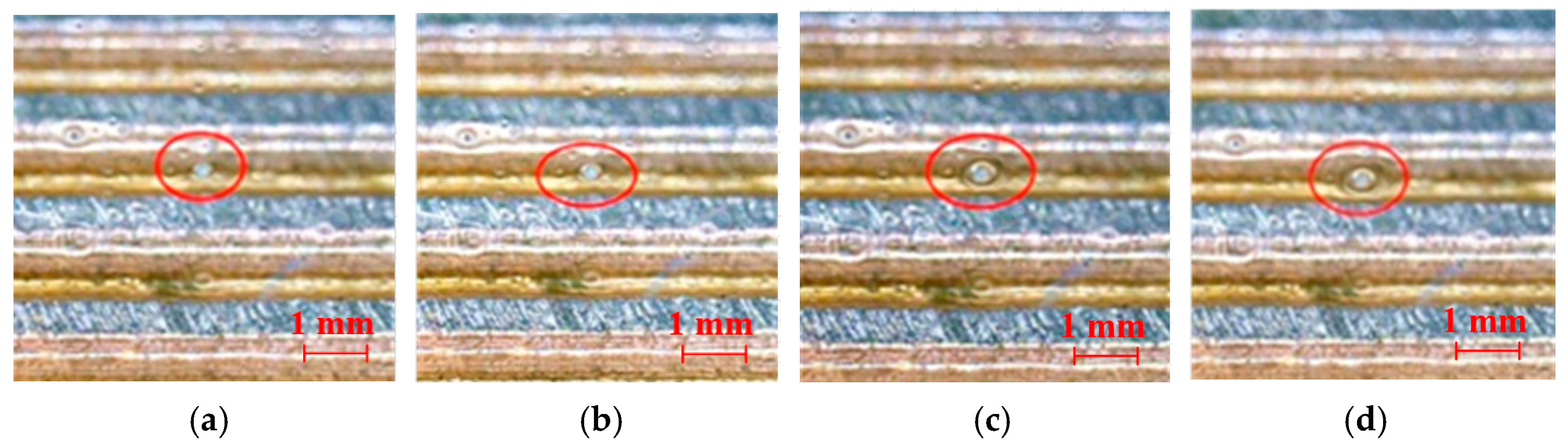
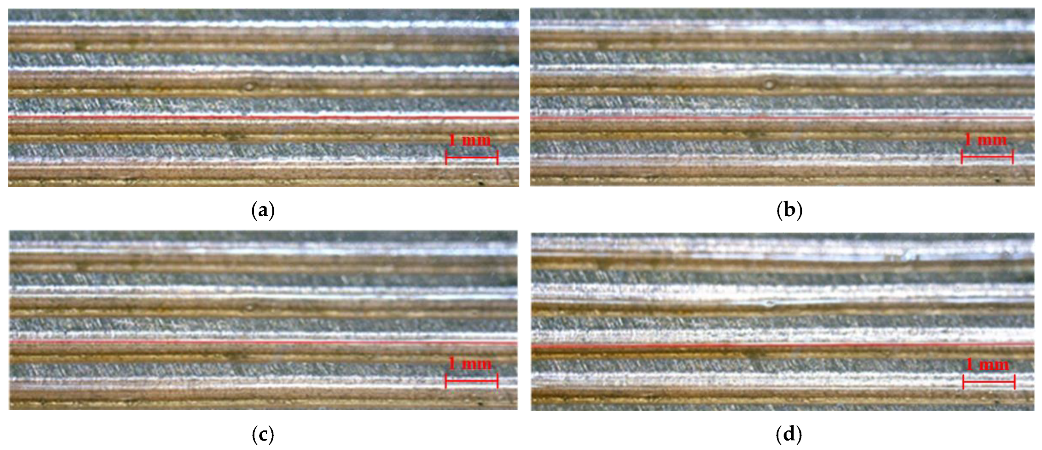
3.1. Visualization Experiment
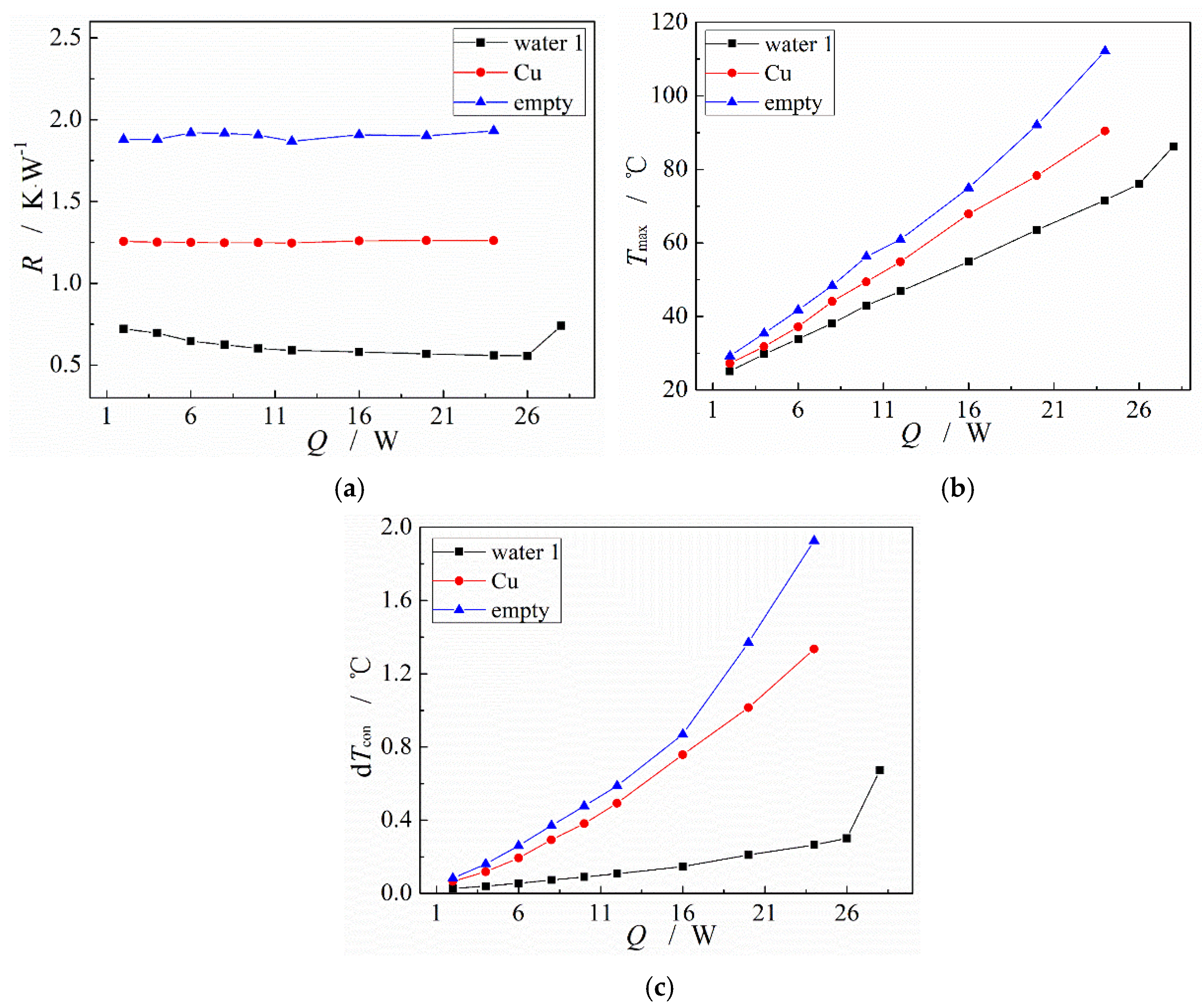
3.2. Comparison of the Heat Transfer Performance between the MGFHP and Copper Plate
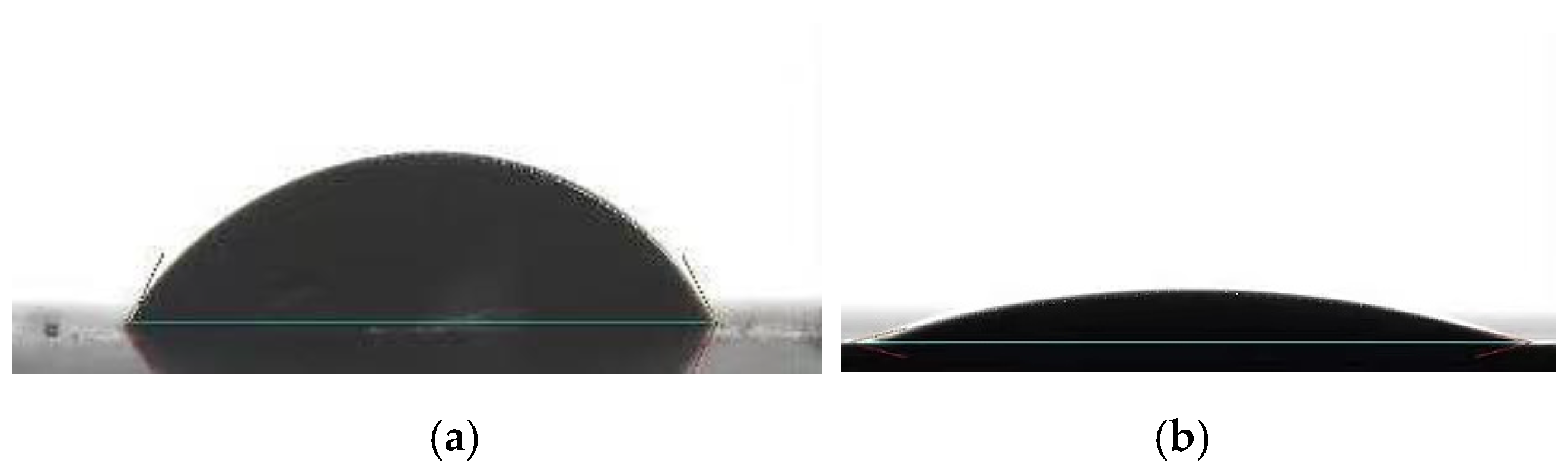
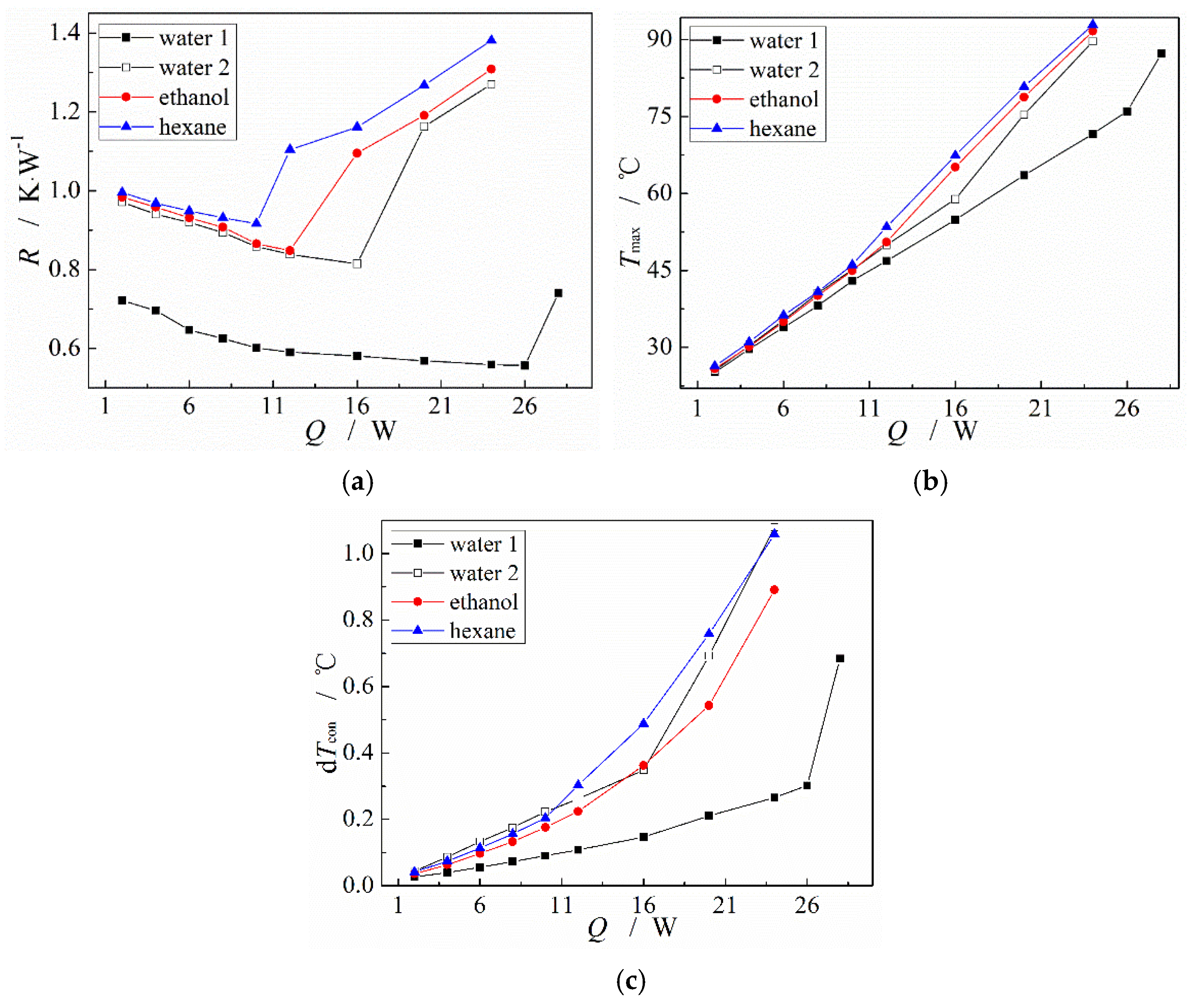
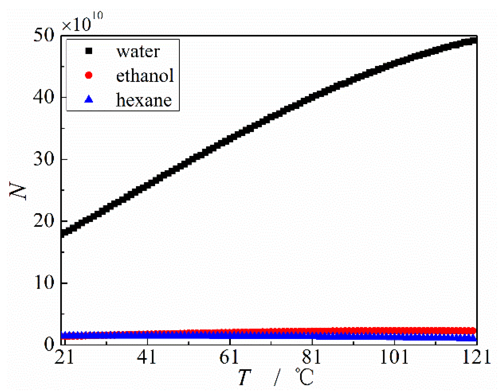
3.3. Influence of Working Fluid Type and Wettability on the MGFHP Performance
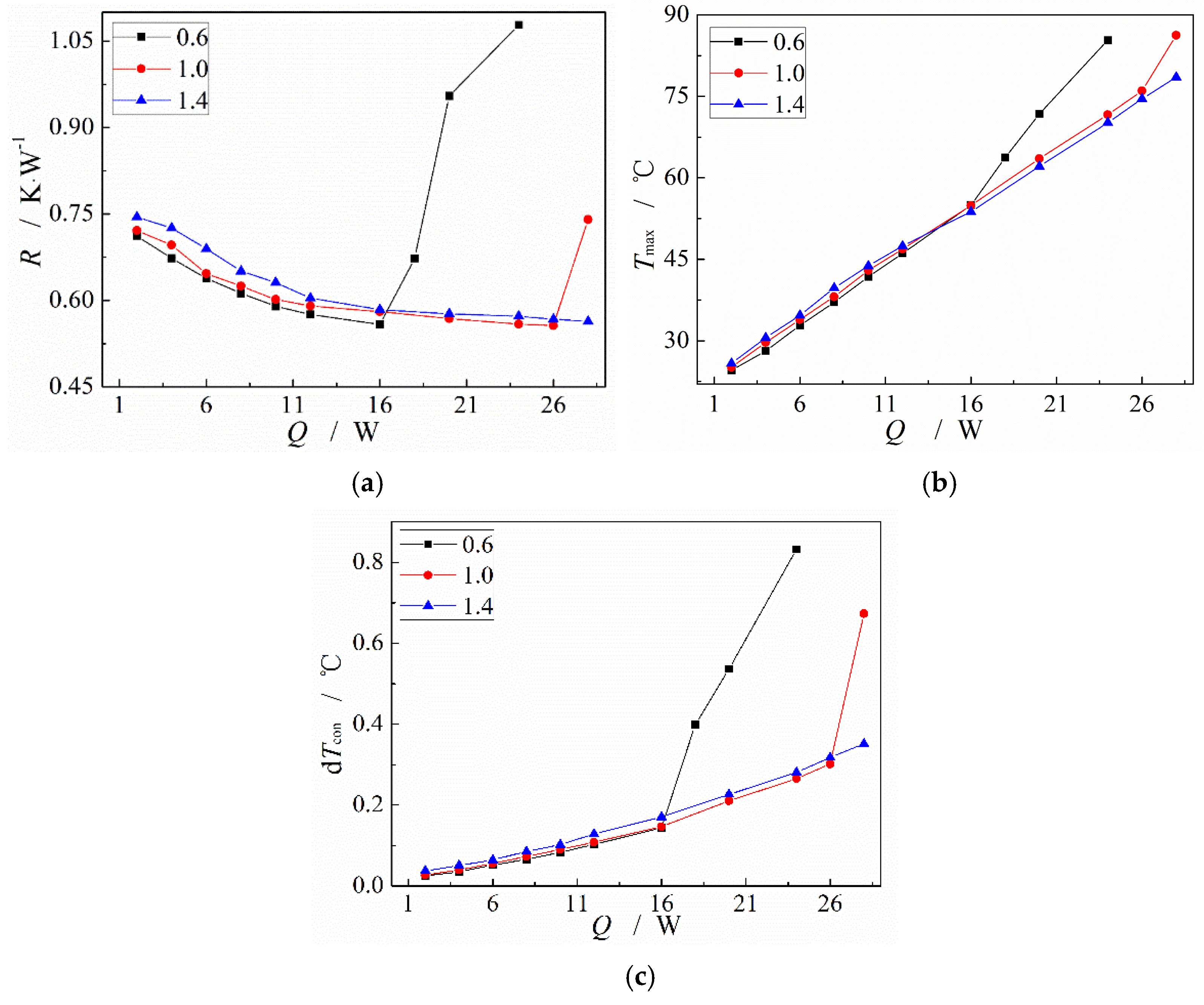
3.4. Influence of Working Fluid Filling Ratio on the MGFHP Performance
4. Conclusions
Author Contributions
Funding
Data Availability Statement
Conflicts of Interest
Nomenclature
| D | relative uncertainty |
| Dt | temperature nonuniformity, °C |
| Gr | Grashof number |
| H | height, m |
| h* | convective heat transfer coefficient, W·m−2·K−1 |
| hfg | latent heat, J·kg−1 |
| l | length, m |
| N | merit factor |
| Nu | Nusselt number |
| Pr | Prandtl number |
| Q | input heat, W |
| Q’ | heat transfer amount, W |
| R | thermal resistance, K·W−1 |
| S | uncertainty |
| S | thickness, m |
| T | temperature, °C |
| average temperature, °C | |
| V | volume, m3 |
| W | width, m |
| Greek symbols | |
| α | half V-type angle value, ° |
| α* | volume expansion coefficient, K−1 |
| η | filling ratio of working fluid |
| λ | thermal conductivity coefficient, W·m−1·K−1 |
| μ | dynamic viscosity coefficient, N·s·m−2 |
| ρ | density, kg·m−3 |
| σ | surface tension, N·m−1 |
| Subscripts | |
| adia | adiabatic |
| ave | average |
| b | boss |
| con | condensation |
| eva | evaporation |
| f | fluid |
| g | groove |
| I | current |
| I | order of number |
| L | liquid |
| Max | maximum |
| Q | input heat |
| Qloss | heat loss |
| R | thermal resistance |
| T | temperature |
| U | voltage |
| V | vapor |
| W | wall |
References
- Khalaj, A.H.; Halgamuge, S.K. A review on efficient thermal management of air-and liquid-cooled data centers: From chip to the cooling system. Appl. Energy 2017, 205, 1165–1188. [Google Scholar] [CrossRef]
- Alijani, H.; Cetin, B.; Akkus, Y.; Dursunkaya, Z. Effect of design and operating parameters on the thermal performance of aluminum flat grooved heat pipes. Appl. Therm. Eng. 2018, 132, 174–187. [Google Scholar] [CrossRef]
- Jung, E.G.; Boo, J.H. A numerical study on the heat and mass transfer of a micro heat pipe with a phase-change interface analysis. Heat Mass Transf. 2017, 53, 3363–3372. [Google Scholar] [CrossRef]
- Qu, J.; Wu, H.; Cheng, P.; Wang, Q.; Sun, Q. Recent advances in MEMs-based micro heat pipes. Int. J. Heat Mass Transf. 2017, 110, 294–313. [Google Scholar] [CrossRef]
- Mihai, I.; Suciu, C.; Picus, C.M. Considerations for the maximum heat load and its influence on temperature variation of the evaporator in flat MHPs in transient regimes. Micromachines 2022, 13, 979. [Google Scholar] [CrossRef]
- Li, J.; Lv, L.; Zhou, G.; Li, X. Mechanism of a microscale flat plate heat pipe with extremely high nominal thermal conductivity for cooling high-end smartphone chips. Energy Convers. Manag. 2019, 201, 112202. [Google Scholar] [CrossRef]
- Liang, K.; Li, Z.; Chen, M.; Jiang, H. Comparisons between heat pipe, thermoelectric system, and vapour compression refrigeration system for electronics cooling. Appl. Therm. Eng. 2019, 146, 260–267. [Google Scholar] [CrossRef]
- Lu, M.C. Exploring the Limits of Boiling and Evaporative Heat Transfer Using Micro/Nano Structures. Ph.D. Thesis, University of California, Berkeley, CA, USA, 2010. [Google Scholar]
- Lips, S. Contribution to the Experimental and Theoretical Study of Phase-Change Heat Transfer for the Thermal Management of Electronics. Ph.D. Thesis, Université Claude Bernard Lyon, Villeurbanne, French, 2018. [Google Scholar]
- Morris, S.J.S. The evaporating meniscus in a channel. J. Fluid Mech. 2003, 494, 297–317. [Google Scholar] [CrossRef]
- Singh, R.; Akbarzadeh, A.; Mochizuki, M. Effect of wick characteristics on the thermal performance of the miniature loop heat pipes. ASME J. Heat Transf. 2009, 131, 082601. [Google Scholar] [CrossRef]
- Tang, H.; Tang, Y.; Li, J.; Sun, Y.; Liang, G.; Peng, R. Experimental investigation of the thermal performance of heat pipe with multi-heat source and double-end cooling. Appl. Therm. Eng. 2018, 131, 159–166. [Google Scholar] [CrossRef]
- Alijani, H.; Cetin, B.; Akkus, Y.; Dursunkaya, Z. Experimental thermal performance characterization of flat grooved heat pipes. Heat Transf. Eng. 2019, 40, 784–793. [Google Scholar] [CrossRef]
- Lips, S.; Lefèvre, F.; Bonjour, J. Nucleate boiling in a flat grooved heat pipe. Int. J. Therm. Sci. 2009, 48, 1273–1278. [Google Scholar] [CrossRef]
- Wang, C.; Liu, Z.; Zhang, G. Experimental investigations of flat plate heat pipes with interlaced narrow grooves or channels as capillary structure. Exp. Therm. Fluid Sci. 2013, 48, 222–229. [Google Scholar] [CrossRef]
- Chen, J.S.; Chou, J.H. Cooling performance of flat plate heat pipes with different liquid filling ratios. Int. J. Heat Mass Transf. 2014, 77, 874–882. [Google Scholar] [CrossRef]
- Wang, G.; Quan, Z.; Zhao, Y.; Wang, H. Performance of a flat-plate micro heat pipe at different filling ratios and working fluids. Appl. Therm. Eng. 2019, 146, 459–468. [Google Scholar] [CrossRef]
- Saygan, S.; Akkus, Y.; Dursunkaya, Z.; Cetin, B. Capillary boosting for enhanced heat pipe performance through bifurcation of grooves: Numerical assessment and experimental validation. Int. Commun. Heat Mass 2022, 137, 106162. [Google Scholar] [CrossRef]
- Saygan, S.; Akkus, Y.; Dursunkaya, Z.; Cetin, B. Fast and predictive heat pipe design and analysis toolbox: H-PAT. Isi Bilimi Ve Tek. Derg. J. Therm. Sci. Technol. 2022, 42, 141–156. [Google Scholar] [CrossRef]
- Wong, S.C.; Chen, C.W. Visualization and evaporator resistance measurement for a groove-wicked flat-plate heat pipe. Int. J. Heat Mass Transf. 2012, 55, 2229–2234. [Google Scholar] [CrossRef]
- Tio, K.K.; Hung, Y.M. Analysis of overloaded micro heat pipes: Effects of solid thermal conductivity. Int. J. Heat Mass Transf. 2015, 81, 737–749. [Google Scholar] [CrossRef]
- Zhang, W.; Wen, X.; Yang, S.; Berta, Y.; Wang, Z.L. Single-crystalline scroll-type nanotube arrays of copper hydroxide synthesized at room temperature. Adv. Mater. 2003, 15, 822–825. [Google Scholar] [CrossRef]
- Iverson, B.D.; Davis, T.W.; Garimella, S.V.; North, M.T.; Kang, S.S. Heat and mass transport in heat pipe wick structures. J. Thermophys. Heat Transf. 2007, 21, 392–404. [Google Scholar] [CrossRef]
- Liu, C.; Chen, Y.; Feng, D.; Zhang, H.; Miao, J.; Feng, Y.; Yan, Y.; Zhang, X. Experimental study on temperature uniformity and heat transfer performance of nitrogen loop heat pipe with large area and multi-heat source. Appl. Therm. Eng. 2022, 210, 118344. [Google Scholar] [CrossRef]
- Solomon, A.B.; Kumar, A.M.R.; Ramachandran, K.; Pillai, B.C.; Kumar, C.S.; Sharifpur, M.; Meyer, J.P. Characterization of a grooved heat pipe with an anodised surface. Heat Mass Transf. 2017, 53, 753–763. [Google Scholar] [CrossRef]
- Liao, X.; Jian, Q.; Zu, S.; Li, D.; Huang, Z. Visualization study and analysis on the heat transfer performance of an ultra-thin flat-plate heat pipe. Int. Commun. Heat Mass 2021, 126, 105464. [Google Scholar] [CrossRef]
- Faghri, A. Heat Pipe Science and Technology; Taylor & Francis: Washington, DC, USA, 1995. [Google Scholar]
- Rag, R.; Sobhan, C. Computational analysis of fluid flow and heat transfer in wire-sandwiched microheat pipes. J. Thermophys. Heat Transf. 2009, 23, 741–751. [Google Scholar] [CrossRef]
- Carey, V.P. Liquid-Vapor Phase-Change Phenomena; Taylor &Francis: Washington, DC, USA, 2007. [Google Scholar]
- Xin, F.; Ma, T.; Wang, Q. Thermal performance analysis of flat heat pipe with graded mini-grooves wick. Appl. Energy 2018, 228, 2129–2139. [Google Scholar] [CrossRef]
- Oshman, C.; Shi, B.; Li, C.; Yang, R.; Lee, Y.C.; Peterson, G.P.; Bright, V.M. The development of polymer-based flat heat pipes. J. Microelectromech. Syst. 2011, 20, 410–417. [Google Scholar] [CrossRef]
- Jiao, A.J.; Ma, H.B.; Critser, J.K. Evaporation heat transfer characteristics of a grooved heat pipe with micro-trapezoidal grooves. Int. J. Heat Mass Transf. 2007, 50, 2905–2911. [Google Scholar] [CrossRef]
- Li, J.; Lv, L. Experimental studies on a novel thin flat heat pipe heat spreader. Appl. Therm. Eng. 2016, 93, 139–146. [Google Scholar] [CrossRef]
- Patankar, G.; Weibel, J.A.; Garimella, S.V. Working-fluid selection for minimized thermal resistance in ultra-thin vapor chambers. Int. J. Heat Mass Transf. 2017, 106, 648–654. [Google Scholar] [CrossRef]
- Peng, Y.; Liu, W.; Liu, B.; Liu, J.; Huang, K.; Wang, L.; Chen, W. The performance of the novel vapor chamber based on the leaf vein system. Int. J. Heat Mass Transf. 2015, 86, 656–666. [Google Scholar] [CrossRef]
- Rice, J.; Faghri, A. Analysis of porous wick heat pipes, including capillary dry-out limitations. In Proceedings of the ASME 2005 International Mechanical Engineering Congress and Exposition, Orlando, FL, USA, 5–11 November 2005. [Google Scholar]


| Parameter | wv (mm) | hv (mm) | wg (mm) | wb (mm) | hg (mm) | s1 (mm) | leva (mm) | ladia (mm) | lcon (mm) | s2 (mm) | s3 (mm) | α (°) |
|---|---|---|---|---|---|---|---|---|---|---|---|---|
| value | 20.0 | 2.0 | 0.8 | 0.8 | 0.8 | 0.7 | 20.0 | 20.0 | 40.0 | 1.5 | 1.0 | 26.6 |
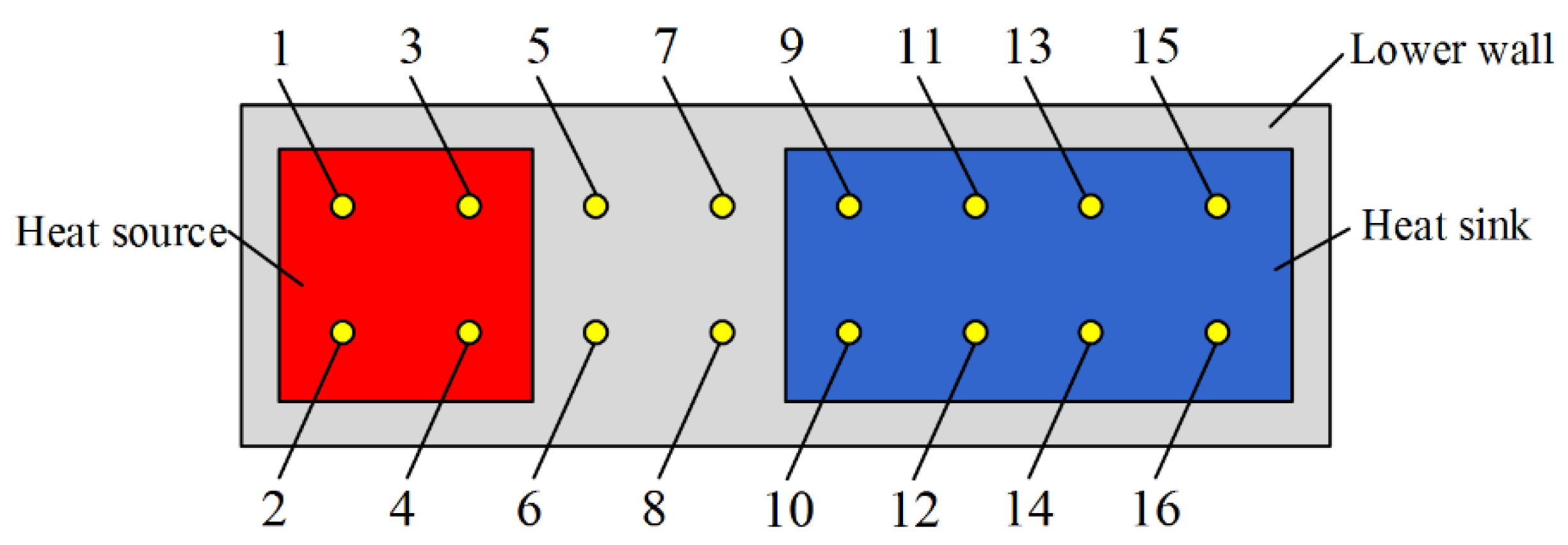
| Number | Location | Function |
|---|---|---|
| 1–16 | bottom surface of the MGFHP | calculate the heat transfer performance of the MGFHP |
| 17 | air temperature | measure the environment temperature |
| 18–22 | lower surfaces at evaporation, adiabatic, condensation sections, and upper surfaces of evaporation, adiabatic sections outside the insulation cotton of the MGFHP | calculate the heat loss in the MGFHP |
| Thermocouple Number | 17 | 18 | 19 | 20 | 21 | 22 |
|---|---|---|---|---|---|---|
| Temperature (°C) | 24.6 | 58.2 | 46.5 | 46.7 | 42.6 | 38.4 |
| Corresponding Heat Loss (W) | / | 0.148 | 0.087 | 0.088 | 0.068 | 0.083 |
Publisher’s Note: MDPI stays neutral with regard to jurisdictional claims in published maps and institutional affiliations. |
© 2022 by the authors. Licensee MDPI, Basel, Switzerland. This article is an open access article distributed under the terms and conditions of the Creative Commons Attribution (CC BY) license (https://creativecommons.org/licenses/by/4.0/).
Share and Cite
Xin, F.; Lyu, Q.; Tian, W. Visualization and Heat Transfer Performance of Mini-Grooved Flat Heat Pipe Filled with Different Working Fluids. Micromachines 2022, 13, 1341. https://doi.org/10.3390/mi13081341
Xin F, Lyu Q, Tian W. Visualization and Heat Transfer Performance of Mini-Grooved Flat Heat Pipe Filled with Different Working Fluids. Micromachines. 2022; 13(8):1341. https://doi.org/10.3390/mi13081341
Chicago/Turabian StyleXin, Fei, Qiang Lyu, and Wenchao Tian. 2022. "Visualization and Heat Transfer Performance of Mini-Grooved Flat Heat Pipe Filled with Different Working Fluids" Micromachines 13, no. 8: 1341. https://doi.org/10.3390/mi13081341
APA StyleXin, F., Lyu, Q., & Tian, W. (2022). Visualization and Heat Transfer Performance of Mini-Grooved Flat Heat Pipe Filled with Different Working Fluids. Micromachines, 13(8), 1341. https://doi.org/10.3390/mi13081341