Article

Ultra-Smooth and Efficient NiO/Ag/NiO Transparent Electrodes for Flexible Organic Light-Emitting Devices

1
School of Electronic Information Engineering, Changchun University of Science and Technology, Changchun 130022, China
2
School of Physics, Changchun University of Science and Technology, Changchun 130022, China
*
Author to whom correspondence should be addressed.
Micromachines 2022, 13(9), 1511; https://doi.org/10.3390/mi13091511
Submission received: 29 August 2022 / Revised: 7 September 2022 / Accepted: 9 September 2022 / Published: 12 September 2022
(This article belongs to the Special Issue Organic Light Emitting Diodes (OLEDs))

Abstract

:
We demonstrate highly flexible and efficient organic light-emitting devices (OLEDs) using an ultra-smooth NAN anode. A template-stripping process was employed to create an ultra-smooth NAN anode on a photopolymer substrate. The flexible OLEDs obtained by this method maintained good electroluminescent properties and mechanical stability after bending. The efficiency of the flexible OLEDs was improved by 30.6% compared with conventional OLEDs deposited on PET/ITO substrate due to the enhanced hole injection from the ultra-smooth anode.

1. Introduction

In recent years, transparent conductive films have been used as electrodes in a variety of optoelectronic devices, such as liquid crystal display (LCD), organic light-emitting diodes (OLEDs), and solar cells. Earlier transparent conductive materials were oxides. Since the 1960s, indium tin oxide (ITO) has become the most representative transparent conductive material and is widely used [1,2,3,4]. It has a sheet resistance in the range of 20–500 Ω/□, and it boasts some significant advantages, such as high visible light transmittance and mature preparation technology [5]. However, it also has clear disadvantages; for instance, it is fairly “brittle” and, therefore, is not suitable for flexible OLEDs.
There are several alternatives that have been reported for ITO, such as carbon nanotubes [6,7,8,9], conducting polymers [10,11,12], graphene [13,14,15,16], metallic nanowires [17,18,19], and metallic grids [20,21,22]. However, many of these alternative materials suffer from either large sheet resistance [9,14] or high surface roughness [17,18,19,20], which cause low hole injection and reduced efficiency for OLEDs. Therefore, novel transparent electrodes with good optoelectrical properties and mechanical flexibility with low cost and low-temperature processing remain a big challenge.
Since the 1950s, research has shown that, if metal layers are placed into proper dielectric layers to form laminated constructions, the transmittance of the metal layers can be effectively enhanced [23,24]. Moreover, compared with the single-layer insertion of transparent conductive oxide films, laminated transparent conductive films yield a series of advantages, such as lower resistivity, near-room-temperature preparation technology, lower cost, good machinability, suppleness, and design flexibility. As such, research on dielectric−metal−dielectric (DMD) conductive film has gained traction in recent years [25]. However, for a usual flexible substrate, if DMD electric films are directly deposited on it, the high temperature of the deposition damages the substrate, and the deposited dielectric films are rough.
In this article, a nickel oxide (NiO)/silver (Ag)/nickel oxide (NiO) film with an ultra-smooth surface morphology is fabricated on a plastic substrate by employing a template-stripping technique and is used as an anode in flexible OLEDs. The NiO/Ag/NiO (NAN) OLEDs show superiority in both flexibility and mechanical stability. Moreover, the efficiency is 30.6% enhanced compared with conventional ITO OLEDs due to the enhanced hole injection at the ultra-smooth NAN–organic interface.

2. Materials and Methods

The NAN films were deposited on a precleaned, polished Si substrate by electron beam evaporation at room temperature. The evaporation rates of NiO and Ag were 0.09–0.11 and 0.9–1.1 nm/s, respectively, at pressures below 2.0 × 10⁻³ Pa. The hole-only devices and OLEDs were fabricated by thermal evaporation at room temperature. The evaporation rates of the organic material and Al were 0.1–0.2 and 0.9–1.1 nm/s, respectively, at pressures below 5.0 × 10⁻⁴ Pa. The active areas of the devices were all 1 × 1 mm2. The sheet resistance was measured using a four-probe method. An HMS-3000 Hall effect measurement system was used to measure the carrier concentration and Hall mobility of the NAN films, with an applied magnetic field of 0.55 T. A KP Technology Ambient Kelvin probe system package was used to measure the surface work function of the NAN films. A Shimadzu SPM-9700 was used to capture the AFM pictures. The J–V characteristics of the hole-only devices and OLEDs were measured using a computer-controlled Keithley 2611 source meter. The luminance of the OLEDs was measured using a Konica Minolta CS-100A luminance meter. The electroluminescent (EL) emission spectra were recorded using an Ocean Optics fiber spectrometer. The measurements were all conducted in air at room temperature.

3. Results and Discussion

The transmittance in the visible range is an important parameter for transparent conductive films as anodes for OLEDs. If the Ag layer in NAN films is too thin, its conductivity is compromised, and if it is too thick, the transmittance is not good. Previous experiments have pointed to an Ag thickness of 11 nm as the best balance between conductivity and transmittance. After determining the thickness of the Ag, we performed optical simulations for different thicknesses of the NiO layers as they were combined with the Ag, as shown in Figure 1. We can see that, when both NiO layers were at 35 nm of thickness, the NAN film had a high average transmittance in the wavelength of 380 nm–780 nm. Therefore, we adopted a NiO (35 nm)/Ag (11 nm)/NiO (35 nm) structure for the NAN thin film in this article, and its transmittance was above 80% in the green band.
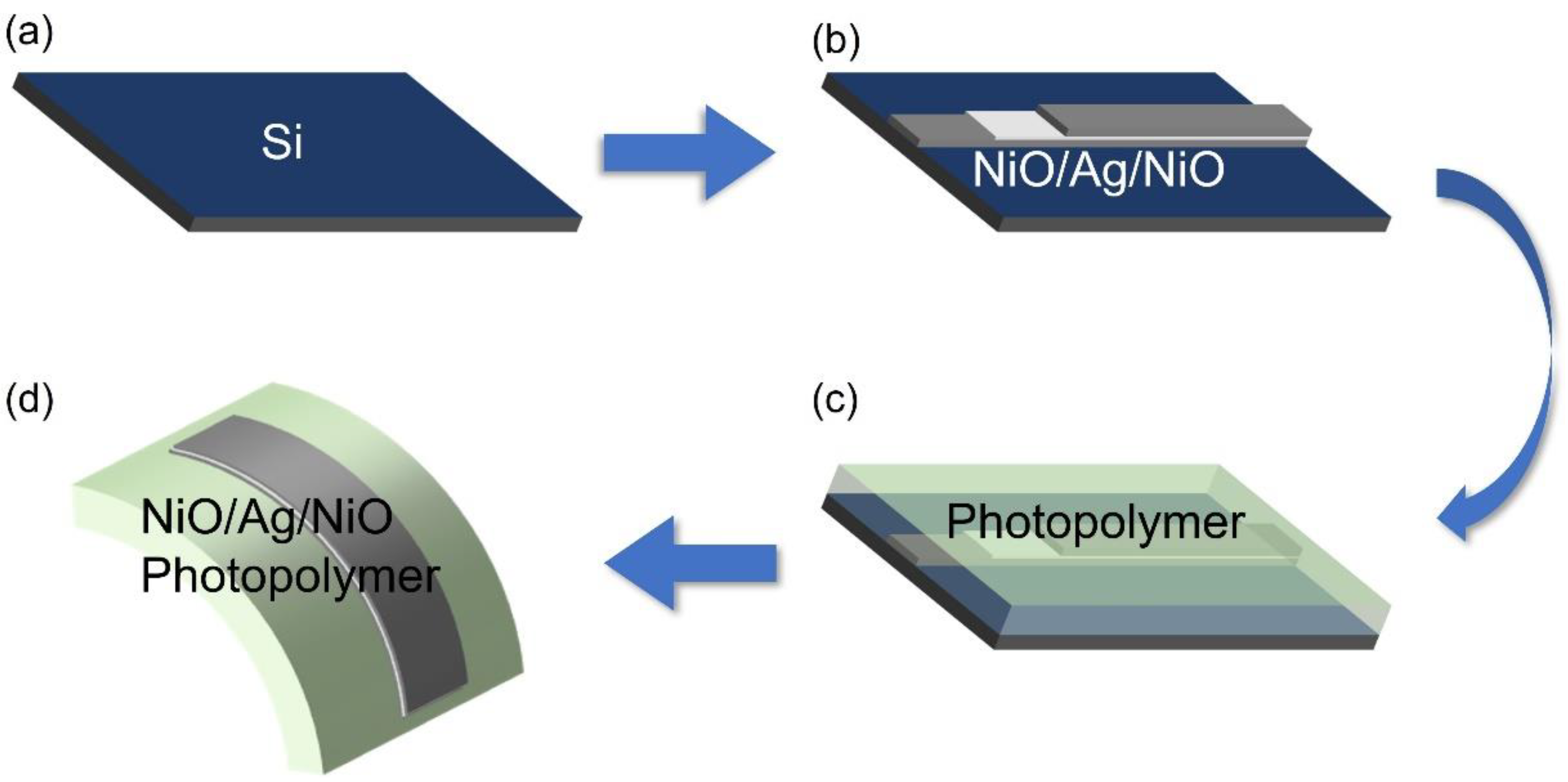
We adopted a stripping technique to fabricate the ultra-smooth NAN thin film, as shown in Figure 2. First, a cleaned silicon (Si) template was loaded into an electron beam evaporation chamber. An 81 nm thick NAN film was grown on the Si template. Then, a 1 mm thick photopolymer (NOA63, Norland) was spin-coated on the NAN film at 1000 rpm for 20 s. After that, the photoresist was solidified with ultraviolet light under a 100 w light source for 8 min. Lastly, the cured photoresist was stripped off the silicon wafer. Because the adhesion between NiO and Ag, as well as between NiO and the photoresist, was stronger than that between NiO and Si, the NAN film could be stripped off the silicon wafer. With this stripping technique, an ultra-smooth NAN flexible substrate was obtained, and the process could be repeated decently in a large area.
PET/ITO is a currently popular flexible transparent anode. We, therefore, compared the surface roughness (RMS) of the ultra-smooth Photopolymer/NAN with PET/ITO. Figure 3 shows AFM images of the surface roughness of Photopolymer/NAN and PET/ITO. It was observed that, in the scanned area of 2 μm × 2 μm, the average surface roughness (RMS) values of PET/ITO and Photopolymer/NAN were 2.52 nm and 1.73 nm, respectively. The average roughness (Ra) values of PET/ITO and Photopolymer/NAN were 2.06 nm and 1.26 nm, respectively. Because ITO film is grown directly on a PET surface, it is riddled with studs and, therefore, is very rough, whereas on NAN films, studs only pop up occasionally and sparingly and are very scattered, rather than concentrated on the film surface. Therefore, in general, the NAN film could be categorized as an ultra-smooth film. We also measured the work function, carrier density, and Hall mobility of the NAN film. The work function was 5.3 eV, the carrier density was 8.559 × 1021 cm−3, and the Hall mobility was 14.23 cm2/Vs. A calculated sheet resistance of 7.6 Ω/□ was achieved, which was lower than those of most commercial ITO electrodes [26].
The data above show that the carrier density and carrier mobility of the NAN film were like those of ITO, yet its work function (5.3 eV) was significantly higher than that of ITO (4.7 eV). Take the most common hole transport material, N,N′-diphenyl-N,N″-bis(1,1′-biphenyl)-4,4′-diamine (NPB), as an example: its HOMO level is 5.4 eV. That means, if we used NAN film as an anode, because its work function was nearly at the HOMO level of NPB, it would provide an edge for the hole to be injected into the anode. Furthermore, because the hole now needed to jump a smaller energy level difference, there was no need to add a hole injection layer between the anode and the hole transport layer. This would greatly reduce the fabrication complexity of OLED devices.
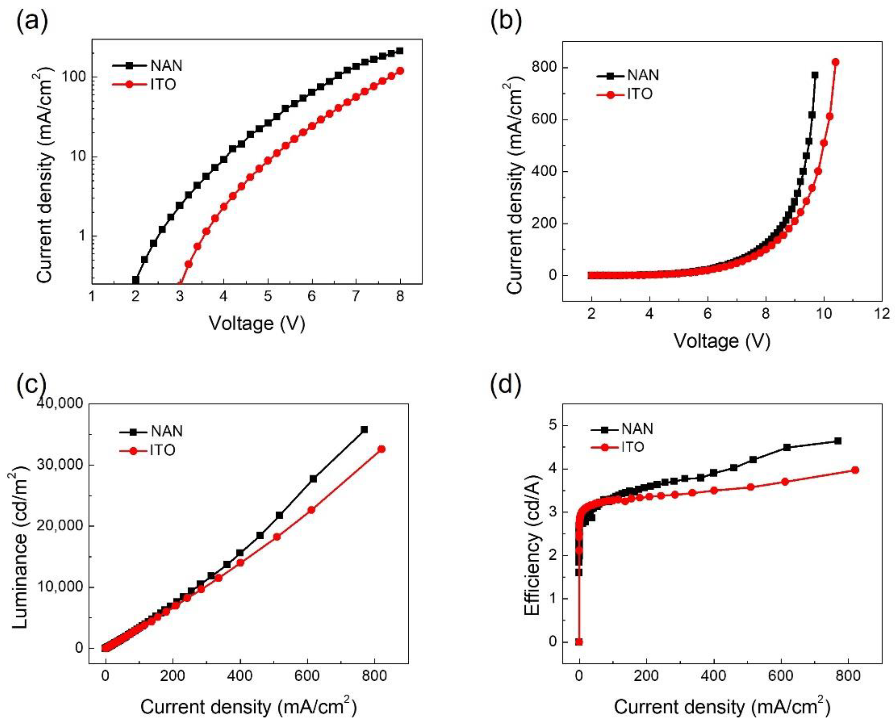
To demonstrate the hole injection capacity of the NAN ultra-smooth film, we fabricated two types of hole-only devices. Their structures were NAN/NPB (60 nm)/Al (100 nm) and ITO/NPB (60 nm)/Al (100 nm). In the two devices, the roles of the NPB were hole injection and transport layer. Because the work function of Al was 4.2 eV and the LUMO level of NPB was 2.4 eV, a huge transition barrier was created for the electrons so that it was very difficult for them to be injected from the cathode. Figure 4a shows the voltage–current density curve of the hole-only device. The current density of the NAN film anode hole-only device was greater than that of the ITO anode hole-only device. This shows that the ultra-smooth NAN film was very conducive to enhancing the hole injection efficiency.
We then used the ultra-smooth NAN film and the PET/ITO as anodes and fabricated two types of OLEDs. Tris-(8-hydroxyquinoline) aluminum (Alq3) was used as an emitting layer. The device structures were NAN/NPB (60 nm)/Alq3 (70 nm)/LiF (1 nm)/Al (100 nm) and ITO/NPB (60 nm)/Alq3 (70 nm)/LiF (1 nm)/Al (100 nm). Figure 3b–d compares the performance curves of the NAN-anode-based and ITO-anode-based OLEDs. The maximum efficiency of the NAN-anode-based OLED was 4.7 cd/A, whereas that of the ITO-anode-based OLED was 3.6 cd/A; that was a 30.6% enhancement in efficiency. Such an enhancement came from the greater work function and the smaller surface roughness of the NAN film, both contributing to a higher hole injection efficiency.
A bending test was conducted on the NAN-anode-based OLED. We bent it into a U shape, almost folding it. Figure 5 shows the luminosity, efficiency, and luminescence spectrum of the device after repeated bending and at a voltage of 8 V. It can be observed that, after 0–100 times of bending, the luminosity and efficiency of the device did not change much. Moreover, the luminescence spectrum did not move much, demonstrating the good mechanical stability of this ultra-smooth NAN film.

4. Conclusions

In conclusion, an ultra-smooth flexible NAN film was prepared using a stripping technique. It was then used as an anode in the fabrication of a flexible OLED. Because the NAN had a higher work function and smoother surface compared to ITO, it enhanced the hole injection efficiency and, therefore, the luminosity and efficiency of the OLED. Furthermore, bending tests demonstrated the strong mechanical stability of the NAN anode made with the stripping technique. This research showed that films prepared using such stripping and lamination methods could be good candidates for anodes in indium-free, flexible OLEDs in a large-scale fabrication context.

Author Contributions

Software, Y.C.; validation, Y.W. (Yingzhi Wang); writing—original draft, Y.B.; writing—review and editing, Y.W. (Yang Wang) All authors have read and agreed to the published version of the manuscript.

Funding

This research was funded by the Jilin Province Science and Technology Development Project (20210101182JC and YDZJ202201ZYTS297), the Education Department of Jilin Province (JJKH20200754KJ), the Jilin Inter-Regional Cooperation Center for the Scientific and Technological Innovation (20200602005ZP), and the National Natural Science Foundation of China (62204024).

Data Availability Statement

Not applicable.

Conflicts of Interest

The authors declare that they do not have any competing financial interests or personal relationships that could have appeared to influence the work reported in this paper.

References

  1. Morales-Masis, M.; Wolf, S.D.; Woods-Robinson, R.; Ager, J.W.; Ballif, C. Transparent electrodes for efficient optoelectronics. Adv. Electron. Mater. 2017, 3, 1600529. [Google Scholar] [CrossRef]
  2. Tran, V.H.; Khan, R.; Lee, I.H. Low-temperature solution-processed ionic liquid modified SnO2 as an excellent electron transport layer for inverted organic solar cells. Solar Energy Mater. Solar Cells 2017, 179, 260–269. [Google Scholar] [CrossRef]
  3. Lim, C.; Bae, S.; Jeong, S.M.; Ha, N.Y. Manipulation of Structural Colors in Liquid-Crystal Helical Structures Deformed by Surface Controls. ACS Appl. Mater. Interfaces 2018, 10, 12060–12065. [Google Scholar] [CrossRef]
  4. Yu, S.H.; Jia, C.H.; Zheng, H.W.; Ding, L.H.; Zhang, W.F. High quality transparent conductive SnO2/Ag/SnO2 tri-layer films deposited at room temperature by magnetron sputtering. Mater. Lett. 2012, 85, 68–70. [Google Scholar] [CrossRef]
  5. Hutter, O.S.; Stec, H.M.; Hatton, R.A. An indium-free low work function window electrode for organic photovoltaics which improves with in-situ oxidation. Adv. Mater. 2013, 25, 284–288. [Google Scholar] [CrossRef]
  6. Wu, Z.; Chen, Z.; Du, X.; Logan, J.M.; Sippel, J.; Nikolou, M.; Kamaras, K.; Reynolds, J.R.; Tanner, D.B.; Hebard, A.F.; et al. Transparent, Conductive Carbon Nanotube Films. Science 2004, 305, 1273–1276. [Google Scholar] [CrossRef] [PubMed]
  7. Tenent, R.C.; Barnes, T.M.; Bergeson, J.D.; Ferguson, A.J.; To, B.; Gedvilas, L.M.; Heben, M.J.; Blackburn, J.L. Ultrasmooth, LargeArea, High-Uniformity, Conductive Transparent Single-Walled-Carbon-Nanotube Films for Photovoltaics Produced by Ultrasonic Spraying. Adv. Mater. 2009, 21, 3210–3216. [Google Scholar] [CrossRef]
  8. Barnes, T.M.; Reese, M.O.; Bergeson, J.D.; Larsen, B.A.; Blackburn, J.L.; Beard, M.C.; Bult, J.; Lagemaat, J. Comparing the Fundamental Physics and Device Performance of Transparent, Conductive Nanostructured Networks with Conventional Transparent Conducting Oxides. Adv. Energy Mater. 2012, 2, 353–360. [Google Scholar] [CrossRef]
  9. Salvatierra, R.V.; Cava, C.E.; Roman, L.S.; Zarbin AJ, G. ITO-Free and Flexible Organic Photovoltaic Device Based on High Transparent and Conductive Polyaniline/Carbon Nanotube Thin Films. Adv. Funct. Mater. 2013, 23, 1490–1499. [Google Scholar] [CrossRef]
  10. Ha, Y.H.; Nikolov, N.; Pollack, S.K.; Mastrangelo, J.; Martin, B.D.; Shashidhar, R. Towards a Transparent, Highly Conductive Poly(3,4-ethylenedioxythiophene). Adv. Funct. Mater. 2004, 14, 615–622. [Google Scholar] [CrossRef]
  11. Kirchmeyer, S.; Reuter, K. Scientific Importance, Properties and Growing Applications of Poly(3,4-ethylenedioxythiophene). J. Mater. Chem. 2005, 15, 2077–2088. [Google Scholar] [CrossRef]
  12. Vosgueritchian, M.; Lipomi, D.J.; Bao, Z. Highly Conductive and Transparent PEDOT: PSS Films with a Fluorosurfactant for Stretchable and Flexible Transparent Electrodes. Adv. Funct. Mater. 2012, 22, 421–428. [Google Scholar] [CrossRef]
  13. Wu, J.B.; Agrawal, M.; Becerril, H.A.; Bao, Z.N.; Liu, Z.F.; Chen, Y.S.; Peumans, P. Organic Light-Emitting Diodes on Solution-Processed Graphene Transparent Electrodes. ACS Nano 2010, 4, 43–48. [Google Scholar] [CrossRef] [PubMed]
  14. De, S.; Coleman, J.N. Are There Fundamental Limitations on the Sheet Resistance and Transmittance of Thin Graphene Films? ACS Nano 2010, 4, 2713–2720. [Google Scholar] [CrossRef]
  15. Yin, Z.; Sun, S.; Salim, T.; Wu, S.; Huang, X.; He, Q.; Lam, Y.M. Organic Photovoltaic Devices Using Highly Flexible Reduced Graphene Oxide Films as Transparent Electrodes. ACS Nano 2010, 4, 5263–5268. [Google Scholar] [CrossRef]
  16. Chen, X.; Jia, B.; Zhang, Y.; Gu, M. Exceeding the Limit of Plasmonic Light Trapping in Textured Screen-Printed Solar Cells Using Al Nanoparticles and Wrinkle-like Graphene Sheets. Light Sci. Appl. 2013, 2, 107–112. [Google Scholar] [CrossRef]
  17. Lee, J.Y.; Connor, S.T.; Cui, Y.; Peumans, P. Solution-Processed Metal Nanowire Mesh Transparent Electrodes. Nano Lett. 2008, 8, 689–692. [Google Scholar] [CrossRef]
  18. De, S.; Higgins, T.M.; Lyons, P.E.; Doherty, E.M.; Nirmalraj, P.N.; Blau, W.J.; Boland, J.J.; Coleman, J.N. Silver Nanowire Networks as Flexible, Transparent, Conducting Films: Extremely High DC to Optical Conductivity Ratios. ACS Nano 2009, 3, 1767–1774. [Google Scholar] [CrossRef]
  19. Rathmell, A.R.; Bergin, S.M.; Hua, Y.L.; Li, Z.Y.; Wiley, B.J. The Growth Mechanism of Copper Nanowires and Their Properties in Flexible, Transparent Conducting Films. Adv. Mater. 2010, 22, 3558–3563. [Google Scholar] [CrossRef]
  20. Zou, J.; Yip, H.-L.; Hau, S.K.; Jen, A.K.-Y. Metal Grid/Conducting Polymer Hybrid Transparent Electrode for Inverted Polymer Solar Cells. Appl. Phys. Lett. 2010, 96, 203301. [Google Scholar] [CrossRef]
  21. Wu, H.; Menon, M.; Gates, E.; Balasubramanian, A.; Bettinger, C.J. Reconfigurable Topography for Rapid Solution Processing of Transparent Conductors. Adv. Mater. 2014, 26, 706–711. [Google Scholar] [CrossRef] [PubMed]
  22. Hsu, P.-C.; Wang, S.; Wu, H.; Narasimhan, V.K.; Kong, D.; Lee, H.R.; Cui, Y. Performance Enhancement of Metal Nanowire Transparent Conducting Electrodes by Mesoscale Metal Wires. Nat. Commun. 2013, 4, 2522. [Google Scholar] [CrossRef] [PubMed]
  23. Forrest, S.R. Ultrathin Organic Films Grown by Organic Molecular Beam Deposition and Related Techniques. Chem. Rev. 1997, 97, 1793–1896. [Google Scholar] [CrossRef] [PubMed]
  24. Sergeant, N.P.; Hadipour, A.; Niesen, B.; Cheyns, D.; Heremans, P.; Peumans, P.; Rand, B.P. Design of Transparent Anodes for Resonant Cavity Enhanced Light Harvesting in Organic Solar Cells. Adv. Mater. 2012, 24, 728–732. [Google Scholar]
  25. Ping, L.; Zhang, J.G.; Turner, J.A.; Tracy, C.E.; Benson, D.K.; Bhattacharya, R.N. Fabrication of LiV2O5 thin-film electrodes for rechargeable lithium batteries. Solid State Ionics 1998, 111, 145–151. [Google Scholar]
  26. Ellmer, K. Past Achievements and Future Challenges in the Development of Optically Transparent Electrodes. Nat. Photon. 2012, 6, 809–817. [Google Scholar] [CrossRef]
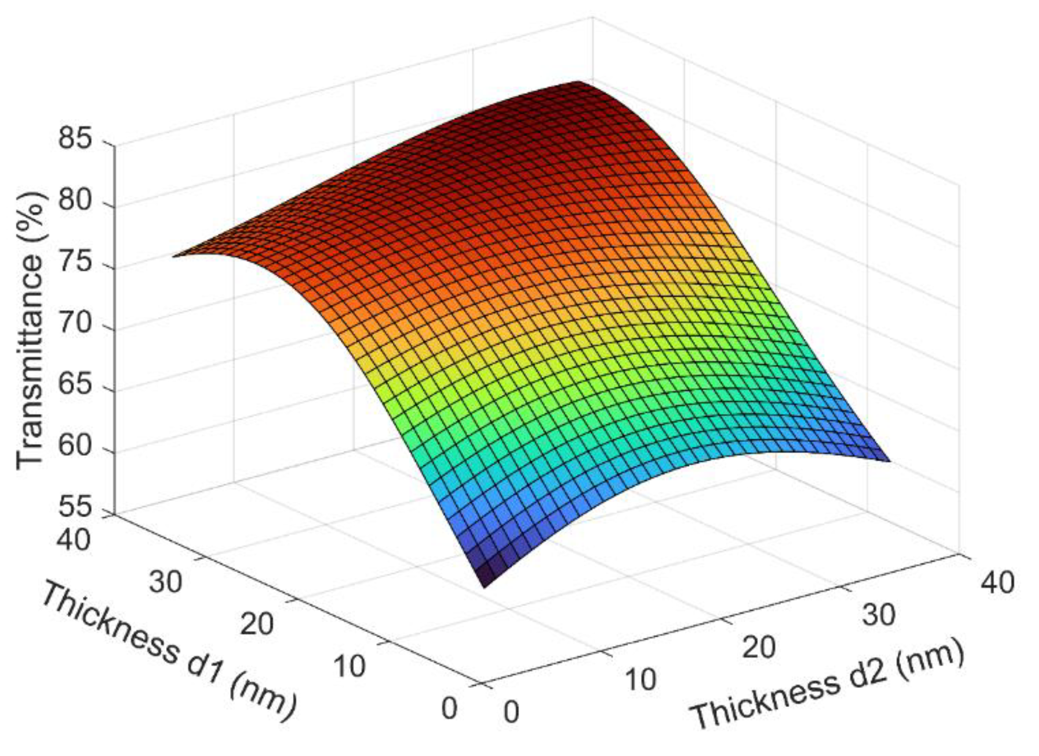
Figure 1. Calculated average transmittance of the polymer/NAN structures as a function of the thickness of the two NiO layers. The wavelength was between 380 nm to 780 nm. The thickness of Ag was fixed at 11 nm.
Micromachines 13 01511 g001
Figure 2. Steps of fabricating ultra-smooth NAN film by template stripping. (a) Si substrate was cleaned as the template. (b) NAN film was deposited onto the Si template by electron beam evaporation. (c) Photopolymer (NOA63) was spin-coated as the backing film. (d) The NAN film adhered to the cured photopolymer film was stripped.
Micromachines 13 01511 g002
Figure 3. AFM images of (a) PET/ITO and (b) Photopolymer/NAN.
Micromachines 13 01511 g003
Figure 4. Performance of OLEDs with NAN and ITO anodes. (a) Current density–voltage characteristics of hole-only devices. (b) Current density–voltage characteristics, (c) luminance–current density characteristics, and (d) efficiency–current density characteristics.
Micromachines 13 01511 g004
Figure 5. Mechanical stability of the flexible OLEDs. (a) Luminance and efficiency at 8 V as a function of the number of bending cycles. (b) Comparison of EL spectra before and after repeated bending.
Micromachines 13 01511 g005
Publisher’s Note: MDPI stays neutral with regard to jurisdictional claims in published maps and institutional affiliations.