
Solitary and Collective Motion Behaviors of TiO2 Microrobots under the Coupling of Multiple Light Fields


Abstract
:1. Introduction
2. Working Principle
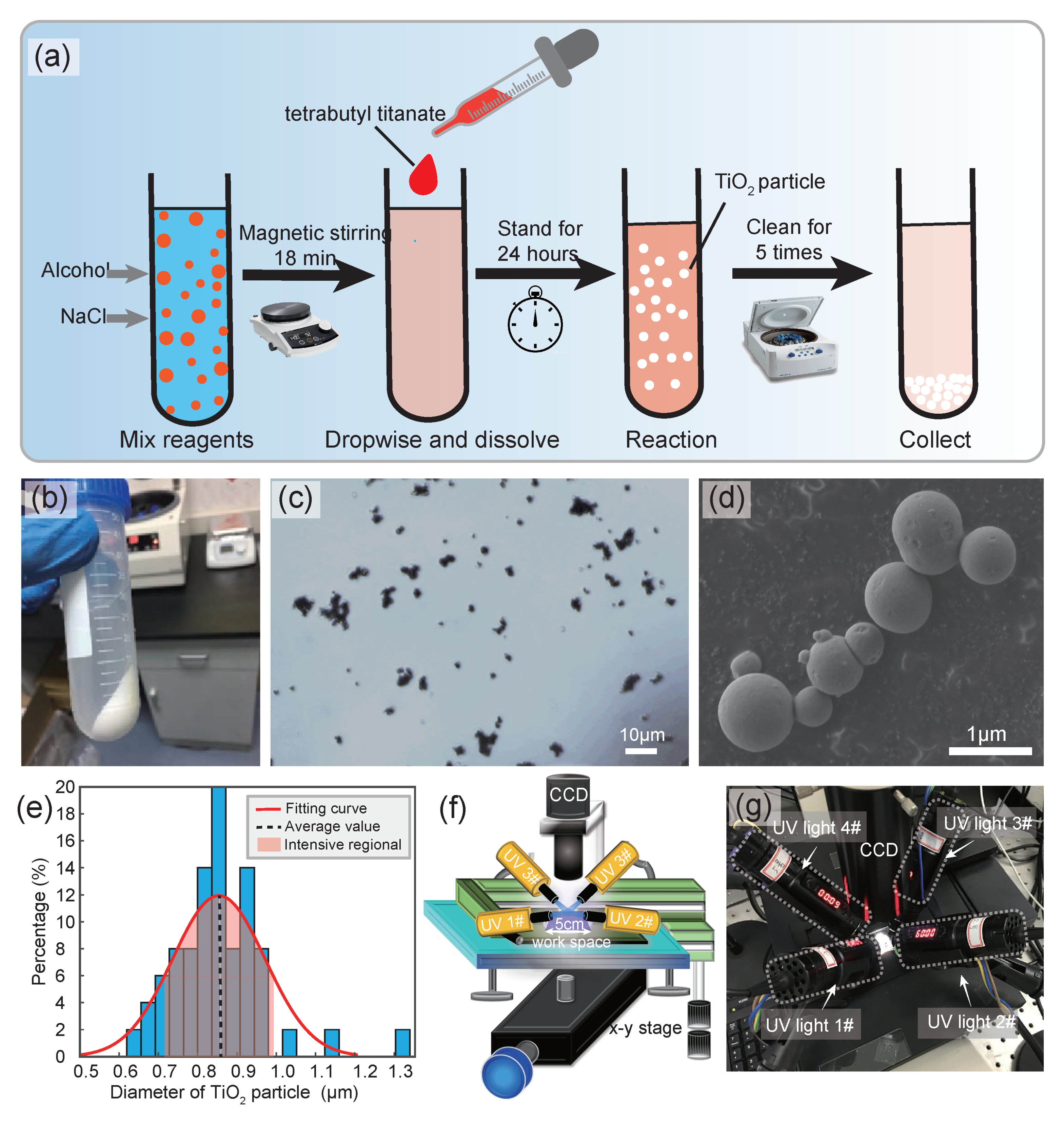
2.1. Preparation of the Microrobot
2.2. Design of the Optical Control Platform
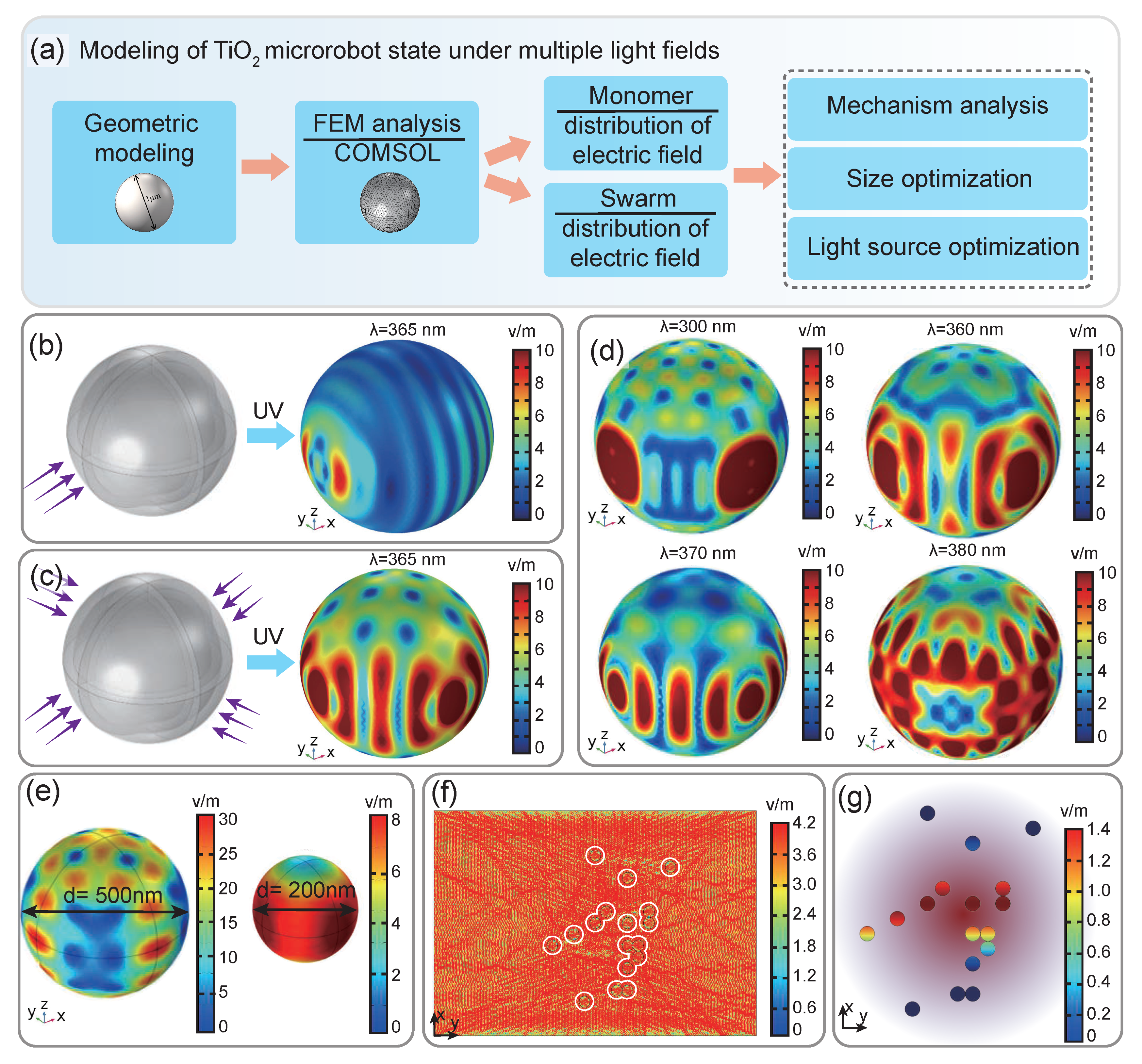
2.3. Numerical Analysis of Microrobots’ Motion Behavior
3. Results and Discussion
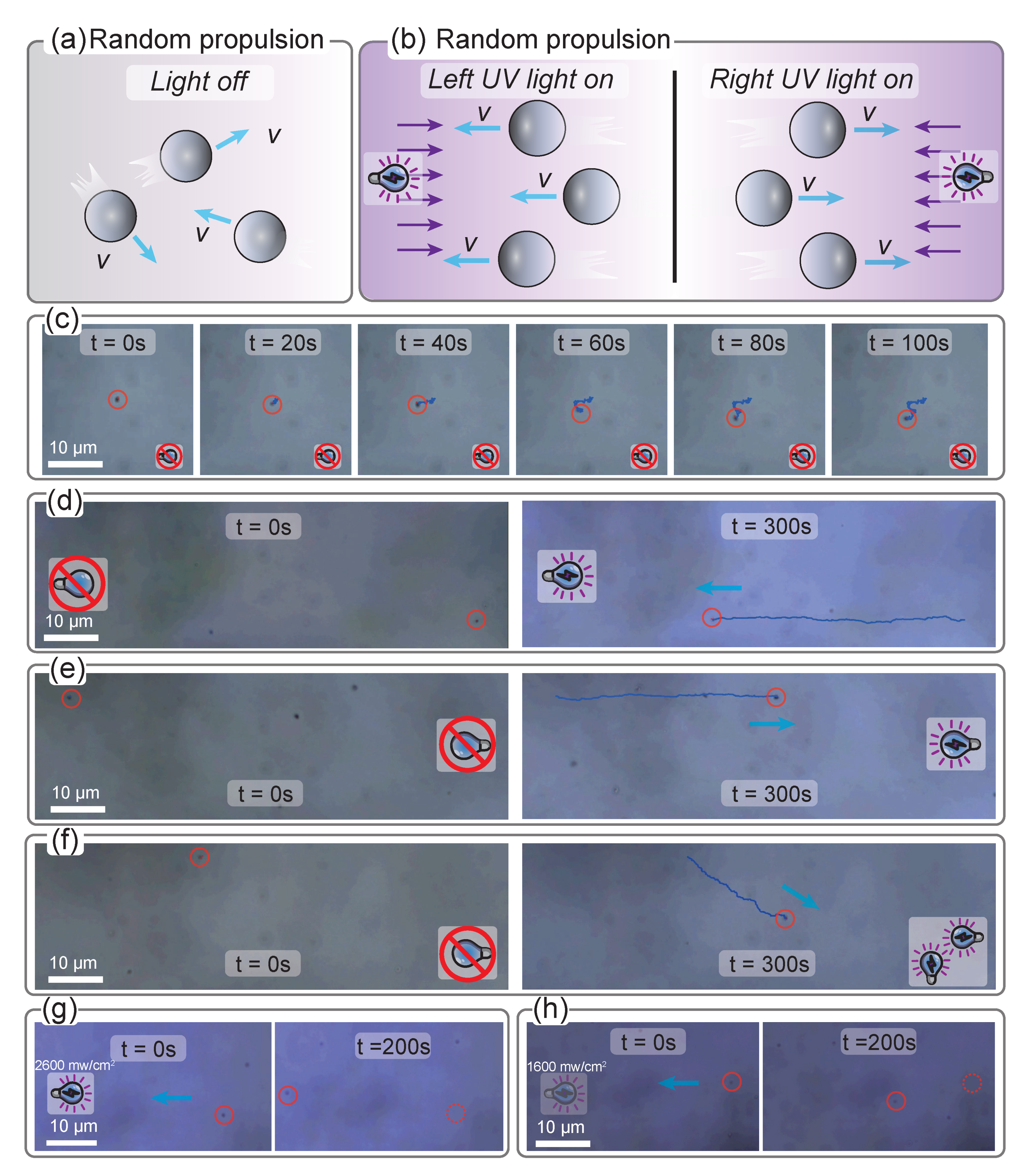
3.1. Solitary Behaviors of the Microrobot under Multiple Light Fields
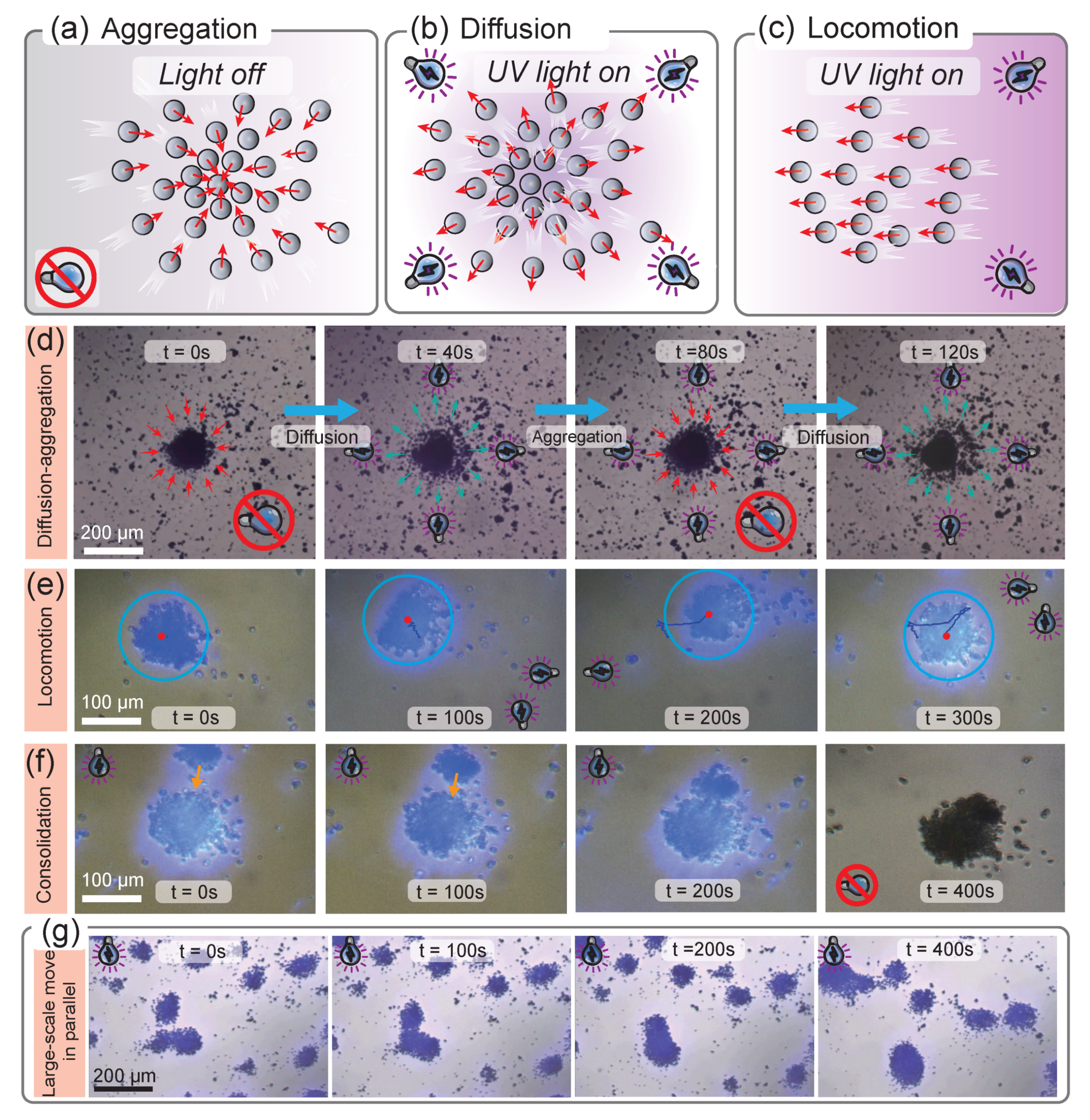
3.2. Collective Behaviors of the Microrobot under Multiple Light Fields
4. Conclusions
Supplementary Materials
Author Contributions
Funding
Institutional Review Board Statement
Informed Consent Statement
Data Availability Statement
Acknowledgments
Conflicts of Interest
References
- Kong, L.; Mayorga, C.C.; Guan, J.; Martin, P. Photocatalytic micromotors activated by UV to visible light for environmental remediation, micropumps, reversible assembly, Transportation, and Biomimicry. Small 2020, 16, e1903179. [Google Scholar] [CrossRef] [PubMed]
- Wang, J.; Xiong, Z.; Tang, J. The encoding of light-driven micro/nanorobots: From single to swarming systems. Adv. Intel. Sys. 2021, 3, 2000170. [Google Scholar] [CrossRef]
- Wang, Q.; Zhang, L. External power-driven microrobotic swarm: From fundamental understanding to imaging-guided delivery. ACS Nano 2021, 15, 149–174. [Google Scholar] [CrossRef] [PubMed]
- De Ávila, B.E.; Angsantikul, P.; Li, J.; Lopez-Ramirez, M.; Ramirez-Herrera, D.; Thamphiwatana, S.; Chen, C.; Delezuk, J.; Samakapiruk, R.; Ramez, V.; et al. Micromotor-enabled active drug delivery for in vivo treatment of stomach infection. Nat. Commun. 2017, 8, 272. [Google Scholar]
- Esteban-Fernández De Ávila, B.; Angsantikul, P.; Li, J.; Gao, W.; Zhang, L.; Wang, J. Micromotors go in vivo: From test tubes to live animals. Adv. Funct. Mater. 2018, 28, 1705640. [Google Scholar]
- Esteban-Fernández De Ávila, B.; Angsantikul, P.; Ramirez-Herrera, D.E.; Soto, F.; Teymourian, H.; Dehaini, D.; Chen, Y.; Zhang, L.; Wang, J. Hybrid biomembrane-functionalized nanorobots for concurrent removal of pathogenic bacteria and toxins. Sci. Robot. 2018, 3, eaat0485. [Google Scholar]
- Gao, W.; De Ávila, B.E.F.; Zhang, L.; Wang, J. Targeting and isolation of cancer cells using micro/nanomotors. Adv. Drug. Deliv. Rev. 2018, 125, 94–101. [Google Scholar] [CrossRef] [PubMed]
- Hansen-Bruhn, M.; De Ávila, B.E.F.; Gastelum, M.; Zhao, J.; Ramirez-Herrera, D.E.; Angsantikul, P.; Gothelf, K.v.; Zhang, L.; Wang, J. Active intracellular delivery of a Cas9/sgRNA complex using ultrasound propelled nanomotors. Angew. Chem. Int. Ed. Engl. 2018, 57, 2657–2661. [Google Scholar] [CrossRef]
- Chen, C.; Soto, F.; Karshalev, E.; Li, j.; Wang, J. Hybrid nanovehicles: One machine, two engines. Adv. Funct. Mater. 2019, 29, 1806290. [Google Scholar] [CrossRef]
- Li, J.; Singh, V.V.; Sattayasamitsathit, S.; Orozco, J.; Kaufmann, K.; Dong, R.; Gao, W.; Jurado-Sanchez, B.; Fedorak, Y.; Wang, J. Water-driven micromotors for rapid photocatalytic degradation of biological and chemical warfare agents. ACS Nano 2014, 8, 11118–11125. [Google Scholar] [CrossRef] [Green Version]
- Hamilton, J.K.; Petrov, P.G.; Winlove, C.P.; Gilbert, A.D.; Bryan, M.T.; Ogrin, F.Y. Magnetically controlled ferromagnetic swimmers. Sci. Rep. 2017, 7, 1–7. [Google Scholar] [CrossRef] [PubMed] [Green Version]
- Zhong, D.; Li, W.; Qi, Y.; He, J.; Zhou, M. Photosynthetic biohybrid nanoswimmers system to alleviate tumor hypoxia for FL/PA/MR imaging-guided enhanced radio-photodynamic synergetic therapy. Adv. Funct. Mater. 2020, 30, 1910395. [Google Scholar] [CrossRef]
- Zhu, Q.; Xu, T.; Song, Y.; Luo, Y.; Xu, L.; Zhang, X. Integrating modification and detection in acoustic microchip for in-situ analysis. Biosens. Bioelectron. 2020, 158, 112185. [Google Scholar] [CrossRef] [PubMed]
- Mou, F.; Li, Y.; Chen, C.; Li, W.; Yin, Y.; Ma, H.; Guan, J. Single-component TiO2 tubular microengines with motion controlled by light-induced bubbles. Small 2015, 11, 2564–2570. [Google Scholar] [CrossRef]
- Xu, P.; Yu, Y.; Li, T.; Chen, H.; Wang, Q.; Wang, M.; Wan, M.; Mao, C. Near-infrared-driven fluorescent nanomotors for detection of circulating tumor cells in whole blood. Anal. Chim. Acta 2020, 1129, 60–68. [Google Scholar] [CrossRef] [PubMed]
- Jiao, X.; Wang, Z.; Xiu, J.; Dai, W.; Zhao, L.; Xu, T.; Du, X.; Wen, Y.; Zhang, X. NIR powered Janus nanocarrier for deep tumor penetration. Appl. Mater. Today 2020, 18, 100504. [Google Scholar] [CrossRef]
- Wang, X.; Baraban, L.; Nguyen, A.; Ge, J.; Misko, V.R.; Tempere, J.; Nori, F.; Formanek, P.; Huang, T.; Cuniberti, G.; et al. High-motility visible light-driven Ag/AgCl Janus micromotors. Small 2018, 14, 1803613. [Google Scholar] [CrossRef]
- Xie, H.; Sun, M.; Fan, X.; Lin, Z.; Chen, W.; Wang, L.; Dong, L.; He, Q. Reconfigurable magnetic microrobot swarm: Multimode transformation, locomotion, and manipulation. Sci. Robot. 2019, 4, aav8006. [Google Scholar] [CrossRef] [PubMed]
- Dong, X.; Sitti, M. Controlling two-dimensional collective formation and cooperative behavior of magnetic microrobot swarms. Int. J. Robot. Res. 2020, 39, 617–638. [Google Scholar] [CrossRef]
- Sun, M.; Chen, W.; Fan, X.; Tian, C.; Sun, L.; Xie, H. Cooperative recyclable magnetic microsubmarines for oil and microplastics removal from water. Appl. Mater. Today 2020, 20, 100682. [Google Scholar] [CrossRef]
- Jiang, H.; He, X.; Ma, Y.; Fu, B.; Xu, X.; Subramanian, B.; Hu, C. Isotropic hedgehog-shaped- TiO2/functional-multiwall-carbon-nanotube micromotors with phototactic motility in fuel-free environments. ACS Appl. Mater. Inter. 2021, 13, 5406–5417. [Google Scholar] [CrossRef]
- Sun, Y.; Liu, Y.; Zhang, D.; Zhang, H.; Jiang, J.; Duan, R.; Xiao, J.; Xing, J.; Zhang, D.; Dong, B. Calligraphy/painting based on a bioinspired light-driven micromotor with concentration-dependent motion direction reversal and dynamic swarming behavior. ACS Appl. Mater. Inter. 2019, 11, 40533–40542. [Google Scholar] [CrossRef] [PubMed]
- Zhou, D.; Gao, Y.; Liu, H.; Zhang, G.; Li, L. Light-induced patterned self-assembly behavior of isotropic semiconductor nanomotors. Chem.-Asian J. 2019, 14, 2445–2449. [Google Scholar] [CrossRef]
- Maric, T.; Nasir, M.; Webster, R.; Pumera, M. Tailoring metal/TiO2 interface to influence motion of light-activated Janus micromotors. Adv. Funct. Mater. 2020, 30, 1908614. [Google Scholar] [CrossRef]
- Mou, F.; Zhang, J.; Wu, Z.; Du, S.; Zhang, Z.; Xu, L.; Guan, J. Phototactic flocking of photochemical micromotors. iScience 2019, 19, 415–424. [Google Scholar] [CrossRef] [PubMed] [Green Version]
- Wang, X.; Baraban, L.; Misko, V.; Nori, F.; Huang, T.; Cuniberti, G.; Fassbender, J.; Makarov, D. Visible light actuated eficient exclusion between plasmonic Ag/AgCl micromotors and passive beads. Small 2018, 14, 1802537. [Google Scholar] [CrossRef] [PubMed]
- Tong, J.; Wang, D.; Wang, D.; Xu, F.; Duan, R.; Zhang, D.; Fan, J. Visible-light-driven-water-fueled ecofriendly micromotors based on iron phthalocyanine for highly efficient organic pollutant degradation. Langmuir 2020, 36, 6930–6937. [Google Scholar] [CrossRef]
- Orozco, C.; Liu, D.; Li, Y.; Alemany, L.B.; Pal, R.; Krishnan, S.; Tour, J.M. Visible-light-activated molecular nanomachines kill pancreatic cancer cells. ACS Appl. Mater. Inter. 2020, 12, 410–417. [Google Scholar] [CrossRef]
- Xu, T.; Xu, L.; Zhang, X. Ultrasound propulsion of micro-nanomotors. Appl. Mater. Today 2017, 9, 493–503. [Google Scholar] [CrossRef]
- Chen, K.; Gu, C.; Yang, Z.; Nakajima, M.; Chen, T.; Fukuda, T. “Z”-shaped rotational Au/Pt micro-nanorobot. Micromachines 2017, 8, 183. [Google Scholar] [CrossRef] [Green Version]
- Chen, C.; Mou, F.; Xu, L.; Wang, S.; Guan, J.; Feng, Z.; Wang, Q.; Kong, L.; Li, W.; Wang, J.; et al. Light-steered isotropic semiconductor micromotors. Adv. Mater. 2017, 29, 1603374. [Google Scholar] [CrossRef] [PubMed]
- Guo, X.; Wang, Y.; Mou, F.; Xie, Q.; Su, S.; Chen, C.; Guan, J. Phototactic micromotor assemblies in dynamic line formations for wide-range micromanipulations. J. Mater. Chem. C 2022, 10, 5079–5087. [Google Scholar] [CrossRef]
Disclaimer/Publisher’s Note: The statements, opinions and data contained in all publications are solely those of the individual author(s) and contributor(s) and not of MDPI and/or the editor(s). MDPI and/or the editor(s) disclaim responsibility for any injury to people or property resulting from any ideas, methods, instructions or products referred to in the content. |
© 2022 by the authors. Licensee MDPI, Basel, Switzerland. This article is an open access article distributed under the terms and conditions of the Creative Commons Attribution (CC BY) license (https://creativecommons.org/licenses/by/4.0/).
Share and Cite
Fan, X.; Hu, Q.; Zhang, X.; Sun, L.; Yang, Z. Solitary and Collective Motion Behaviors of TiO2 Microrobots under the Coupling of Multiple Light Fields. Micromachines 2023, 14, 89. https://doi.org/10.3390/mi14010089
Fan X, Hu Q, Zhang X, Sun L, Yang Z. Solitary and Collective Motion Behaviors of TiO2 Microrobots under the Coupling of Multiple Light Fields. Micromachines. 2023; 14(1):89. https://doi.org/10.3390/mi14010089
Chicago/Turabian StyleFan, Xinjian, Qihang Hu, Xin Zhang, Lining Sun, and Zhan Yang. 2023. "Solitary and Collective Motion Behaviors of TiO2 Microrobots under the Coupling of Multiple Light Fields" Micromachines 14, no. 1: 89. https://doi.org/10.3390/mi14010089