
Tunable Helmholtz Resonators Using Multiple Necks


Abstract
:1. Introduction
2. Methods
2.1. Theoretical Formulation (Single Neck, Multi-Neck)
2.1.1. Single Neck
2.1.2. Multi-Neck
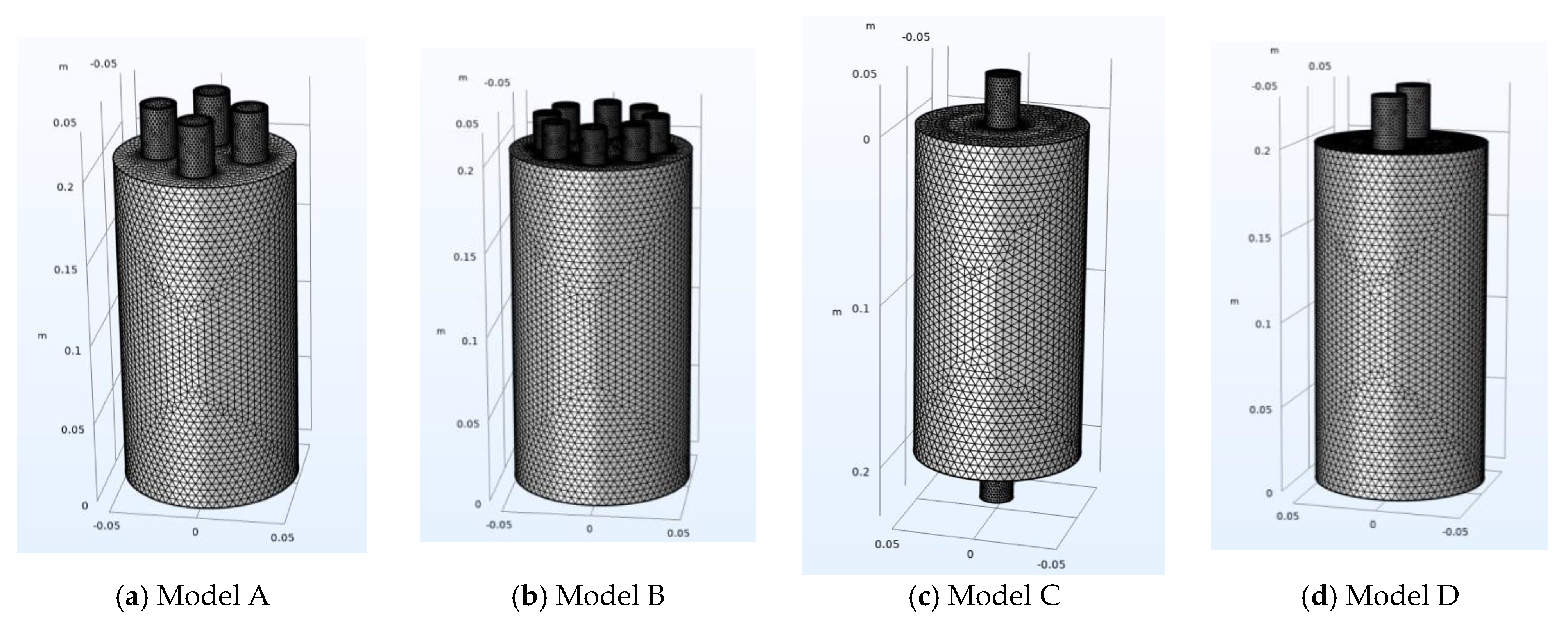
2.2. FEM Formulation and Setup
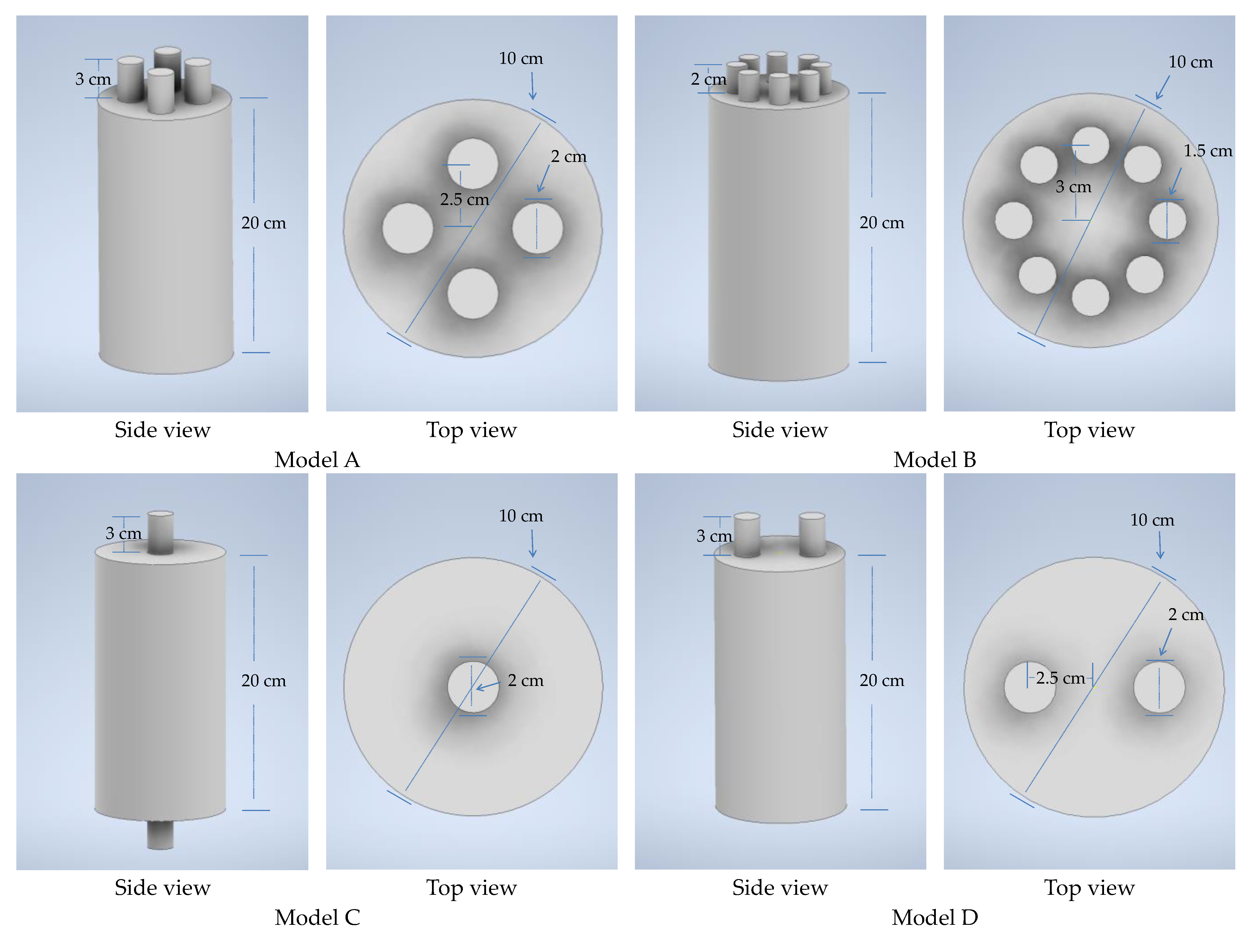
2.3. 3D Models
3. Results
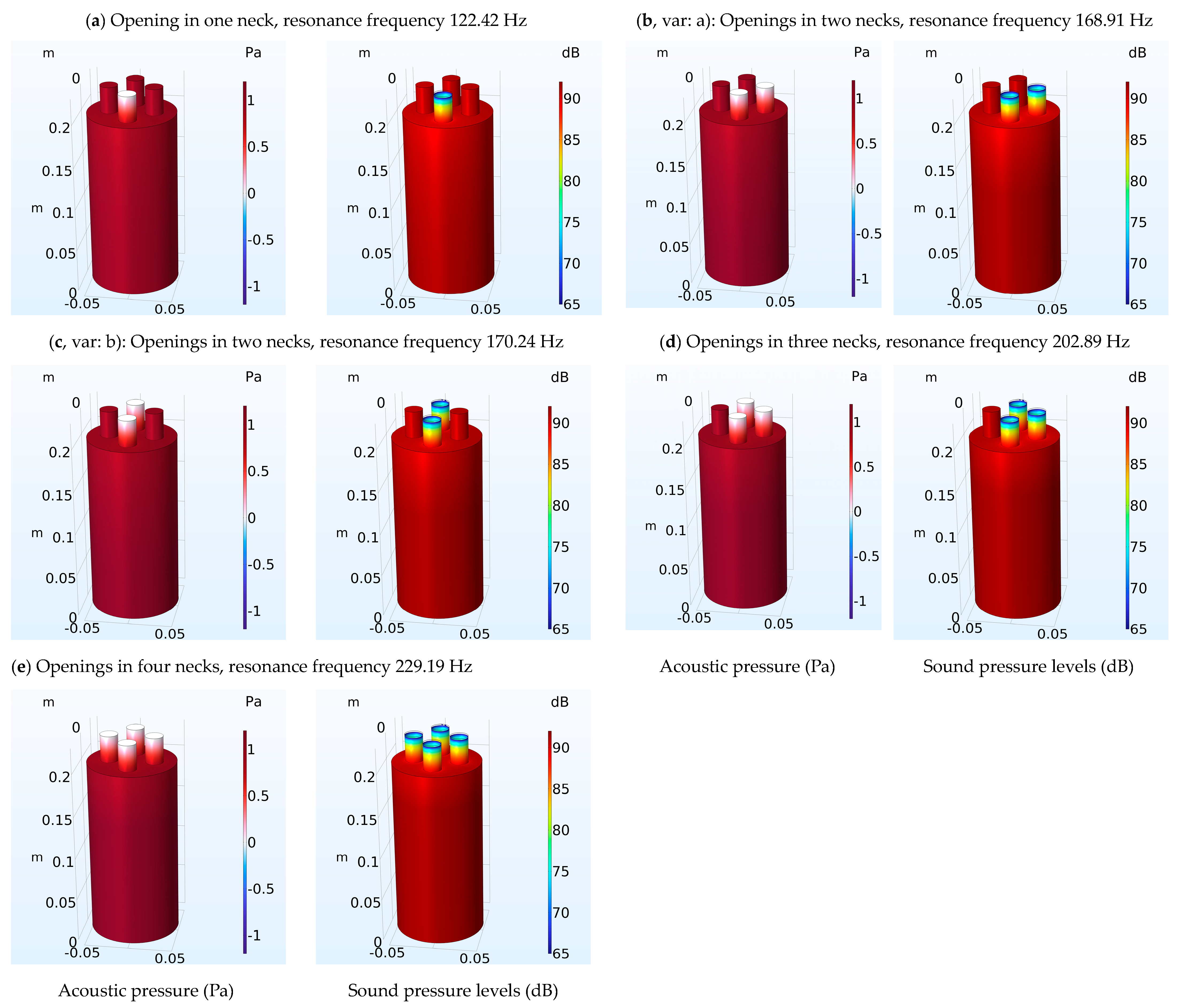
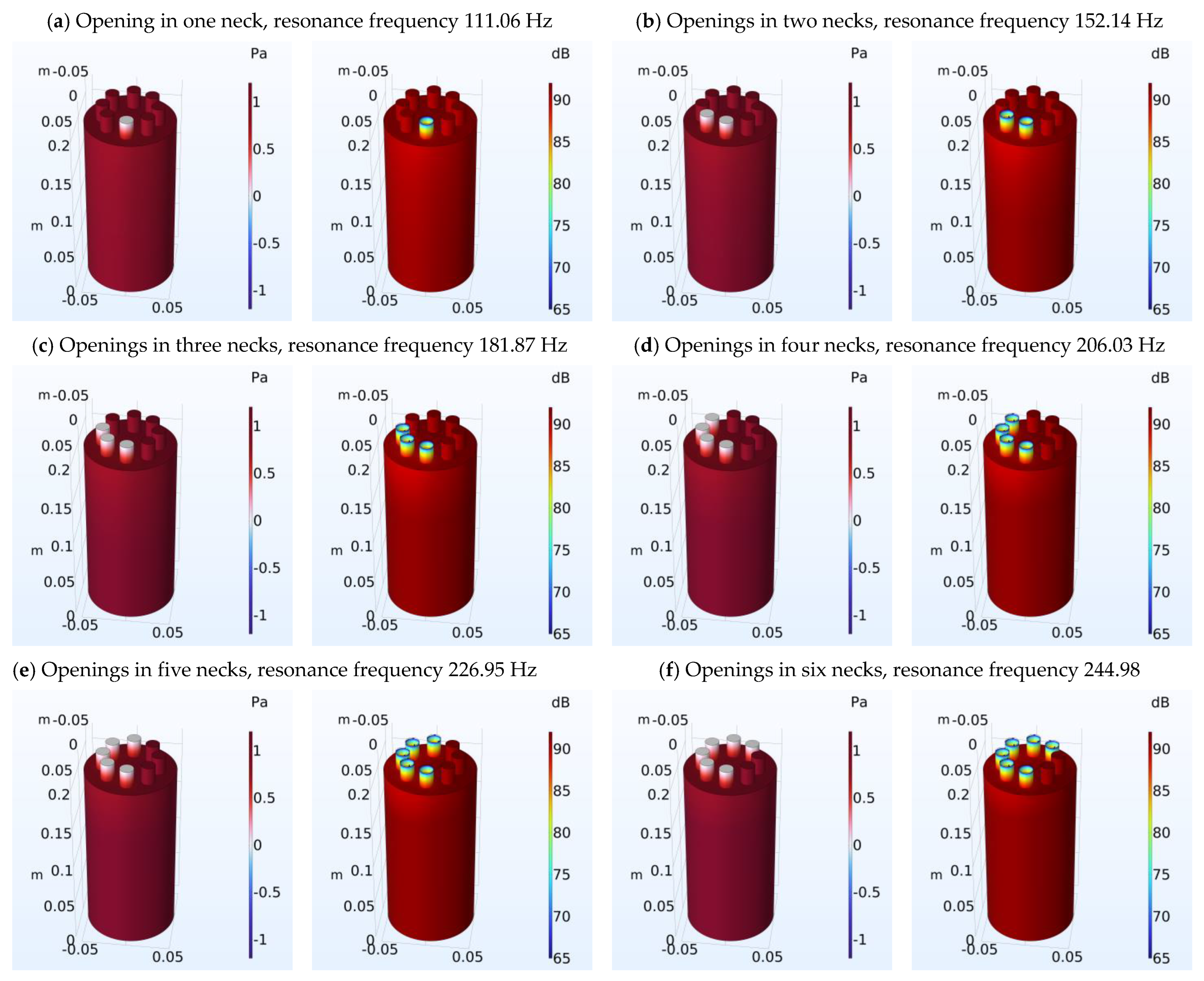
Multi-Neck Helmholtz Resonators with Same Number of Necks
4. Discussion
4.1. Analytical and FEM Approach Differences
4.2. Possible Applications
5. Conclusions
Author Contributions
Funding
Data Availability Statement
Conflicts of Interest
References
- ISO 3382-1: 2009; Measurement of Room Acoustic Parameters—Part 1: Performance spaces. ISO: Geneva, Switzerland, 2009.
- Long, M. Architectural Acoustics; Elsevier: Amsterdam, The Netherlands, 2005; Volume 208. [Google Scholar]
- Cao, L.; Fu, Q.; Si, Y.; Ding, B.; Yu, J. Porous materials for sound absorption. Compos. Commun. 2018, 10, 25–35. [Google Scholar] [CrossRef]
- Kalauni, K.; Pawar, S. A review on the taxonomy, factors associated with sound absorption and theoretical modeling of porous sound absorbing materials. J. Porous Mater. 2019, 26, 1795–1819. [Google Scholar] [CrossRef]
- Carbajo, J.; Ramis, J.; Godinho, L.; Amado-Mendes, P. Perforated panel absorbers with micro-perforated partitions. Appl. Acoust. 2019, 149, 108–113. [Google Scholar] [CrossRef]
- Rossing, T.D.; Rossing, T.D. Springer Handbook of Acoustics; Springer: Berlin/Heidelberg, Germany, 2014. [Google Scholar]
- Komkin, A.; Mironov, M.; Bykov, A. Sound absorption by a Helmholtz resonator. Acoust. Phys. 2017, 63, 385–392. [Google Scholar] [CrossRef]
- Padhye, R.; Nayak, R. Acoustic Textiles; Springer: Berlin/Heidelberg, Germany, 2016. [Google Scholar]
- Kanev, N. Resonant Vessels in Russian Churches and Their Study in a Concert Hall. Acoustics 2020, 2, 399–415. [Google Scholar] [CrossRef]
- Mijic, M.; Sumarac-Pavlovic, D. Analysis of contribution of acoustic resonators found in Serbian Orthodox churches. Build. Acoust. 2004, 11, 197–212. [Google Scholar] [CrossRef]
- Desarnaulds, V.; Loerincik, Y.; Carvalho, A.P. Efficiency of 13th-century acoustic ceramic pots in two Swiss churches. In Proceedings of the 2001 National Conference on Noise Control Engineering, Hague, The Netherlands, 27–30 August 2001. [Google Scholar]
- Pöhlmann, E. Vitruvius De Architectura V: Resounding Vessels in the Greek and Roman Theatre and Their Possible Afterlife in Eastern and Western Churches. Greek Rom. Music. Stud. 2021, 9, 157–174. [Google Scholar] [CrossRef]
- Gilford, C. Helmholtz resonators in the acoustic treatment of broadcasting studios. Br. J. Appl. Phys. 1952, 3, 86. [Google Scholar] [CrossRef]
- Namvar Arefi, H.; Ghiasi, S.M.A.; Ghaffari, S.M.; Ramezanghorbani, F.; Sharifpour, S.; Irajizad, P.; Ghoreishi Langroudi, S.D.; Amjadi, A. Conference room reverberation time correction using helmholtz resonators lined with absorbers. Shock Vib. 2014, 2014, 472524. [Google Scholar] [CrossRef]
- Klaus, J.; Bork, I.; Graf, M.; Ostermeyer, G.-P. On the adjustment of Helmholtz resonators. Appl. Acoust. 2014, 77, 37–41. [Google Scholar] [CrossRef]
- Asakura, T. Numerical investigation of the sound-insulation effect of a suspended ceiling structure with arrayed Helmholtz resonators by the finite-difference time-domain method. Appl. Acoust. 2021, 172, 107601. [Google Scholar] [CrossRef]
- Kanev, N. Maximum sound absorption by a Helmholtz resonator in a room at low frequencies. Acoust. Phys. 2018, 64, 774–777. [Google Scholar] [CrossRef]
- Herrero-Durá, I.; Cebrecos, A.; Picó, R.; Romero-García, V.; García-Raffi, L.M.; Sánchez-Morcillo, V.J. Sound absorption and diffusion by 2D arrays of Helmholtz resonators. Appl. Sci. 2020, 10, 1690. [Google Scholar] [CrossRef]
- Huang, S.; Fang, X.; Wang, X.; Assouar, B.; Cheng, Q.; Li, Y. Acoustic perfect absorbers via Helmholtz resonators with embedded apertures. J. Acoust. Soc. Am. 2019, 145, 254–262. [Google Scholar] [CrossRef]
- Mahesh, K.; Kumar Ranjith, S.; Mini, R. Inverse design of a Helmholtz resonator based low-frequency acoustic absorber using deep neural network. J. Appl. Phys. 2021, 129, 174901. [Google Scholar] [CrossRef]
- Vergara, E.; Almeida, G.; Barbosa, L.; Lenzi, A.; Carvalho de Sousa, A. Broadband and low-frequency sound absorption of modified Helmholtz resonator combined with porous layer addition. J. Appl. Phys. 2022, 132, 135114. [Google Scholar] [CrossRef]
- Papadakis, N.M.; Stavroulakis, G.E. Review of Acoustic Sources Alternatives to a Dodecahedron Speaker. Appl. Sci. 2019, 9, 3705. [Google Scholar] [CrossRef]
- Papadakis, N.M.; Stavroulakis, G.E. Handclap for Acoustic Measurements: Optimal Application and Limitations. Acoustics 2020, 2, 224–245. [Google Scholar] [CrossRef]
- Papadakis, N.M.; Antoniadou, S.; Stavroulakis, G.E. Effects of Varying Levels of Background Noise on Room Acoustic Parameters, Measured with ESS and MLS Methods. Acoustics 2023, 5, 563–574. [Google Scholar] [CrossRef]
- Nia, H.T.; Jain, A.D.; Liu, Y.; Alam, M.-R.; Barnas, R.; Makris, N.C. The evolution of air resonance power efficiency in the violin and its ancestors. Proc. R. Soc. A Math. Phys. Eng. Sci. 2015, 471, 20140905. [Google Scholar] [CrossRef]
- Papadakis, N.M.; Stavroulakis, G.E. FEM Investigation of the Air Resonance in a Cretan Lyra. VIbration 2023, 2023091035. [Google Scholar]
- Garcia-Alcaide, V.; Palleja-Cabre, S.; Castilla, R.; Gamez-Montero, P.J.; Romeu, J.; Pamies, T.; Amate, J.; Milán, N. Numerical study of the aerodynamics of sound sources in a bass-reflex port. Eng. Appl. Comput. Fluid Mech. 2017, 11, 210–224. [Google Scholar] [CrossRef]
- Yuan, M.; Cao, Z.; Luo, J.; Chou, X. Recent developments of acoustic energy harvesting: A review. Micromachines 2019, 10, 48. [Google Scholar] [CrossRef]
- Kone, C.T.; Ghinet, S.; Panneton, R.; Dupont, T.; Grewal, A. Multi-tonal low frequency noise control for aircraft cabin using Helmholtz resonator with complex cavity designs for aircraft cabin noise improvement. In Proceedings of the INTERNOISE-2021, Washington, DC, USA, 1–5 August 2021. [Google Scholar]
- Wang, J.; Rubini, P.; Qin, Q.; Houston, B. A model to predict acoustic resonant frequencies of distributed Helmholtz resonators on gas turbine engines. Appl. Sci. 2019, 9, 1419. [Google Scholar] [CrossRef]
- Fang, N.; Xi, D.; Xu, J.; Ambati, M.; Srituravanich, W.; Sun, C.; Zhang, X. Ultrasonic metamaterials with negative modulus. Nat. Mater. 2006, 5, 452–456. [Google Scholar] [CrossRef]
- Cai, C.; Mak, C.-M.; Shi, X. An extended neck versus a spiral neck of the Helmholtz resonator. Appl. Acoust. 2017, 115, 74–80. [Google Scholar] [CrossRef]
- Shi, X.; Mak, C.M. Helmholtz resonator with a spiral neck. Appl. Acoust. 2015, 99, 68–71. [Google Scholar] [CrossRef]
- Tang, S.K. On Helmholtz resonators with tapered necks. J. Sound Vib. 2005, 279, 1085–1096. [Google Scholar] [CrossRef]
- Ramos, D.; Godinho, L.; Amado-Mendes, P.; Mareze, P. Experimental and numerical modelling of Helmholtz Resonator with angled neck aperture. In Proceedings of the INTER-NOISE and NOISE-CON Congress and Conference Proceedings, Seoul, Republic of Korea, 23–26 August 2020; pp. 37–47. [Google Scholar]
- Duan, M.; Yu, C.; He, W.; Xin, F.; Lu, T.J. Perfect sound absorption of Helmholtz resonators with embedded channels in petal shape. J. Appl. Phys. 2021, 130. [Google Scholar] [CrossRef]
- Chanaud, R. Effects of geometry on the resonance frequency of Helmholtz resonators. J. Sound Vib. 1994, 178, 337–348. [Google Scholar] [CrossRef]
- Chanaud, R. Effects of geometry on the resonance frequency of Helmholtz resonators, part II. J. Sound Vib. 1997, 204, 829–834. [Google Scholar] [CrossRef]
- Langfeldt, F.; Hoppen, H.; Gleine, W. Resonance frequencies and sound absorption of Helmholtz resonators with multiple necks. Appl. Acoust. 2019, 145, 314–319. [Google Scholar] [CrossRef]
- Selamet, A.; Kim, H.; Huff, N.T. Leakage effect in Helmholtz resonators. J. Acoust. Soc. Am. 2009, 126, 1142–1150. [Google Scholar] [CrossRef] [PubMed]
- Lee, I.; Jeon, K.; Park, J. The effect of leakage on the acoustic performance of reactive silencers. Appl. Acoust. 2013, 74, 479–484. [Google Scholar] [CrossRef]
- Papadakis, N.M.; Stavroulakis, G.E. FEM Investigation of a Multi-Neck Helmholtz Resonator. Appl. Sci. 2023. [Google Scholar] [CrossRef]
- Li, M.; Wu, J.H.; Yuan, X.Y. Metasurface zero-impedance matching mechanism for aerodynamic noise reduction. J. Sound Vib. 2022, 536, 117147. [Google Scholar] [CrossRef]
- Zolfagharian, A.; Noshadi, A.; Khosravani, M.R.; Zain, M.Z.M. Unwanted noise and vibration control using finite element analysis and artificial intelligence. Appl. Math. Model. 2014, 38, 2435–2453. [Google Scholar] [CrossRef]
- Sakuma, T.; Sakamoto, S.; Otsuru, T. Computational Simulation in Architectural and Environmental Acoustics; Springer: Berlin/Heidelberg, Germany, 2014. [Google Scholar]
- Prinn, A.G. A Review of Finite Element Methods for Room Acoustics. Acoustics 2023, 5, 367–395. [Google Scholar] [CrossRef]
- Yoshida, T.; Okuzono, T.; Sakagami, K. Binaural Auralization of Room Acoustics with a Highly Scalable Wave-Based Acoustics Simulation. Appl. Sci. 2023, 13, 2832. [Google Scholar] [CrossRef]
- Hoshi, K.; Hanyu, T.; Okuzono, T.; Sakagami, K.; Yairi, M.; Harada, S.; Takahashi, S.; Ueda, Y. Implementation experiment of a honeycomb-backed MPP sound absorber in a meeting room. Appl. Acoust. 2020, 157, 107000. [Google Scholar] [CrossRef]
- Papadakis, N.M.; Stavroulakis, G.E. Finite Element Method for the Estimation of Insertion Loss of Noise Barriers: Comparison with Various Formulae (2D). Urban Sci. 2020, 4, 77. [Google Scholar] [CrossRef]
- Papadakis, N.M.; Stavroulakis, G.E. Time domain finite element method for the calculation of impulse response of enclosed spaces. Room acoustics application. In Proceedings of the Mechanics of Hearing: Protein to Perception—Proceedings of the 12th International Workshop on the Mechanics of Hearing, Cape Sounio, Greece, 23–29 June 2014; Volume 1703, p. 100002. [Google Scholar] [CrossRef]
- Yoshida, T.; Okuzono, T.; Sakagami, K. A parallel dissipation-free and dispersion-optimized explicit time-domain fem for large-scale room acoustics simulation. Buildings 2022, 12, 105. [Google Scholar] [CrossRef]
- Blackstock, D.T. Fundamentals of physical acoustics. J. Acoust. Soc. Am. 2001, 109, 1274–1276. [Google Scholar]
- Ingard, U. Notes on Acoustics; Laxmi Publications, Ltd.: Delhi, India, 2010. [Google Scholar]
- Kuttruff, H. Room Acoustics; CRC Press: Boca Raton, FL, USA, 2016. [Google Scholar] [CrossRef]
- Crocker, M.J.; Arenas, J.P. Engineering Acoustics: Noise and Vibration Control; John Wiley & Sons: Hoboken, NJ, USA, 2021. [Google Scholar]
- Beranek, L.L.; Mellow, T. Acoustics: Sound Fields and Transducers; Academic Press: Cambridge, MA, USA, 2012. [Google Scholar]
- Marburg, S.; Nolte, B. Computational Acoustics of Noise Propagation in Fluids: Finite and Boundary Element Methods; Springer: Berlin/Heidelberg, Germany, 2008; Volume 578. [Google Scholar]
- Ihlenburg, F. Finite Element Analysis of Acoustic Scattering; Springer Science & Business Media: Berlin/Heidelberg, Germany, 2006; Volume 132. [Google Scholar]
- Jena, D.; Dandsena, J.; Jayakumari, V. Demonstration of effective acoustic properties of different configurations of Helmholtz resonators. Appl. Acoust. 2019, 155, 371–382. [Google Scholar] [CrossRef]
- Cremer, L. The Physics of Violin; MIT Press: Cambridge, MA, USA, 1984. [Google Scholar]


| Number of Necks | Resonant Frequency Analytical (Hz) | Resonant Frequency FEM (Hz) | Error of Calculation (%) Analytical-FEM |
|---|---|---|---|
| 1 | 124.37 | 122.42 | 1.56 |
| 2 (var. a) | 176.15 | 168.91 | 4.11 |
| 2 (var. b) | 176.15 | 170.24 | 3.35 |
| 3 | 216.06 | 202.89 | 6.10 |
| 4 | 249.85 | 229.19 | 7.91 |
| Number of Necks | Resonant Frequency Analytical (Hz) | Resonant Frequency FEM (Hz) | Error of Calculation (%) Analytical-FEM |
|---|---|---|---|
| 1 | 112.91 | 111.06 | 1.16 |
| 2 | 159.77 | 152.14 | 4.78 |
| 3 | 195.79 | 181.87 | 7.11 |
| 4 | 226.20 | 206.03 | 8.92 |
| 5 | 253.04 | 226.95 | 10.31 |
| 6 | 277.35 | 244.98 | 11.67 |
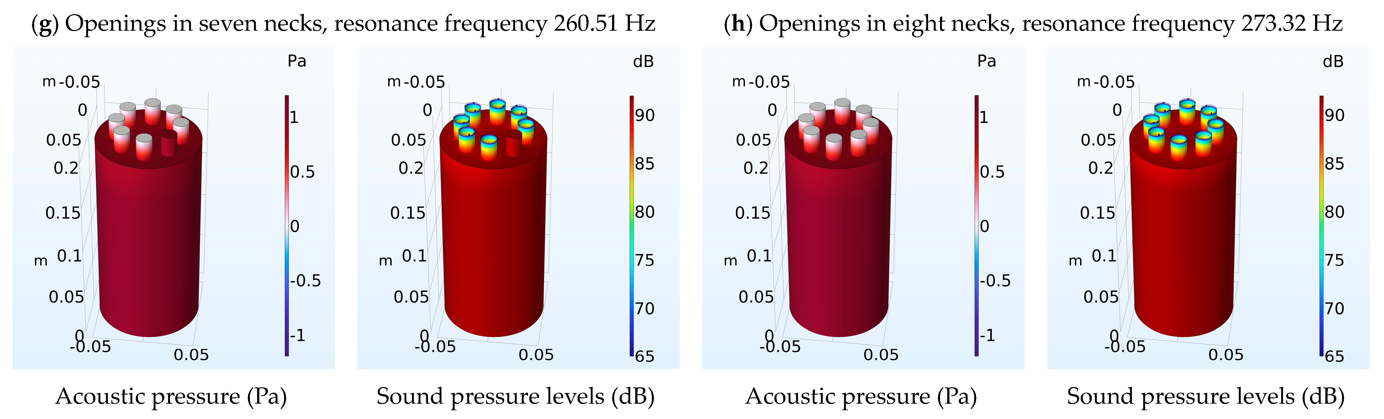
| 7 | 299.73 | 260.51 | 13.09 |
| 8 | 320.61 | 273.32 | 14.78 |
| Number of Necks | Resonant Frequency Analytical (Hz) | Resonant Frequency FEM (Hz) | Error of Calculation (%) Analytical-FEM |
|---|---|---|---|
| 1 | 125.11 | 123.86 | 0.99 |
| 1 | 125.11 | 123.86 | 0.99 |
| 2 | 176.73 | 178.78 | 1.19 |
| Number of Necks | Resonant Frequency Analytical (Hz) | Resonant Frequency FEM (Hz) | Error of Calculation (%) Analytical-FEM |
|---|---|---|---|
| 1 | 125.11 | 123.11 | 0.99 |
| 1 | 125.11 | 123.11 | 0.99 |
| 2 | 176.73 | 171.12 | 3.17 |
Disclaimer/Publisher’s Note: The statements, opinions and data contained in all publications are solely those of the individual author(s) and contributor(s) and not of MDPI and/or the editor(s). MDPI and/or the editor(s) disclaim responsibility for any injury to people or property resulting from any ideas, methods, instructions or products referred to in the content. |
© 2023 by the authors. Licensee MDPI, Basel, Switzerland. This article is an open access article distributed under the terms and conditions of the Creative Commons Attribution (CC BY) license (https://creativecommons.org/licenses/by/4.0/).
Share and Cite
Papadakis, N.M.; Stavroulakis, G.E. Tunable Helmholtz Resonators Using Multiple Necks. Micromachines 2023, 14, 1932. https://doi.org/10.3390/mi14101932
Papadakis NM, Stavroulakis GE. Tunable Helmholtz Resonators Using Multiple Necks. Micromachines. 2023; 14(10):1932. https://doi.org/10.3390/mi14101932
Chicago/Turabian StylePapadakis, Nikolaos M., and Georgios E. Stavroulakis. 2023. "Tunable Helmholtz Resonators Using Multiple Necks" Micromachines 14, no. 10: 1932. https://doi.org/10.3390/mi14101932
APA StylePapadakis, N. M., & Stavroulakis, G. E. (2023). Tunable Helmholtz Resonators Using Multiple Necks. Micromachines, 14(10), 1932. https://doi.org/10.3390/mi14101932