
Design and Experimental Evaluation of a Dual-Cantilever Piezoelectric Film Sensor with a Broadband Response and High Sensitivity

Abstract
:1. Introduction
2. Materials and Methods
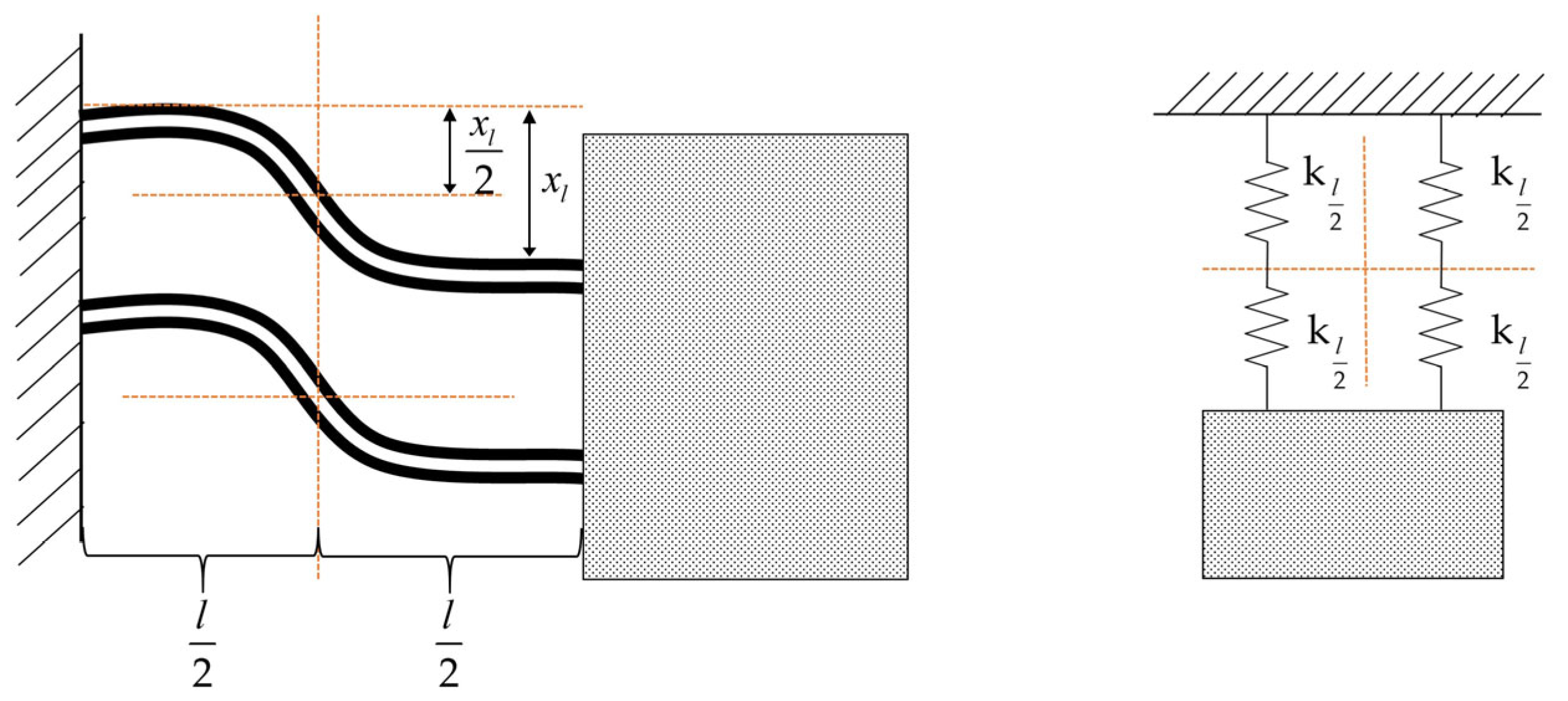
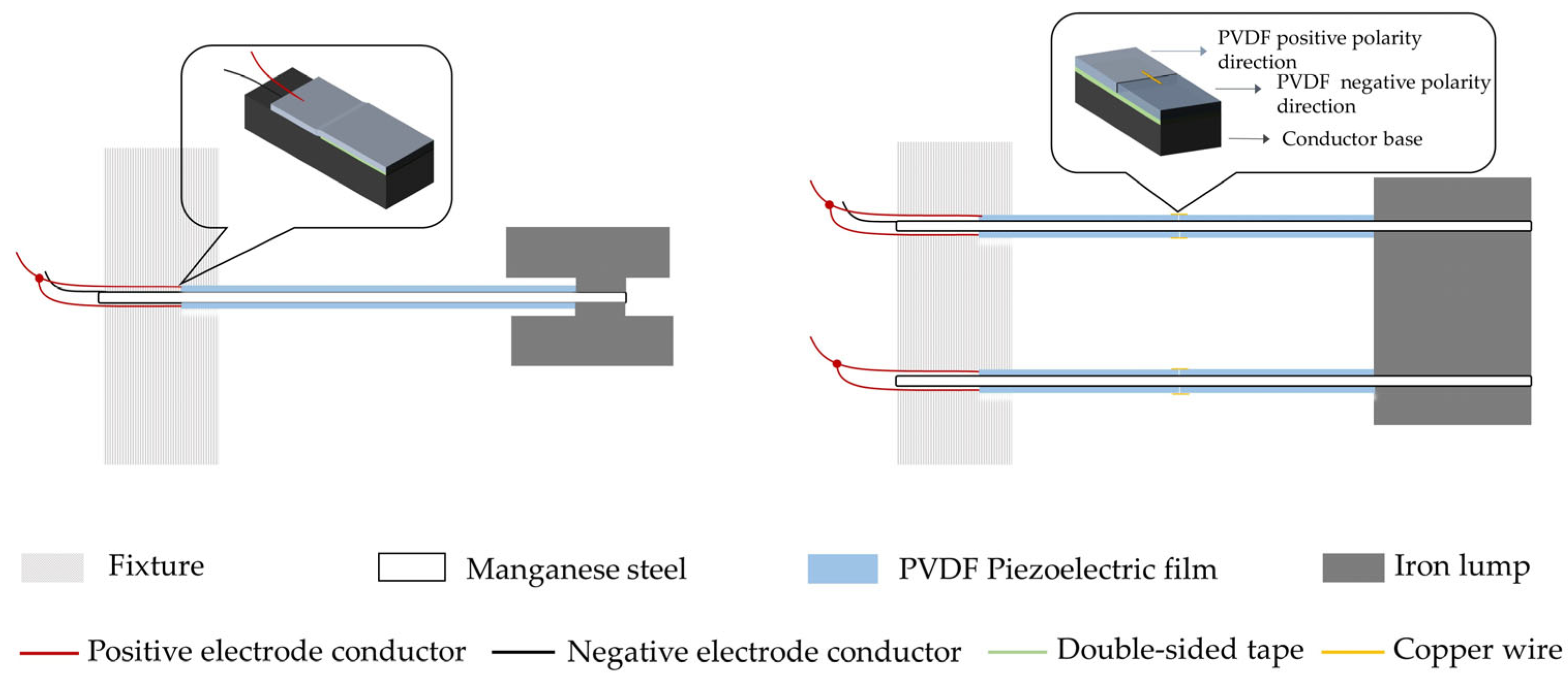
2.1. Mechanical Structure
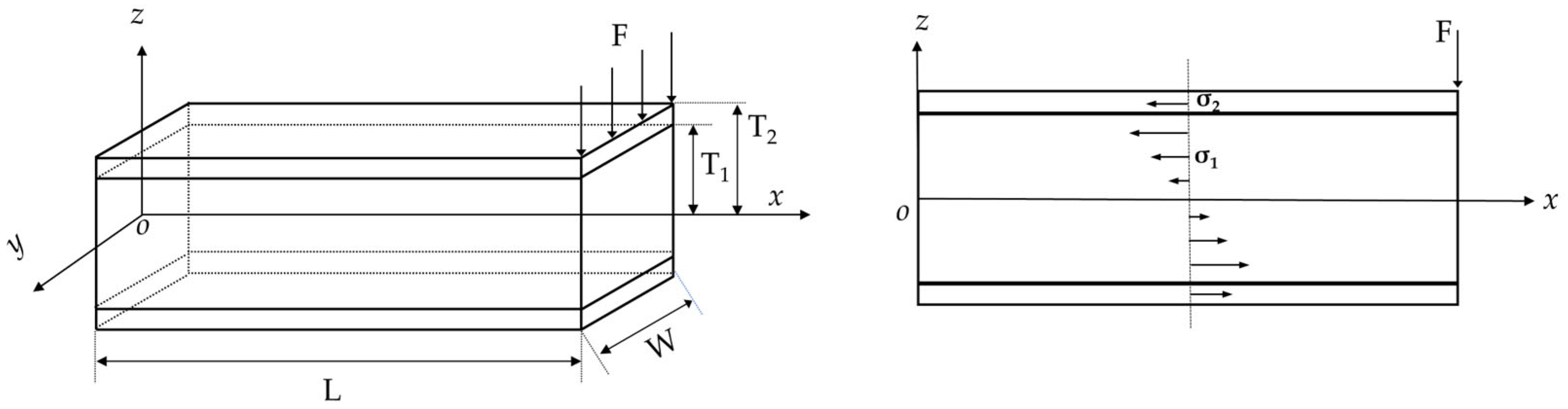
2.2. Piezoelectric Effect
2.3. Readout Circuit
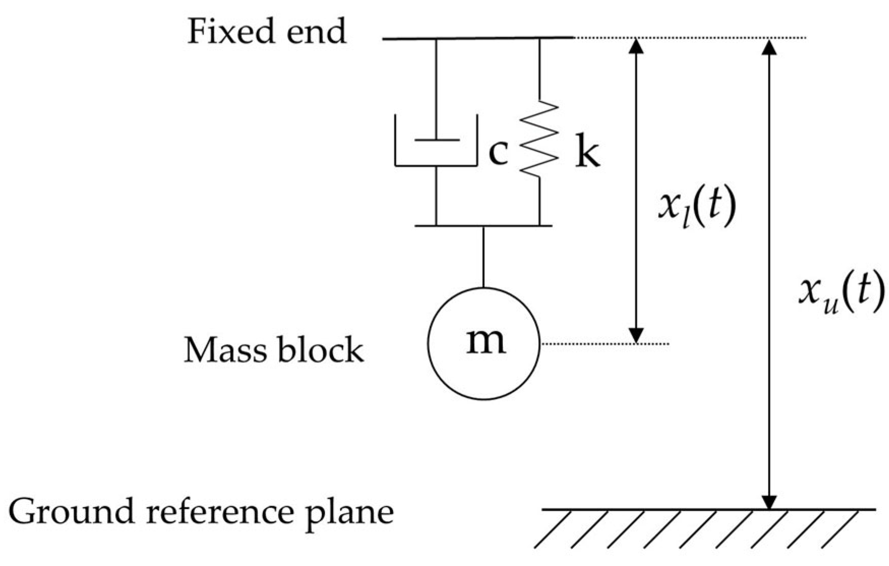
2.4. Transfer Function
2.5. Structural Parameter Design
3. Simulation Verification
3.1. Modal Simulation
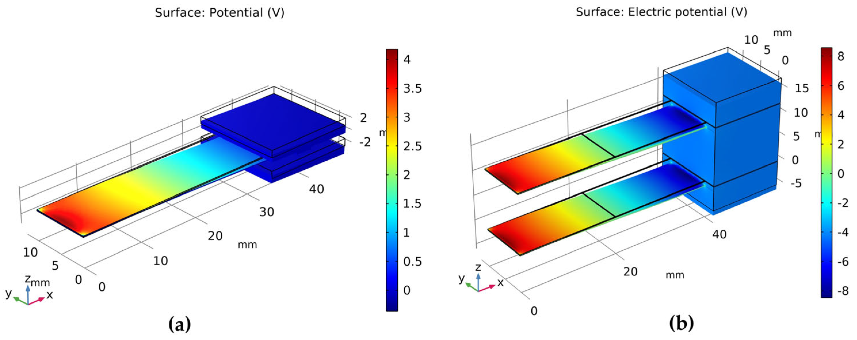
3.2. Steady-State Charge Simulation Comparison
3.3. Frequency Domain Analysis
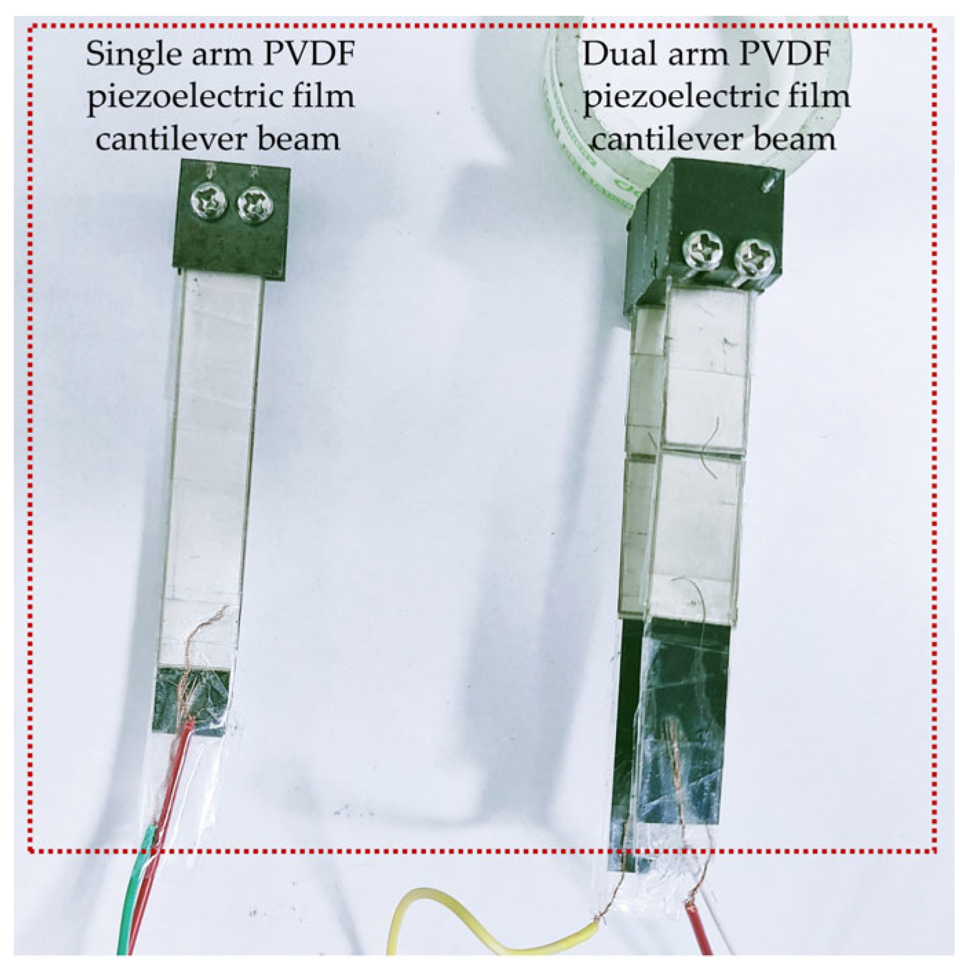
4. Fabrication
5. Experiment
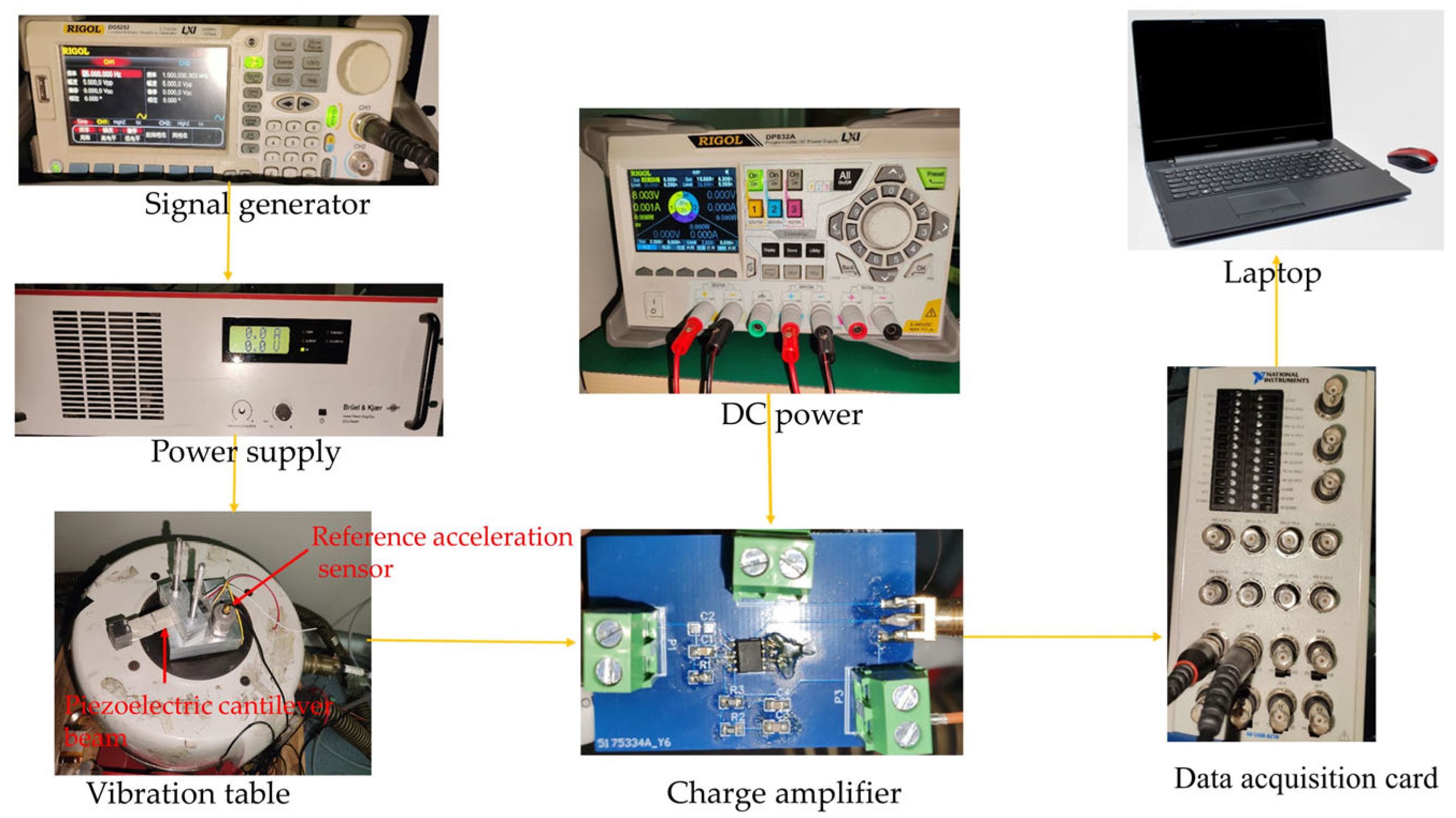
5.1. Test Platform
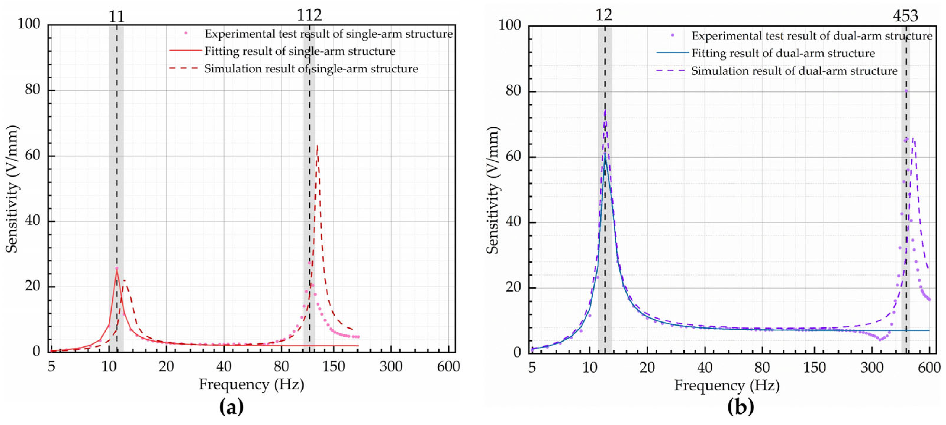
5.2. Test Results
6. Conclusions
Author Contributions
Funding
Data Availability Statement
Acknowledgments
Conflicts of Interest
References
- Shoaib, M.; Hamid, N.H.; Jan, M.T.; Ali, N.B.Z. Effects of crack faults on the dynamics of piezoelectric cantilever-based MEMS sensor. IEEE Sens. J. 2017, 17, 6279–6294. [Google Scholar] [CrossRef]
- Zhang, S.; Zhou, J.; Wang, E.; Zhang, H.; Gu, M. State of the art on vibration signal processing towards data-driven gear fault diagnosis. IET Collab. Intell. Manuf. 2022, 4, 249–266. [Google Scholar] [CrossRef]
- Yuan, Y.; Chen, H.; Xu, H.; Jin, Y.; Chen, G.; Zheng, W.; Wang, W.; Wang, Y.; Gao, L. Highly sensitive and wearable bionic piezoelectric sensor for human respiratory monitoring. Sens. Actuators A Phys. 2022, 345, 113818. [Google Scholar] [CrossRef]
- Mironov, A.; Safonovs, A.; Mironovs, D.; Doronkin, P.; Kuzmickis, V. Health Monitoring of Serial Structures Applying Piezoelectric Film Sensors and Modal Passport. Sensors 2023, 23, 1114. [Google Scholar] [CrossRef]
- Zhang, C.; Mousavi, A.A.; Masri, S.F.; Gholipour, G.; Yan, K.; Li, X. Vibration feature extraction using signal processing techniques for structural health monitoring: A review. Mech. Syst. 2022, 177, 109175. [Google Scholar]
- Wang, J.; Tong, Y.; Li, C.; Zhang, Z.; Shao, J. A Novel Vibration Piezoelectric Generator Based on Flexible Piezoelectric Film Composed of PZT and PI Layer. Polymers 2022, 14, 2871. [Google Scholar] [CrossRef]
- Zhong, M.; Long, Y.; Zhang, W.; Chen, Z.; Xie, Q. Multi-fractal analysis of the explosion seismic signal based on seismic exploration. In Proceedings of the 2009 First International Conference on Information Science and Engineering, Nanjing, China, 26–28 December 2009; IEEE: Piscataway, NJ, USA, 2009; pp. 600–603. [Google Scholar]
- Martini, A.; Rivola, A.; Troncossi, M. Autocorrelation analysis of vibro-acoustic signals measured in a test field for water leak detection. Appl. Sci. 2018, 8, 2450. [Google Scholar] [CrossRef]
- Bao, T.; Liu, Z. Vibration-based bridge scour detection: A review. Struct. Control Health Monit. 2017, 24, e1937. [Google Scholar]
- Kwon, Y.; Priest, E.; Gordis, J. Investigation of vibrational characteristics of composite beams with fluid–structure interaction. Compos. Struct. 2013, 105, 269–278. [Google Scholar] [CrossRef]
- Roy, P.; Ganesan, N. Transient response of a cantilever beam subjected to an impulse load. J. Sound Vib. 1995, 183, 873–880. [Google Scholar] [CrossRef]
- Zhao, Q.; Liu, Y.; Wang, L.; Yang, H.; Cao, D. Design method for piezoelectric cantilever beam structure under low frequency condition. Int. J. Pavement Res. Technol. 2018, 11, 153–159. [Google Scholar] [CrossRef]
- Lin, Y.-C.; Huang, Y.-H.; Ma, C.-C.; Chang, C.-K. Experimental and theoretical investigations on sensing and dynamic characteristics of PVDF thin film. J. Mech. 2020, 37, 1–12. [Google Scholar] [CrossRef]
- Mohammadpourfazeli, S.; Arash, S.; Ansari, A.; Yang, S.; Mallick, K.; Bagherzadeh, R. Future prospects and recent developments of polyvinylidene fluoride (PVDF) piezoelectric polymer; fabrication methods, structure, and electro-mechanical properties. RSC Adv. 2023, 13, 370–387. [Google Scholar] [CrossRef] [PubMed]
- Dallaev, R.; Pisarenko, T.; Sobola, D.; Orudzhev, F.; Ramazanov, S.; Trčka, T. Brief review of PVDF properties and applications potential. Polymers 2022, 14, 4793. [Google Scholar] [CrossRef] [PubMed]
- Hadimani, R.L.; Bayramol, D.V.; Sion, N.; Shah, T.; Qian, L.; Shi, S.; Siores, E. Continuous production of piezoelectric PVDF fibre for e-textile applications. Smart Mater. Struct. 2013, 22, 075017. [Google Scholar] [CrossRef]
- Xin, Y.; Sun, H.; Tian, H.; Guo, C.; Li, X.; Wang, S.; Wang, C. The use of polyvinylidene fluoride (PVDF) films as sensors for vibration measurement: A brief review. Ferroelectrics 2016, 502, 28–42. [Google Scholar] [CrossRef]
- Li, Y.; Xu, Y.; Zhu, J.; Liu, T.; Hou, T.; Liu, L.; Liu, H.; Xin, Y.; Lin, T. Design, assembly and testing of a novel piezoelectric geophone based on PVDF film. Integr. Ferroelectr. 2020, 211, 69–81. [Google Scholar] [CrossRef]
- Abdul, B.; Mastronardi, V.; Qualtieri, A.; Guido, F.; Algieri, L.; Rizzi, F.; De Vittorio, M. Design, fabrication and characterization of piezoelectric cantilever MEMS for underwater application. Micro Nano Eng. 2020, 7, 100050. [Google Scholar] [CrossRef]
- Singh, R.K.; Lye, S.W.; Miao, J. PVDF nanofiber sensor for vibration measurement in a string. Sensors 2019, 19, 3739. [Google Scholar] [CrossRef]
- Bhuvana, S.; Prathiksha, H.; Sindhu, V.; Vasudha, H. Design and analysis of piezoelectric cantilever based vibration sensor. In Proceedings of the 2018 IEEE International Conference on System, Computation, Automation and Networking (ICSCA), Pondicherry, India, 6–7 July 2018; IEEE: Piscataway, NJ, USA, 2018; pp. 1–6. [Google Scholar]
- Yi, J.; Liang, H. A PVDF-based deformation and motion sensor: Modeling and experiments. IEEE Sens. J. 2008, 8, 384–391. [Google Scholar]
- Chauhan, S.; Ansari, M.Z. Piezoelectric Cantilever Sensor Design with Improved Sensing and Self-actuation performance. IOP Conf. Ser. Mater. Sci. Eng. 2022, 1248, 012060. [Google Scholar] [CrossRef]
- Daku, B.L.; Mohamed, E.M.; Prugger, A.F. A PVDF transducer for low-frequency acceleration measurements. ISA Trans. 2004, 43, 319–328. [Google Scholar] [CrossRef]
- Rougeot, P.; Ousaid, A.M.; Gendreau, D.; Hammouche, M.; Rakotondrabe, M. Design, modeling and simulation of a three-layer piezoelectric cantilevered actuator with collocated sensor. In Proceedings of the SPIE Commercial + Scientific Sensing and Imaging, Sensors for Next-Generation Robotics III, Baltimore, MD, USA, 17–21 April 2016; pp. 139–150. [Google Scholar]
- Liu, M.; Xia, H.; Xia, D.; Liu, G. Research on frequency bandwidth and phase difference of piezoelectric resonant cantilever based on mass. Microsyst. Technol. 2021, 27, 3667–3677. [Google Scholar] [CrossRef]
- Sang, Y.; Fan, Y.; Wang, F.; Zhang, X.; Yang, Y.; Zhang, M. Vibration detection technology research based on piezoelectric cantilever. Mech. Adv. Mater. Struct. 2022, 29, 3588–3594. [Google Scholar] [CrossRef]
- Xu, Q.; Gao, A.; Li, Y.; Jin, Y. Design and optimization of piezoelectric cantilever beam vibration energy harvester. Micromachines 2022, 13, 675. [Google Scholar] [CrossRef] [PubMed]
- Wu, J.-J. Use of effective stiffness matrix for the free vibration analyses of a non-uniform cantilever beam carrying multiple two degree-of-freedom spring–damper–mass systems. Comput. Struct. 2003, 81, 2319–2330. [Google Scholar] [CrossRef]
- Gere, J.M.; Goodno, B.J. Mechanics of Materials; Cengage Learning: Boston, MA, USA, 2018; pp. 4–790. [Google Scholar]
- Kalimuldina, G.; Turdakyn, N.; Abay, I.; Medeubayev, A.; Nurpeissova, A.; Adair, D.; Bakenov, Z. A review of piezoelectric PVDF film by electrospinning and its applications. Sensors 2020, 20, 5214. [Google Scholar] [CrossRef]
- Abidin, N.A.K.Z.; Nayan, N.M.; Azizan, M.; Jamel, N.; Ali, A.; Azli, N.; Nordin, N. Performances of Multi-Configuration Piezoelectric Connection with AC-DC Converter in Low Frequency Energy Harvesting System. J. Phys. Conf. Ser. 2023, 2550, 012001. [Google Scholar] [CrossRef]
- Pinna, L.; Valle, M. Charge amplifier design methodology for PVDF-based tactile sensors. J. Circuits Syst. Comput. 2013, 22, 1350066. [Google Scholar] [CrossRef]


| Young’s Modulus (Pa) | Density (kg/m3) | Poisson Ratio | Relative Dielectric Constant | |
|---|---|---|---|---|
| Manganese steel | 198 × 109 | 7800 | 0.35 | / |
| PVDF | 2.8 × 10⁹ | 1780 | / | 13.5 |
| Iron | 198 × 109 | 7800 | 0.35 | / |
| Single-Arm Structure | Dual-Arm Structure | |
|---|---|---|
| Cantilever material | manganese steel | manganese steel |
| Cantilever length (mm) | 40 | 40 |
| Cantilever width (mm) | 10 | 10 |
| Base thickness (mm) | 0.15 | 0.15 |
| PVDF thickness (mm) | 0.028 | 0.028 |
| Arm distance (mm) | / | 12 |
| Block material | iron | iron |
| Block size (mm3) | 15 × 15 × 2.6 | 15 × 15 × 20.8 |
| Block mass (g) | 4.88 | 38.61 |
| First-Order Natural Frequency (Hz) | Generated Charge (C) by a 1 mm Relative Displacement | Voltage after Connecting Charge Amplifier (V) | |
|---|---|---|---|
| Single-arm structure | 11.7 | 5.78 × 10⁻⁹ | 1.9 |
| Dual-arm structure | 11.8 | 23.07 × 10⁻⁹ | 7 |
| Voltage (V) | Charge (C) | |
|---|---|---|
| Single-arm structure | 1.84 | 6.28 × 10⁻⁹ |
| Dual-arm structure | 3.68 | 25.13 × 10⁻⁹ |
| Structure | Theory | Simulation | Experiment | |
|---|---|---|---|---|
| First-order|Second-order natural frequency (Hz) | Single arm | 11.7|/ | 12.3|123.4 | 11|112 |
| Dual arm | 11.8|/ | 12|487.8 | 12.3|453 | |
| Sensitivity (V/mm) | Single arm | 1.75 | 1.90 | 2.05 |
| Dual arm | 7 | 7.62 | 7.12 |
| Measurement Band with ±20% Tolerance (Hz) | Ratio of Second-Order Natural Frequency to First-Order Natural Frequency | Sensitivity (V/mm) | Ratio of Dual-Arm Sensitivity to Single-Arm Sensitivity | |
|---|---|---|---|---|
| Single arm | 27–65 | 10.2 | 2.05 | —— |
| Dual arm | 29~280 | 36.8 | 7.12 | 3.48 |
Disclaimer/Publisher’s Note: The statements, opinions and data contained in all publications are solely those of the individual author(s) and contributor(s) and not of MDPI and/or the editor(s). MDPI and/or the editor(s) disclaim responsibility for any injury to people or property resulting from any ideas, methods, instructions or products referred to in the content. |
© 2023 by the authors. Licensee MDPI, Basel, Switzerland. This article is an open access article distributed under the terms and conditions of the Creative Commons Attribution (CC BY) license (https://creativecommons.org/licenses/by/4.0/).
Share and Cite
Xin, W.; He, Z.; Zhao, C. Design and Experimental Evaluation of a Dual-Cantilever Piezoelectric Film Sensor with a Broadband Response and High Sensitivity. Micromachines 2023, 14, 2108. https://doi.org/10.3390/mi14112108
Xin W, He Z, Zhao C. Design and Experimental Evaluation of a Dual-Cantilever Piezoelectric Film Sensor with a Broadband Response and High Sensitivity. Micromachines. 2023; 14(11):2108. https://doi.org/10.3390/mi14112108
Chicago/Turabian StyleXin, Wei, Zhaoyang He, and Chaocheng Zhao. 2023. "Design and Experimental Evaluation of a Dual-Cantilever Piezoelectric Film Sensor with a Broadband Response and High Sensitivity" Micromachines 14, no. 11: 2108. https://doi.org/10.3390/mi14112108
APA StyleXin, W., He, Z., & Zhao, C. (2023). Design and Experimental Evaluation of a Dual-Cantilever Piezoelectric Film Sensor with a Broadband Response and High Sensitivity. Micromachines, 14(11), 2108. https://doi.org/10.3390/mi14112108