

The Coupled Reactance-Less Memristor Based Relaxation Oscillators for Binary Oscillator Networks

Abstract
1. Introduction
2. The Behavior of Reactance-Less Memristor Based Oscillator
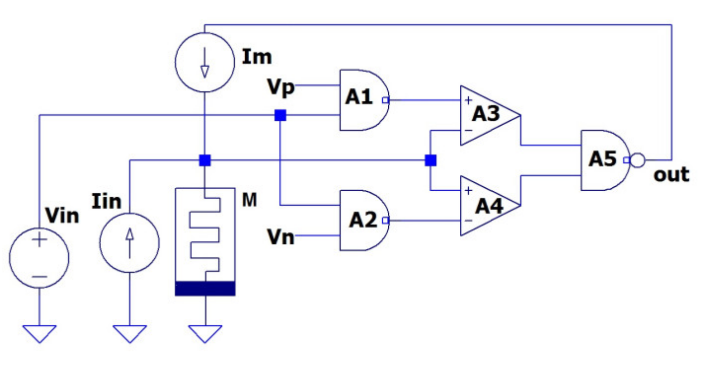
2.1. Operating Principles of Oscillator
2.2. Two Control Types in MBOs
3. Features of Coupled Reactance-Less Memristor Based Oscillators
- -
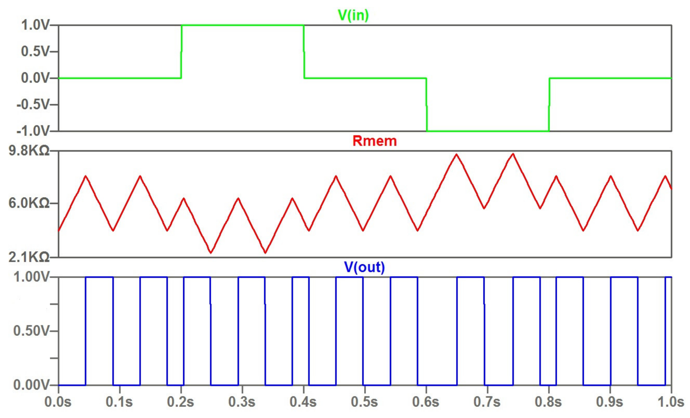
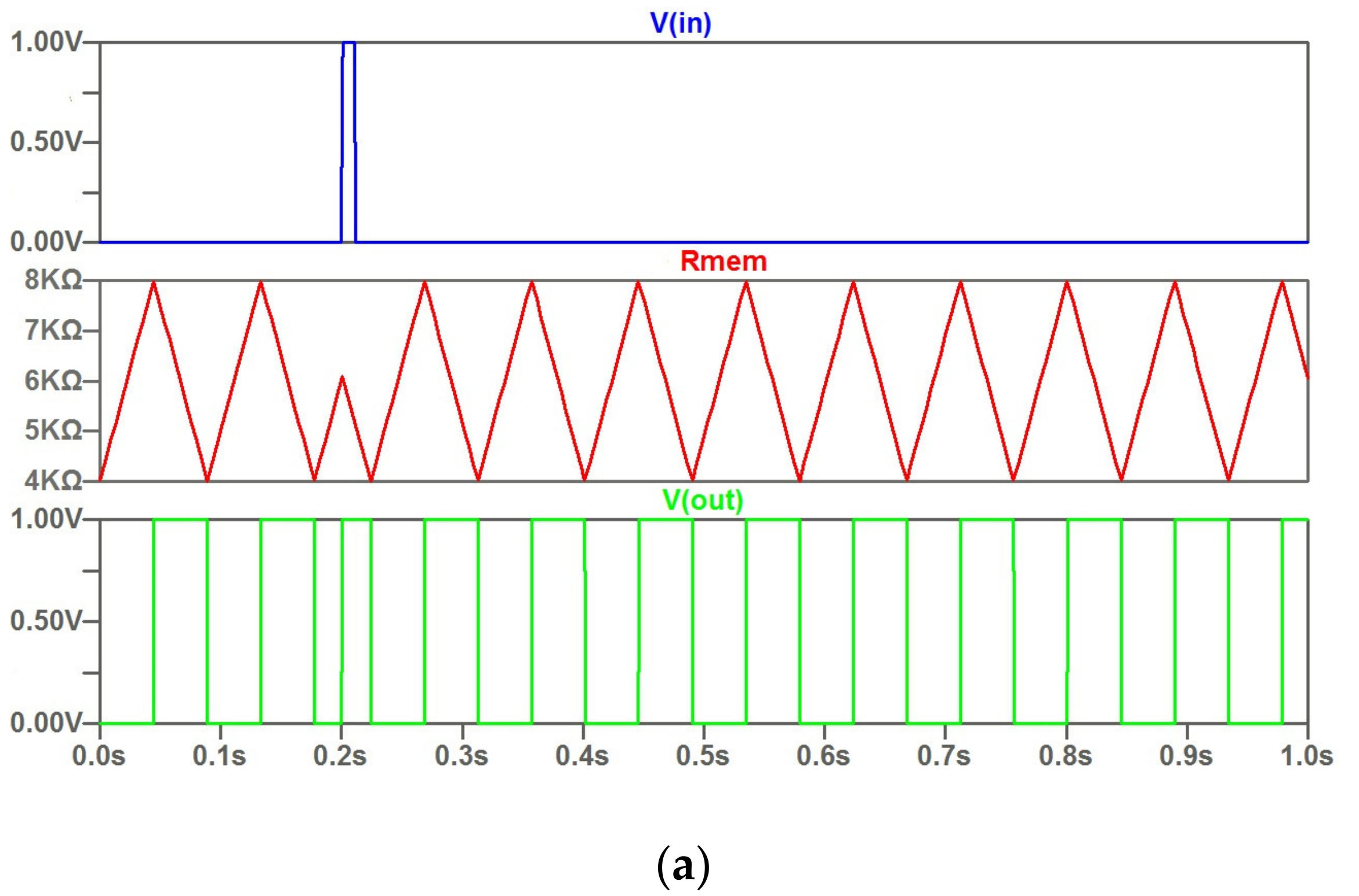
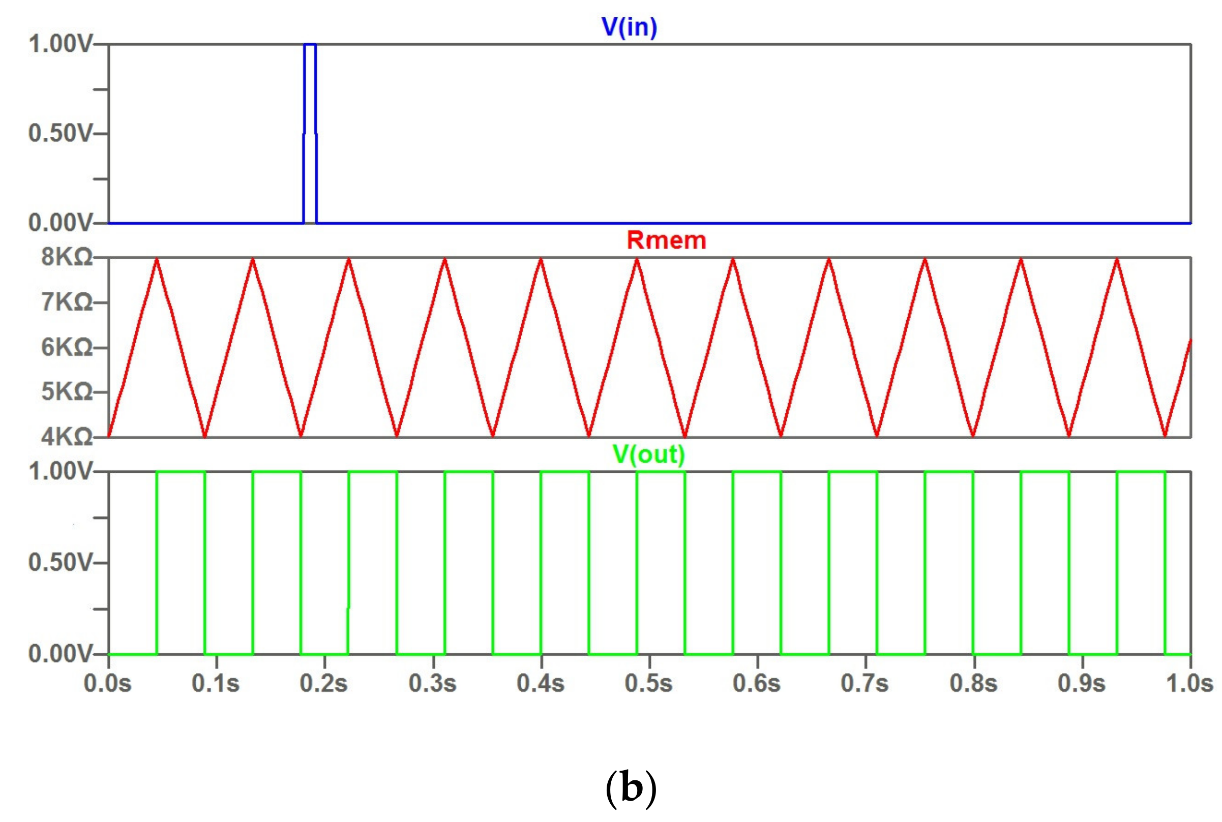
- During the action of the high output level (logical “1”) of the transmitting MBO, both comparator thresholds of the receiving MBO decrease; after the completion of the action of the high output level of the transmitting MBO, the comparator thresholds of the receiving MBO are restored to their original values. The low output level (logical “0”) of the transmitting MBO does not impact on the comparator thresholds of the receiving MBO;
- -
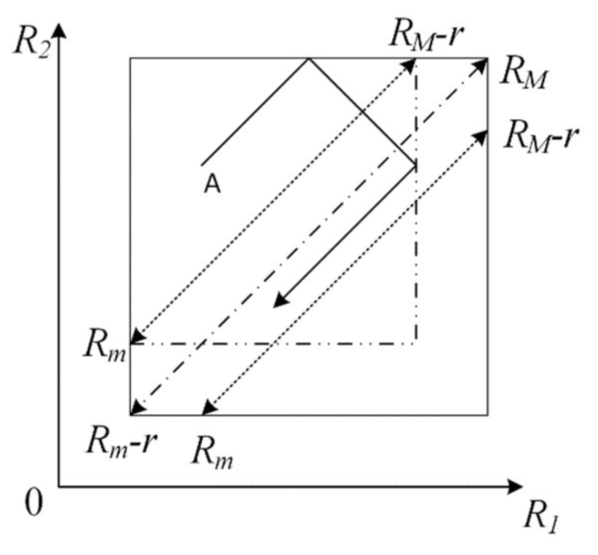
- Threshold changes are small enough to provide the condition of oscillations receiving MBO;
- -
- Input potential signal does not impact the amount of current flowing through the memristor.
4. Example of Application of Coupled MBOs in Oscillatory Networks
5. Conclusions
Author Contributions
Funding
Data Availability Statement
Conflicts of Interest
References
- Chua, L. Memristor-the missing circuit element. IEEE Trans. Circuit Theory 1971, 18, 507–519. [Google Scholar] [CrossRef]
- Strukov, D.B.; Snider, G.S.; Stewart, D.R.; Williams, R.S. The missing memristor found. Nature 2008, 453, 80–83. [Google Scholar] [CrossRef] [PubMed]
- Islam, R.; Li, H.; Chen, P.; Wan, W.; Chen, H.Y.; Gao, B. Device and Materials Requirements for Neuromorphic Computing. J. Phys. D Appl. Phys. 2019, 52, 113001. [Google Scholar] [CrossRef]
- Izhikevich, E.M. Dynamical Systems in Neuroscience: The Geometry of Excitability and Bursting; MIT Press: Cambridge, MA, USA, 2019; 441p. [Google Scholar]
- Huang, A.; Zhang, X.; Li, R.; Chi, Y. Memristor Neural Network Design. In Memristor and Memristive Neural Networks; James, A., Ed.; IntechOpen: London, UK, 2017. [Google Scholar] [CrossRef]
- Xu, W.; Wang, J.; Yan, X. Advances in Memristor-Based Neural Networks. Front. Nanotechnol. 2021, 3, 645995. [Google Scholar] [CrossRef]
- Itoh, M.; Chua, L.O. Memristor Oscillators. Int. J. Bifurc. Chaos 2008, 18, 3183–3206. [Google Scholar] [CrossRef]
- Radwan, A.G.; Fouda, M.E. On the Mathematical Modeling of Memristor, Memcapacitor, and Meminductor; Springer International Publishing: Cham, Switzerland, 2015. [Google Scholar] [CrossRef]
- Anjanakumari, T.; Bhoomika, C.M.; Jugale, A.A.; Ahmed, M.R. Memristor based Relaxation Oscillator for Biomedical applications. In Proceedings of the 3rd International Conference on Trends in Electronics and Informatics (ICOEI), Tirunelveli, India, 23–25 April 2019; pp. 1–5. [Google Scholar] [CrossRef]
- Ding, Y.; Yuan, P.; Yu, J.; Chen, Y. Forming-Free NbOx-Based Memristor Enabling Low-Energy-Consumption Artificial Spiking Afferent Nerves. IEEE Trans. Electron Devices 2022, 69, 5391–5394. [Google Scholar] [CrossRef]
- Zidan, M.; Omran, H.; Smith, C.; Syed, A.; Radwan, A.G.; Salama, K.N. Family of Memristor based Reactance less Oscillators. Int. J. Circuit Theory Appl. 2014, 42, 1103–1122. [Google Scholar] [CrossRef]
- Kyriakides, E.; Georgiou, J. A compact, low-frequency, memristor-based oscillator. Int. J. Circ. Theory Appl. 2015, 43, 1801–1806. [Google Scholar] [CrossRef]
- Fouda, M.E.; Radwan, A.G. Power Dissipation of Memristor-Based Relaxation Oscillators. Radioengineering 2015, 4, 968–973. [Google Scholar] [CrossRef]
- Rakitin, V.; Rusakov, S. Operating principles of reactance-less memristor-based oscillators. J. Commun. Technol. Electron. 2017, 62, 621–625. [Google Scholar] [CrossRef]
- Liang, Y.; Wang, S.; Dong, Y.; Lu, Z.; Wang, G. Locally-Active Memristors-Based Reactance-Less Oscillator. IEEE Trans. Circuits Syst. II Express Briefs 2023, 70, 321–325. [Google Scholar] [CrossRef]
- Chen, W.H.; Dou, C.; Li, K.-X.; Lin, W.-Y.; Li, P.-Y.; Huang, J.-H.; Chang, M.F. CMOS-integrated memristive non-volatile computing-in-memory for AI edge processors. Nat. Electron. 2019, 2, 420–428. [Google Scholar] [CrossRef]
- Wang, Y.; Wang, G.; Shen, I.H. A Memristor Neural Network Using Synaptic Plasticity and Its Associative Memory. Circuits Syst. Signal Process. 2020, 39, 1–16. [Google Scholar] [CrossRef]
- Secco, J.; Poggio, M.; Corinto, F. Supervised neural networks with memristor binary synapses. Int. J. Circuit Theory Appl. 2018, 46, 1–13. [Google Scholar] [CrossRef]
- Kim, H.; Sah, M.P.; Yang, C.; Roska, T.; Chua, L.O. Memristor Bridge Synapses. Proc. IEEE 2011, 100, 2061–2070. [Google Scholar] [CrossRef]
- Tsubone, T.; Saito, T. Manifold piecewise constant systems and chaos. IEICE Trans. Fundam. 1999, E82-A, 1619–1626. [Google Scholar]
- Yamashita, Y.; Torikai, H. Theoretical Analysis for Efficient Design of a Piecewise Constant Spiking Neuron Model. IEEE Trans. Circuits Syst. II Express Briefs 2014, 61, 54–58. [Google Scholar] [CrossRef]
- Rakitin, V.V.; Rusakov, S.G. Coupled Piecewise Constant Memristor based Reactance-less Oscillators. In Proceedings of the IEEE East-West Design and Test Symposium (EWDTS), Varna, Bulgaria, 4–7 September 2020; pp. 269–272. [Google Scholar] [CrossRef]
- Csaba, G.; Porod, W. Coupled oscillators for computing: A review and perspective. Appl. Phys. Rev. 2020, 7, 11302. [Google Scholar] [CrossRef]
- Raychowdhury, A.; Parihar, A.; Smith, G.H.; Narayanan, V.; Csaba, G.; Jerry, M.; Datta, S. Computing with networks of oscillatory dynamical systems. Proc. IEEE 2019, 107, 73–89. [Google Scholar] [CrossRef]
- Ascoli, A.; Weiher, M.; Herzig, M.; Slesazeck, S.; Mikolajick, T.; Tetzlaff, R. Graph Coloring via Locally-Active Memristor Oscillatory Networks. J. Low Power Electron. Appl. 2022, 12, 22. [Google Scholar] [CrossRef]
- Delacour, C.; Todri-Sanial, A. Mapping Hebbian Learning Rules to Coupling Resistances for Oscillatory Neural Networks. Front. Neurosci. 2021, 15, 694549. [Google Scholar] [CrossRef] [PubMed]
- Shamsi, J.; Avedillo, M.J.; Linares-Barranco, B.; Serrano-Gotarredona, T. Hardware Implementation of Differential Oscillatory Neural Networks Using VO2-Based Oscillators and Memristor-Bridge Circuits. Front. Neurosci. 2021, 15, 674567. [Google Scholar] [CrossRef] [PubMed]
- Perminov, V.V.; Putrolaynen, V.V.; Belyaev, M.A.; Velichko, A.A. Synchronization in the system of coupled oscillators based on VO2 switches. J. Phys. Conf. Ser. 2017, 929, 12045. [Google Scholar] [CrossRef]
- Nikonov, D.E.; Csaba, G.; Porod, W.; Shibata, T.; Voils, D.; Hammerstrom, D.; Bourianoff, G.I. Coupled-oscillator associative memory array operation for pattern recognition. IEEE J. Explor. Solid State Comput. Devices Circuits 2015, 1, 85–93. [Google Scholar] [CrossRef]
- Wang, W. Binary-oscillator Networks: Bridging a Gap Between Experimental and Abstract Modeling of Neural Networks. Neural Comput. 1996, 8, 319–339. [Google Scholar] [CrossRef] [PubMed]
- Biolek, Z.; Biolek, D.; Biolkova, V. SPICE model of memristor with nonlinear dopant drift. Radioengineering 2009, 18 Pt 2, 210–214. [Google Scholar]
- Rakitin, V.V.; Rusakov, S.G. Functional Capabilities of Coupled Memristor-Based Reactance-Less Oscillators. In Memristor: An Emerging Device for Post-Moore’s Computing and Applications; Chang., Y.-F., Ed.; IntechOpen: London, UK, 2021. [Google Scholar] [CrossRef]
- Corti, E.; Jimenez, J.A.C.; Niang, K.M.; Robertson, J.; Moselund, K.E.; Gotsmann, B.; Ionescu, A.M.; Karg, S. Coupled VO2 oscillators circuit as analog first layer filter in convolutional neural networks. Front. Neurosci. 2021, 15, 19. [Google Scholar] [CrossRef]
- Nikonov, E.; Kurahashi, P.; Ayers, J.S.; Lee, H.-J.; Fan, Y.; Young, I.A. Convolution Inference via Synchronization of a Coupled CMOS Oscillator Array. IEEE J. Explor. Solid-State Comput. Devices Circuits 2020, 6, 170–176. [Google Scholar] [CrossRef]


| Parameter | Description | Value |
|---|---|---|
| Ron | Resistance in ON State, [kOhm] | 1 |
| Roff | Resistance in OFF State, [kOhm] | 10 |
| Rinit | Initial resistance at t = 0, [kOhm] | 4 |
| uv | Migration coefficient, [m2 s−1 V−1] | 10−14 |
| D | Width of the thin film, [nm] | 10 |
| p | Parameter of the window function | 10 |
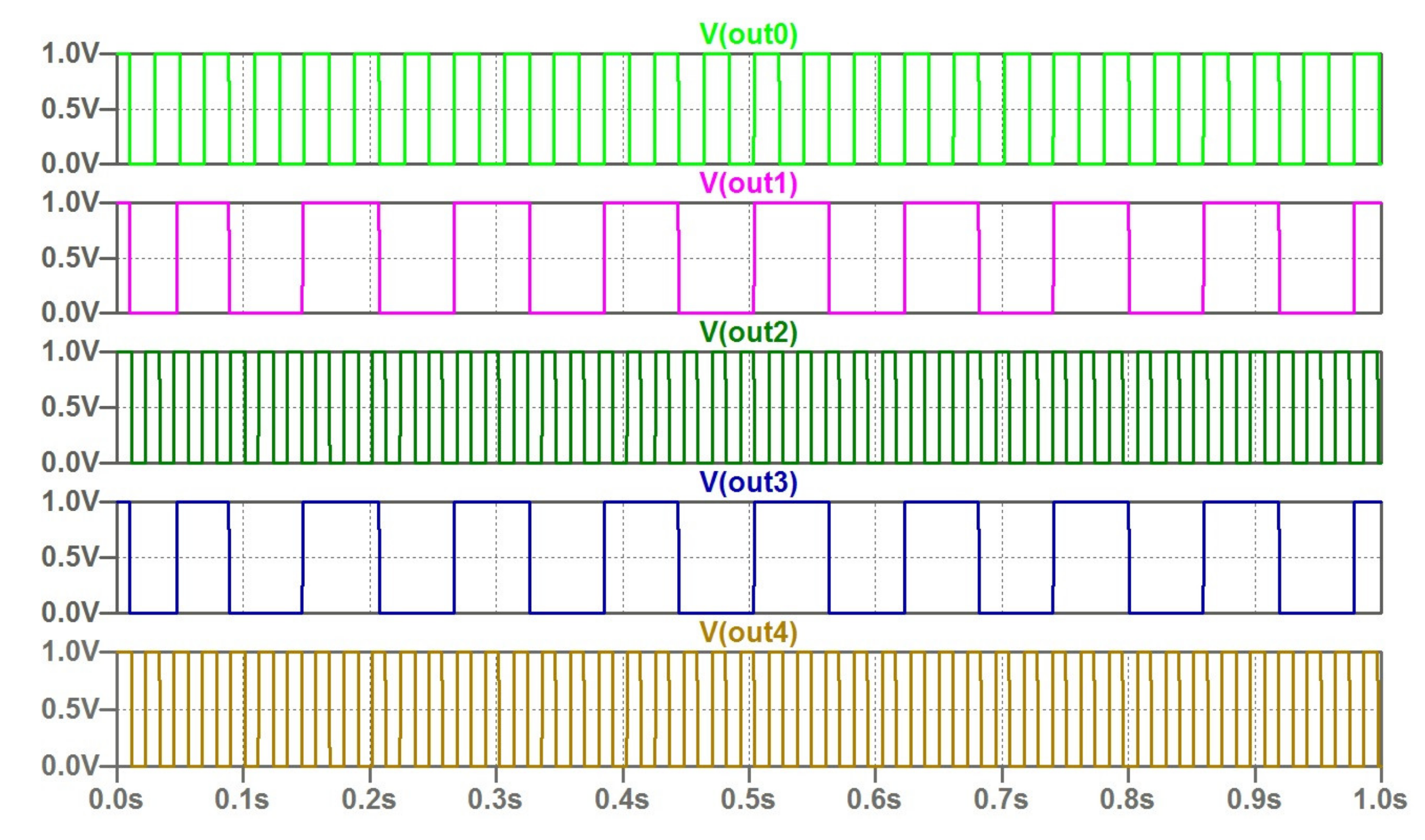
| White Im1 = 100 uA |
| Black Im2 = 200 uA |
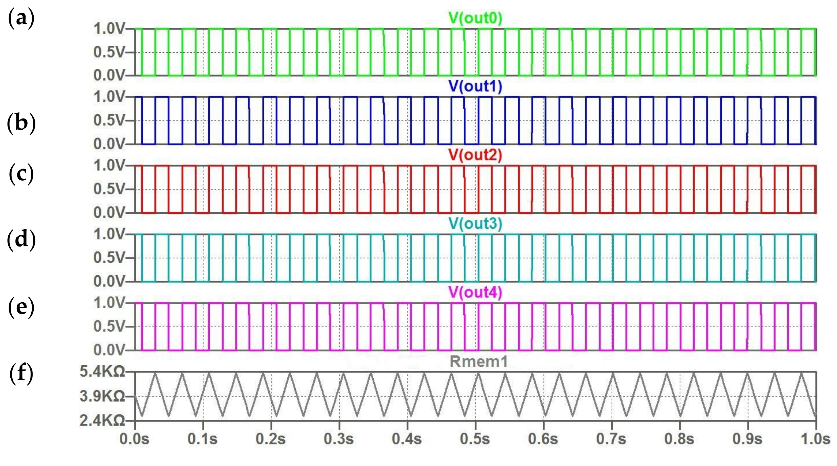
| White Im3 = 100 uA |
| Black Im4= 200 uA |
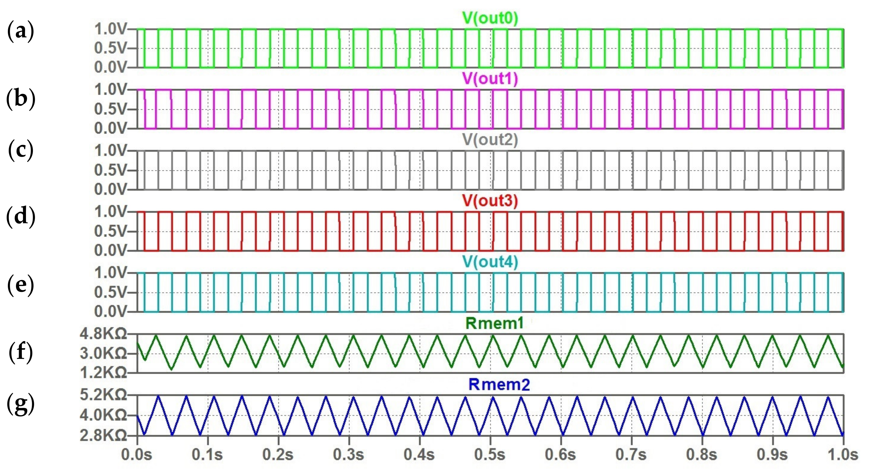
| Gray IM1 = 120 uA |
| Gray IM2 = 180 uA |
| White IM3 = 100 uA |
| Black IM4 = 200 uA |
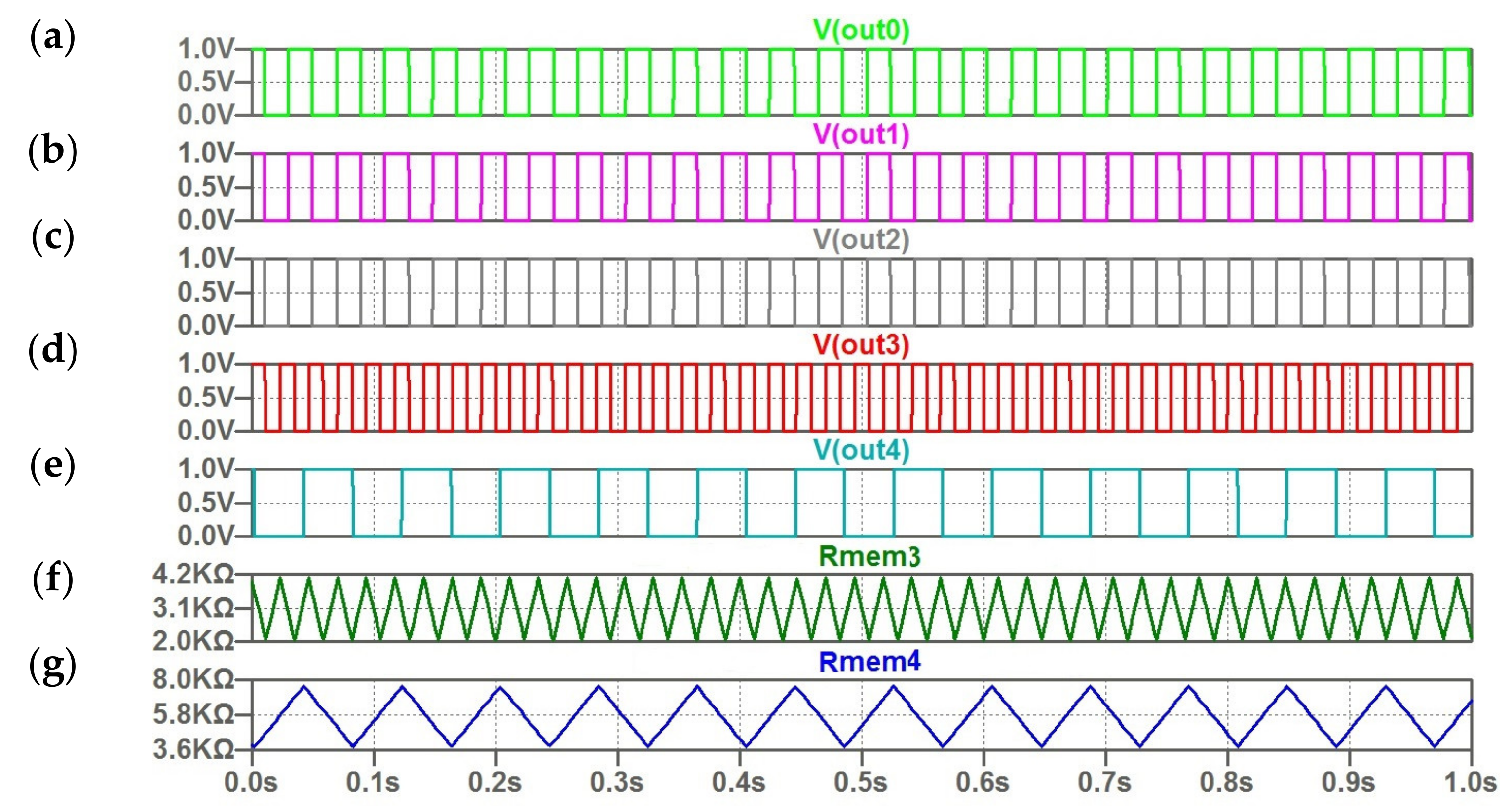
| White IM1 = 100 uA |
| Black IM2 = 200 uA |
| Gray IM3 = 145 uA |
| Gray IM4 = 155 uA |
Disclaimer/Publisher’s Note: The statements, opinions and data contained in all publications are solely those of the individual author(s) and contributor(s) and not of MDPI and/or the editor(s). MDPI and/or the editor(s) disclaim responsibility for any injury to people or property resulting from any ideas, methods, instructions or products referred to in the content. |
© 2023 by the authors. Licensee MDPI, Basel, Switzerland. This article is an open access article distributed under the terms and conditions of the Creative Commons Attribution (CC BY) license (https://creativecommons.org/licenses/by/4.0/).
Share and Cite
Rakitin, V.; Rusakov, S.; Ulyanov, S. The Coupled Reactance-Less Memristor Based Relaxation Oscillators for Binary Oscillator Networks. Micromachines 2023, 14, 365. https://doi.org/10.3390/mi14020365
Rakitin V, Rusakov S, Ulyanov S. The Coupled Reactance-Less Memristor Based Relaxation Oscillators for Binary Oscillator Networks. Micromachines. 2023; 14(2):365. https://doi.org/10.3390/mi14020365
Chicago/Turabian StyleRakitin, Vladimir, Sergey Rusakov, and Sergey Ulyanov. 2023. "The Coupled Reactance-Less Memristor Based Relaxation Oscillators for Binary Oscillator Networks" Micromachines 14, no. 2: 365. https://doi.org/10.3390/mi14020365
APA StyleRakitin, V., Rusakov, S., & Ulyanov, S. (2023). The Coupled Reactance-Less Memristor Based Relaxation Oscillators for Binary Oscillator Networks. Micromachines, 14(2), 365. https://doi.org/10.3390/mi14020365