Abstract
Designing new medical devices with advanced humidity sensors is of great significance for patients with incontinence-associated dermatitis (IAD). The primary goal of this study is to test the humidity-sensing mattress system for patients with IAD in clinical settings. The design of the mattress is set at 203 cm, with 10 × 3 sensors, dimensions of 19 × 32 cm, and a weighted bearing of 200 kg. The main sensors consist of a humidity-sensing film, a thin-film electrode (6 × 0.1 mm), and a glass substrate (500 nm). The sensitivity of the test mattress system showed that the resistance-humidity sensor was at a temperature of 35 °C ( = 30 V, = 350 mV), with slope at 1.13 V/fF, = 1 MHz, 20–90% RH, and a response time of 20 s at 2 m. In addition, the humidity sensor reached 90% RH, with a response time of less than 10 s, a magnitude of 1–1 , 1 mol%, , and F, respectively. This design is not only a simple, low-cost medical sensing device, but also opens a new pathway for developing humidity-sensing mattresses in the field of flexible sensors, wearable medical diagnostic devices, and health detection.
1. Introduction
Medical mattresses with advanced humidity sensors are receiving significant attention when it comes to treating patients with IAD [1,2,3]. Designing the humidity transducer so that it can detect an amount of water vapour (O) is one of the most important medical judgements and diagnoses. The recent development of humidity sensors for patients with IAD is gaining acceptance within medical devices [4,5,6]. Some scholars have developed a humidity sensor with inflammatory cytokines [7], skin temperature [8], metal oxide nanomaterials [9], transepidermal water [10], and water contact angle [11]. In the present designs, there has been a testing of mattresses which sense relative humidity (RH) in terms of resistance [5,12,13,14], film thickness [15], and the refractive index (RI) [16].
Humidity sensors for patients with IAD have been tested with moisture-associated dermatitis, liquid, and water vapour [1,8,10]. The humidity-sensors system has acquired water vapour consisting of highly reactive dipolar molecules, temperature, gaseous form, moisture, and liquid [1,6,9]. Previous studies have tested the humidity sensors’ design based on sensitivity, electro-active flow control devices, fast response, and low cost for sensing materials [4,17]. Many scholars have divided patients into three types when it comes to IAD-sensing devices: light, moderate, and heavy skin damage [18,19,20]. Humidity sensors are mainly based on impedance and resistance, including metal oxides [21], perovskites [22], and organic polymers [23].
Typically, the traditional design of humidity-sensing mattresses for patients with IAD has limitations, such as early IAD diagnosis [2,7]. Indeed, patients with IAD range from 5.3–46.1% in residential care and 19–54.7% for critically ill patients [24]. Previous scholars have tested the design of humidity sensors according to the clinical setting at 6% of moisture-associated skin damage in residential care [25]. Matar et al. [8] provided four types of sensing moisture-associated skin damage in IAD: erythema, localised swelling, vesicles, and crusting/scaling. The humidity sensor for IAD patients includes keeping the skin dry, maintaining pH balance, and offering moisturiser [26]. Despite this, mattresses using a flexible humidity sensor constitute one of the most essential medical devices, with examples being polymer film-based sensors [2], paper-based sensors [27], and flexible fibre-optic humidity sensors [28].
Thus, there still remains a lack of advanced humidity sensors which have been tested with patients exhibiting early signs of IAD. Indeed, the characteristics of sensing moisture-associated skin damage are limited, focusing on different types of sensing materials [1]. Previous studies have set dimensions of 10 × 5 cm to cut a point on the sensitive fibre-optic mattress [29]. A humidity sensor for IAD patients has the potential to increase the quality of devices, comfort, and sensitivity. The design includes using a thin firm electrode and glass substrate, which greatly tests the sensitivity of the humidity-sensing mattress for patients with IAD. Hence, the thin film electrode as an adhesion agent is reliable for mattress design but has not yet been applied to humidity sensors.
Accordingly, our study has designed a humidity-sensing mattress for patients with IAD following exposure to experimental testing in clinical settings. Firstly, the design of the mattress consists of a humidity-sensing film, a thin film electrode, and a glass substrate. Secondly, the design is also focused on the stability of the humidity sensors (RH, AB, and D/F PT), ambient temperature, and adsorption–desorption dynamic cycles. Finally, when testing the response time of 10–120 s with five volts, the magnitude ranged from 1–1 , and the pore ranged from 0–10 . The results of this study attest not only to humidity sensor designs for IAD patients but also the development of sensitive mattresses which can be developed in clinical settings.
2. Methods
2.1. Humidity-Sensing Design
When it comes to the sensing design of the mattress environmental chamber (MEC), it tests individual weight-loading support of 200 kg. The MEC consists of a lengthwise, zipped opening to allow mattress placement, as well as a loading array. The design of the testing mattress has a set of 203 cm × 96.5 cm peripheral outlets and a moisture-bearing patient moisture reservoir (PMR). The PMR rests on humidity sensors consisting of 0.28 (0.46 m × 0.6 m) polypropylene and a nominal total wet mass of 195 g (44 g dry). The water bladder measures approximately 0.43 (0.46 m × 0.91 m) and completely overlays the PMR. Figure 1 presents the humidity-sensing mattress design. The sensor region consists of two position areas as follows:
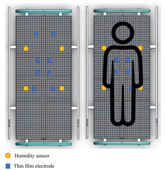
Figure 1.
Humidity-sensing mattress design.
- The humidity sensor is real-time monitoring of wetting moisture, water vapour, and vibration urine for converting the data into a corresponding electrical signal;
- The thin-film electrode array is a method for the fabrication of submicrometer gold on polyester and silicon. The sensor structure consists of a pair of interdigital electrodes and aluminium films on the glass substrate for the thickness (500 nm).
2.2. Humidity-Sensing Principle
A humidity sensor tests the amount of water vapour and temperature [1]. It is worth noting that a sensitive term encompasses (i) relative humidity (RH), absolute humidity (AH), parts per million (PPM), and the dew/frost point (D/F PT). The humidity sensor classifies the mass of water vapour, in grams per cubic metre, and feet (1 grain = pound (lb), as in the following equation:
where AH is the g/ or grain/, is the mass of water vapour, and is the volume of air (m3 or ft3). The RH is tested as the ratio of moisture to the maximum level, which gives the temperature and humidity. In the following, RH is equated as:
where . is the actual partial moisture and is the saturated temperature. It is known that saturation humidity (SH) is defined as:
where SH is the g/, is the mass of water vapour (g), and is the volume of air (). SH is the temperature in a unit volume of gas. RH calculates the ratio of AH to SH as follows:
The PPMv is defined as the volume of water vapour in dry gas, the PPMw refers to the water vapour. The PPMv and PPMw are amongst the AH, the D/F is based on the temperature (above 0 °C), and PT is the temperature (below 0 °C). However, the D/F point parameters are the AH.
The sensitivity of humidity is determined with the fixed capacity of voltage ( = + ), as follows:
The sensing sensitivity (S) is defined using the following equation:
where and represent the voltage of RH = 97% and RH = 11%. The S of humidity is approximately 29.9 mV/%RH.
Shimizu et al. [30] tested the field-effect transistor (FET) on host-PET devices and n-channel MISFET. The FET was set upper and lower on electrical connection with large resistance , whilst the outcome voltage, , was related to the capacity membrane, , as follows:
where is the load resistor to the electrode, is the transconductance of the PET, and is the voltage capacity of the gate insulator. Whilst is dependent on RH, is correlated with RH, the hysteresis is less than 3% RH, and there is a response time of 30 s. The capillary condensation of water vapour is cylindrical up to , as follows:
where is rious, , and represent the surface tension, density, and molecular weight of water, and represents vapour. Shimizu et al. [30] defined the simulation analysis in two actual porous ceramic elements, MgA and MgF. These elements are large parasites with a wide pore size in humidity using MgC for multifunctional sensors, which ranges from 20–90% RH, up to 150 °C, and with a response time of 10–120 s. The sensing elements are a tiny, porous, rectangular body of water containing MgC spinel solid solutions.
A porous sensor is based on additive and effective control (1 mol%), electrical conductivity, the pore size distribution, and response time (10 s). A pure MgF element is detected, with the addition of 2 mol % of , or over the whole range of RH. In response to the temperature, a semiconductor uses and . The electronic-type sensor was operated with voltage interferences of the elements with Pt/A.
2.3. Humidity-Sensing System
The humidity-sensing mattress is designed for clinical settings: 203 × 96.5 cm, 10 × 3 sensors, and a dimension of 19 × 32 cm [31]. The physical human, the size, material devices, and contact points are considered in the clinical design. The body anatomy includes the head, neck (occipital muscle), shoulders (right and left shoulders, main rhombic muscles), and lumbar spine. The main system consists of three regions: sensing block, processor block, and display block. The body-sensing positions are depicted in Figure 2. The humidity-sensing system is shown in Figure 3.
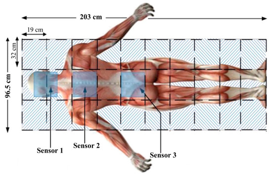
Figure 2.
Patient body sensing position.
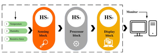
Figure 3.
Humidity-sensing system.
2.4. Humidity-Sensing Function
In the humidity-sensing mattress, the recording functions include system setup, data storage, graphing, and an alarm. Sensitivity is performed using a system calibration with preferences regarding the humidity sensor. Data storage is recorded as historical records and current data. The graphing function allows the patients and their caregivers to observe the recording. The sensor will present a signal on the screen if a hazard over the threshold is detected. The flowchart of the humidity-sensing system is shown in Figure 4, whilst the humidity-sensing diagram is illustrated in Figure 5. The electrode film and schematic drawing of the humidity sensor can be seen in Figure 6a,b.
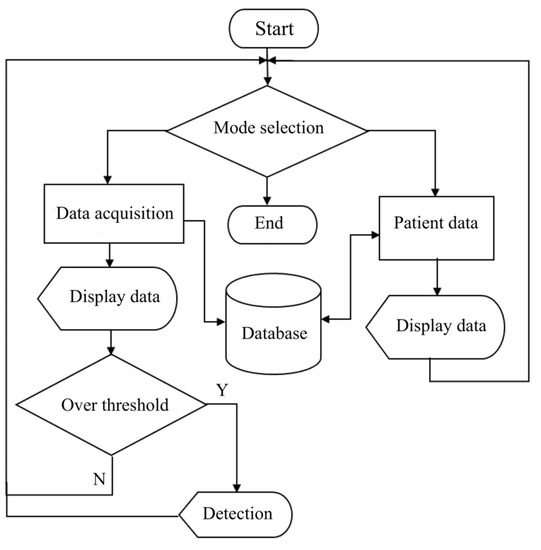
Figure 4.
Flowchart of humidity-sensing system.
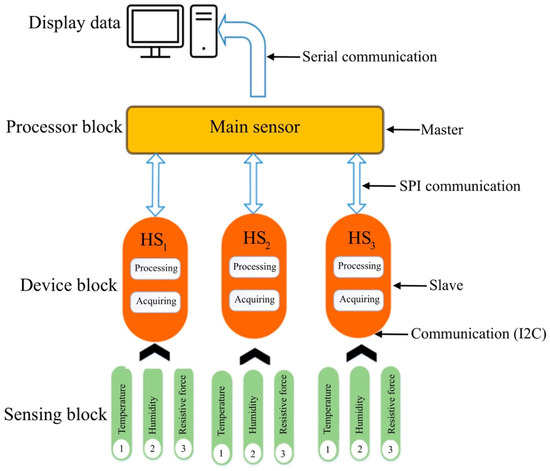
Figure 5.
Data flow of humidity-sensing block system processing diagram.
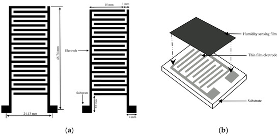
Figure 6.
(a) Humidity-sensing film; (b) Schematic drawing of the humidity sensor.
2.5. Humidity-Sensing System Platform
In the warm-up system, with regard to the humidity-sensing mattress platform, there is a connection between ScreenView and the processor (serial communication, temperature, and humidity value). The response time is set at 1 min at 100 Hz on Arduino technical data. Analogue inputs of the Arduino board are used to extract data at FSR400. The mapping of the contact point of the humidity-sensing platform is shown in Figure 7. Table 1 presents the working humidity-sensing system platform.
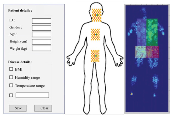
Figure 7.
Humidity-sensing system platform.

Table 1.
Humidity-sensing processing data platform.
2.6. Humidity-Sensing Volunteers
The testing of long-term bedridden patients with IAD is arranged with 19 volunteers of different temperature and humidity datasets. All volunteers are tested from the same number of patients with different values of BMI and pH index (see Table 2). To ensure testing accuracy, each volunteer is tested 10 times for 30 min in different body positions: lying, like side, supine, prone, and so on. In addition, the physical position of lying covers all three main areas that play a critical role in mattress contact. In this design, there are three effective contact points (ECP): occipital muscle, rhomboid major muscles, and spine endpoint. The testing sensor is initially put into standby mode for 1 min prior to each test, with ambient °C and RH being recorded. The humidity values have an arranged difference between °C and RH loading on the sensor datasets.
Table 2.
Volunteer data for the final humidity testing.
3. Results
3.1. Experimental Testing
A total of 19 voluntary patients with IAD underwent experimental testing at the Thammasat University Hospital, Thammasat University Rangsit Campus, Pathum Thani, Thailand. All patients provided informed consent to participate in the study. The Human Research Ethics Committee of Thammasat University (Science), Thailand, approved the study project in accordance with compliance with the Declaration of Helsinki, the Belmont Report, CIOMS guidelines, and international practice (ICH-GCP) (COA 032/2566 Project No. 66NU016). The body position regions consist of three sensors in patients with IAD: sensor 1 is the head and neck (occipital muscle), sensor 2 is the shoulders (rhomboid major muscles), and sensor 3 is the lumbar spine (spine endpoint), as can be seen in Figure 2 and Figure 7. The system starts by placing the 2.5 cm of thin film electrode without physical pressure (age, weight, and height) and temperature data are recorded as the initial value.
We designed the mattress so that it consists of a humidity sensor on the surface of the substrate and electrodes. A thin-film electrode is built on the glass substrate, which detects thickness at 500 mm. The length and width of the thin-film electrodes are approximately 0.1 mm, with two substracts (10 × 4 mm), as can be seen in Figure 6. The thickness of the layers is 15 m in vacuum circumstances at 380 °C for 1 h. The humidity sensor includes the 8-bit microcontroller for temperature outputting and humidity values as serial data. Table 3 depicts the RH of different saturated solutions, whilst Table 4 illustrates the average of HR changes for FSR and the force sensor. Table 5 presents the values of the physical force, temperature, and humidity sensors.
Table 3.
Different RH values.
Table 4.
Average humidity sensor.
Table 5.
Values of temperature and humidity sensors.
The experimental data show that SHT10, DS18B20, and FSR 400 are inputs, based on the mean values of the recorded data. The aqueous solutions of humidity sensors for long-term bedridden patients with IAD are set as LiCI, MgC, , Mg(N, NaCI, KCI, and S. The RH yields atmosphere values of 20–90%, which can be used to carry out an automatic RCL metre-PM. The testing frequency of humidity sensors varies from 50 Hz to 1 MHz in FSR sensors. The basis for the threshold comparison is an assumed mean water vapour mixing ratio of RH and sensor data. The threshold RH and humidity sensing assessment are shown in Table 6.
Table 6.
The comparison of threshold RH testing.
3.2. Voltage Sensitivity of RH Testing
This principal part of the sensor is nodulised under a vacuum ranging from 30–100 °C for 30 min, with the voltage signal of 0.85 V for the same RH change. The sensor resistance is extracted from 10 cycles, and the humidity is changed to 5% HR with a 10 s change ratio at a constant temperature of 35 °C. The resistance-humidity characteristics of the sensor are 35 °C, voltage (= 30 V, = 350 mV), RH from 10% to 80%, and response and recovery times of <10 s and <5 s, respectively. The humidity sensor is completely returned to the initial value when compared with recovery time and response time. This is due to the different RH dielectric constant water vapour threshold (>7.30), liquid (close to 80), and slope (1.13 V/fF), whilst changing from 50 to 70% HR. The voltage and power consumption range between 5 V and 6.5 mW, with RH ranging from 20–90% with 3.50 V from 1.03 V. Testing of the RH and voltage outcome is carried out as seen in Figure 8a,b.
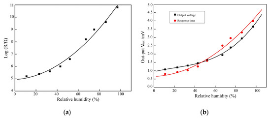
Figure 8.
(a) RH sensor testing; (b) Voltage outcome of sensors for RH testing.
3.3. Humidity-Sensing Stability Testing
The humidity-sensing conductance at different response times and recovery times is obtained from the HR. The conductance is set at = 100 Hz (0.10%), which tests 10 times at = 1 MHz. The repeatability is obtained from adsorption–desorption dynamic cycles ( = 1 MHz) with 20–90% RH. The humidity sensor shows that different parameters of RH are increasing and decreasing (ranging from 10%–70%). The response time (humidification ranges from 25–85.5%) is approximately 20 s, and the recovery time (desiccation ranges from 25–85.5%) is approximately 10 s. In the RH ranges from 20% to 90%, the data can be well fitted using the formula log C = 0.015 RH + 0.099 under the frequency of = 1 MHz. The sensor shows a maximum humidity hysteresis of 1.99%, corresponding to 90% RH. Table 7 depicts the characteristics of humidity-sensing repeatability.
Table 7.
Characteristics of the humidity sensor for repeatability testing.
The resistance humidity sensors show water vapour molecules of hydroxyl ions on the surface of the C sites. The porosity of MgC ranges from 30–40%, increasing by 1–2 m and 300 mm. The operated sensor is set at 35 °C as the formal desorption. The sensitivity shows that RH ranges from ~15–90% at 100 Hz. The humidity-sensing properties of magnesium ferrite (MgF) are based on ratios of lithium (MF) at 0.2 ≤ x ≤ 0.6. The repeated testing of 10 cycles shows good reversibility of humidity sensor switching between 20% and 90% RH with 20 s. The conductance variation from RH 20%–RH 95.5% at = 1 MHz is set at 20 cycles at 50 Hz; the stability sensor improves as the testing frequency increases. Figure 9 presents the stability of humidity sensors and conductance sensitivity.
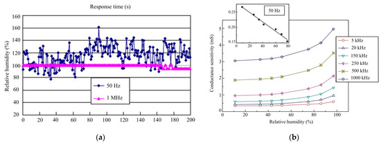
Figure 9.
(a) Stability of humidity-sensor testing; (b) Conductance sensitivity of RH testing.
3.4. Humidity-Sensing Performance Testing
The humidity-sensing performance testing is set at 35 °C, with a range of 20–90% RH. Three main humidity-sensor areas of patients with IAD (occipital muscle, rhomboid major muscles, and spine endpoint) are repeatedly tested with calibration changes at 0.5% RH, voltage (= 30 V, = 350 mV), = 1 MHz, and response time (20 s). The response time constant of the HR is 10 s with a five-volt voltage regulator and a DIN plug connector. The design of the testing humidity sensor produces an accuracy of ±2% RH at 35 °C, with ±0.8% of the threshold water vapour, and ±1% stability. There is a small RH effect of −0.22% RH/°C at 100 °C, decreasing to −0.07% RH/°C at 0% RH. The characteristics of humidity-sensing repeatability testing are depicted in Table 8.
Table 8.
Characteristics of humidity sensor repeatability testing.
The characteristics of the experimental testing range from 20–90% RH at 35 °C, producing faster response and recovery times of between 20 s and 60 s. The thin-film electrode sensors are set as and MgC, showing a good linear response to 90% RH with 10 s. The RH ranges from 25–85%, when combined with a sensitivity of 0.43%/HR% at 30 °C of 10 s. The resistance changes at a magnitude of 1 to 1 . The thick film indicated that nano-zirconium oxide (), a silicon substrate, a grain size of 20 nm, with a range of 25–85% RH, and a range of 50 Hz to 100 kHz. The testing of the humidity-sensing mattress illustrates a sensitivity of 1 mol% and F to , ranging from 25–95% RH with a pore size of 0.1 and a response time of 10 s. Figure 10 illustrates the RH measured in sensing mattress performance.
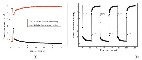
Figure 10.
(a) Response and recovery curve of humidity-sensor testing; (b) HR and conductance of = 1 MHz.
4. Discussion
This is the first study to develop a new sensing mattress for patients with IAD to test the humidity-sensor designs. The design is expected to serve as a sensing device in clinical settings, providing an objective database through which to validate humidity-sensor designs. The volunteer tests showed resistance-sensing humidity at 35 °C, a slope of 1.13 V/fF, and = 1 MHz with 20–90% RH. The sensors showed a response time of 20 s at 2 m, and 300 mm. Our repeatable sensitivity increased to −0.22% RH/°C at 100 °C, decreasing to −0.07% RH/°C at 0% RH. The characterisation of the humidity sensor designs showed a short response of 10 s, magnitude at 1–1 , 1 mol%, and , F, respectively. We found that resistance values of the different parameters were close to 37 °C (i.e., ±1 °C), with values in the range of 20–80% RH, and air velocity of 0.06–0.3 m/s.
The stability of the humidity values is also an important factor affecting the sensitivity of three main sensors: the occipital muscle, rhomboid major muscles, and spine endpoint (see Table 4 and Table 5). The highest frequency changes up to = 1 MHz were observed for three sensors of magnesium ferrite (MgF) on ratios of lithium (MF) at 0.2 ≤ x ≤ 0.6. It is clear that increasing to a 90% RH concentration results in a more viscous solution, which can serve as an effective humidity sensor (see Figure 8a,b). At the same time, we compared the humidity-sensing characteristics of three sensors at 100 kHz with a response time of 10 s, which has proven to be the best frequency from 25% RH–95% RH (see Figure 10a,b). As the result shows, a response time of 10 s with a five-volt voltage has a small amount of recovery time (the humidity difference at the same impedance value), which can effectively reduce the error of humidity sensors.
The sensing fitness of the resistant response of = 1 MHz is presented in Table 7 and Figure 10. Our experimental testing explained the humidity-sensing mechanism, as suggested in previous studies [1,4,5,11,13,26,32]. At higher frequencies, there was a change in humidity sensors because adsorbed water molecules cannot be polarised with a rapid change in clinical settings [16,33]. The repeatability test with increasing RH proves the suitability of patients with IAD in clinical settings. Therefore, we validated 100 kHz as the operating frequency in the following testing, related to previous studies [1,4,5,31,34]. With a variation of 20–90% RH, the change in five-volt voltage exhibited a relatively small pore size of 0.1 This means that, if a mattress is subjected to a high humidity change, it can be inconvenient and the sensing material of the humidity sensor is not good for patients with IAD in clinical settings [1,2,4,8,28].
Humidification was performed, with a value of 0.43%/HR% at 30 °C, a grain size of 20 nm, and a frequency between 100 Hz and 100 kHz. It was tested to be 0.5% when compared with the photon crystal fibre sensor of graphene oxide [35]. At low RH, a layer of the sensing pad of water molecules was adsorbed to form hydroxyl and sensing performance. Subsequently, as the humidity sensor increased, a layer of water molecules was adsorbed with double hydroxyl bonding. In bulk liquid, þ released to the adjacent water molecules and then cycled down to 0.5% RH, with a response time increase of 40 s and a recovery time of approximately 230 s. The low hysteresis in the sensor response was due to the highly hydrophobic structure of the thick film [36].
Response and recovery times constitute one of the significant features of the humidity-sensing mattress. The response time was tested by quickly moving the humidity sensor in a relatively dry environment (35% RH), which achieved 90% of the total impedance change. The sensitivity exhibited a fast response and a recovery time of between 10 s and 30 s, which is the best reported time for a resistive type of humidity-sensing mattress for IAD in clinical settings [24,32,37]. A sputtered metal oxide film (1.2 ) acted as both an RH and a piezoelectric actuation layer for the electrode. Yang et al. [38], Bian et al. [39] and Chu et al. [40] fabricated humidity sensors using response times of 0.701 nm/RH% and 2.728 nm/RH%, ranging between 30 °C and 110 °C for = −1 m. The repeatable sensing mattress is based on humidity, perhaps showing a slight response of 50 nm, but there was a noticeably slower recovery (>600 ms) at 35 °C and a rate of 0.8% HR per minute.
5. Conclusions
In conclusion, the design of the humidity-sensing mattress has been tested with regard to the water vapour with RH, AB, PPM, and D/F PT. The testing showed resistance-humidity characteristics of the sensor at 35 °C ( = 30 V, = 350 mV), the slope at 1.13 V/fF, = 1 MHz with 20–90% RH, a response time of 20 s at 2 m, and 300 mm. Repeatable sensitivity demonstrated that the humidity sensor increased to 0.22% RH/°C at 100 °C, and decreased to −0.07% RH/°C at 0.5% RH. The conductivity range was 30% RH with 10 s, a magnitude of 1–1 , 1 mol%, and and F, respectively. Further, the feasible humidity sensor integrated into the water vapour was tested by embedding that sensor in the thin-film electrode. The repeatable humidity sensor has many advantages, with a response time of less than 10 s, whilst the addition of 2 mol % of can greatly improve the sensitivity over the whole range of RH.
The development of the humidity-sensing mattress is a crucial step in the production of a novel piece of medical technology that provides a faster response, high sensitivity, and recovery time; indeed, it may also be a potential design for practical application. Notably, the design of the humidity-sensing mattress compounded with the thin-film electrode as the RH increased to 90%, showing excellent sensitivity. This property enables the sensor to be applied to medical diagnosis for patients with IAD. When the design has been applied, and the enhanced clinical acceptance of sensing material is a reality, it will be possible to provide and develop a low-cost mattress for IAD in clinical homecare. Once available, this humidity-sensing mattress has broad application prospects in the field of flexible sensors, wearable medical diagnostic devices, health detection, etc.
Author Contributions
Conceptualisation, J.M., P.R., C.M. and B.R.; software, J.M., P.R., C.M. and B.R.; validation, J.M., P.R., C.M. and B.R.; formal analysis, J.M., P.R., C.M. and B.R.; data curation, J.M., P.R., C.M. and B.R.; writing—original draft preparation, J.M., P.R., C.M. and B.R.; writing—review and editing, J.M., P.R., C.M. and B.R.; project administration, J.M.; funding acquisition, J.M. All authors have read and agreed to the published version of the manuscript.
Funding
This work (Grant No. RGNS 65–104) was financially supported by the Office of the Permanent Secretary, Ministry of Higher Education, Science, Research and Innovation.
Data Availability Statement
MDPI Research Data Policies.
Conflicts of Interest
The authors declare no conflict of interest.
References
- Duan, Z.; Jiang, Y.; Tai, H. Recent advances in humidity sensors for human body related humidity detection. J. Mater. Chem. C 2021, 9, 14963–14980. [Google Scholar] [CrossRef]
- Owen, E.J.; Heylen, R.A.; Stewart, K.; Winyard, P.G.; Jenkins, A.T. Detecting and monitoring incontinence associated dermatitis: Does impedance spectroscopy have a part to play? Proc. Inst. Mech. Eng. Part H-J. Eng. Med. 2023, 09544119231159178. [Google Scholar] [CrossRef] [PubMed]
- Omotunde, M.; Wagg, A. Technological solutions for urinary continence care delivery for older adults: A scoping review. J. Wound Ostomy Cont. Nurs. 2023, 50, 227–234. [Google Scholar] [CrossRef] [PubMed]
- Tekcin, M.; Sayar, E.; Yalcin, M.K.; Bahadir, S.K. Wearable and flexible humidity sensor integrated to disposable diapers for wetness monitoring and urinary incontinence. Electronics 2022, 11, 1025. [Google Scholar] [CrossRef]
- Mamom, J.; Rungroungdouyboon, B.; Daovisan, H.; Sri-Ngernyuang, C. Electronic alert signal for early detection of tissue injuries in patients: An innovative pressure sensor mattress. Diagnostics 2023, 13, 145. [Google Scholar] [CrossRef]
- Jeong, G.; Park, S. Review of urinary continence care products using sensor technology to improve effectiveness. Proc. Inst. Mech. Eng. Part H-J. Eng. Med. 2019, 233, 91–99. [Google Scholar] [CrossRef]
- Koudounas, S.; Bader, D.L.; Voegeli, D. Investigating the release of inflammatory cytokines in a human model of incontinence-associated dermatitis. J. Tissue Viability 2021, 30, 427–433. [Google Scholar] [CrossRef]
- Matar, H.; Larner, J.; Viegas, V.; Kansagra, S.; Atkinson, K.L.; Shetage, S.; Skamarauskas, J.T.; Theivendran, B.; Goldman, V.S.; Chilcott, R.P. Evaluation of a new topical skin protectant (RD1433) for the prevention and treatment of incontinence-associated dermatitis. Cutan. Ocul. Toxicol. 2017, 36, 211–219. [Google Scholar] [CrossRef]
- Sikarwar, S.; Yadav, B.C. Opto-electronic humidity sensor: A review. Sens. Actuator A Phys. 2015, 233, 54–70. [Google Scholar] [CrossRef]
- Larner, J.; Matar, H.; Goldman, V.S.; Chilcott, R.P. Development of a cumulative irritation model for incontinence-associated dermatitis. Arch. Dermatol. Res. 2015, 307, 39–48. [Google Scholar] [CrossRef]
- Khan, A.; Huang, K.; Hu, M.; Yu, X.; Yang, D. Wetting behavior of metal-catalyzed chemical vapor deposition-grown one-dimensional cubic-SiC nanostructures. Langmuir 2018, 34, 5214–5224. [Google Scholar] [CrossRef] [PubMed]
- McNichol, L.L.; Ayello, E.A.; Phearman, L.A.; Pezzella, P.A.; Culver, E.A. Incontinence-associated dermatitis: State of the science and knowledge translation. Adv. Ski. Wound Care 2018, 31, 502–513. [Google Scholar] [CrossRef] [PubMed]
- Zhao, J.; Li, N.; Yu, H.; Wei, Z.; Liao, M.; Chen, P.; Wang, S.; Shi, D.; Sun, Q.; Zhang, G. Highly sensitive MoS2 humidity sensors array for noncontact sensation. Adv. Mater. 2017, 29, 1702076. [Google Scholar] [CrossRef]
- Mamom, J.; Rungroungdouyboon, B.; Chuanasa, J. Enhancing the quality of long-term patient care by use of the innovative “electrical bed-turning system” for the prevention of pressure injuries: A pilot study. Sci. Technol. Asia 2022, 27, 128–135. [Google Scholar]
- Tripathy, A.; Pramanik, S.; Cho, J.; Santhosh, J.; Abu Osman, N.A. Role of morphological structure, doping, and coating of different materials in the sensing characteristics of humidity sensors. Sensors 2014, 14, 16343–16422. [Google Scholar] [CrossRef]
- Ahsani, V.; Ahmed, F.; Jun, M.B.G.; Bradley, C. Tapered fiber-optic mach-zehnder interferometer for ultra-high sensitivity measurement of refractive index. Sensors 2019, 19, 1652. [Google Scholar] [CrossRef]
- Khan, A.; Habib, M.R.; Kumar, R.R.; Islam, S.M.; Arivazhagan, V.; Salman, M.; Yang, D.; Yu, X. Wetting behaviors and applications of metal-catalyzed CVD grown graphene. J. Mater. Chem. A 2018, 6, 22437–22464. [Google Scholar] [CrossRef]
- Gray, M. Optimal management of incontinence-associated dermatitis in the elderly. Am. J. Clin. Dermatol. 2010, 11, 201–210. [Google Scholar] [CrossRef]
- Lv, C.; Hu, C.; Luo, J.; Liu, S.; Qiao, Y.; Zhang, Z.; Song, J.; Shi, Y.; Cai, J.; Watanabe, A. recent advances in graphene-based humidity sensors. Nanomaterials 2019, 9, 422. [Google Scholar] [CrossRef]
- Wu, Z.; Yang, J.; Sun, X.; Wu, Y.; Wang, L.; Meng, G.; Kuang, D.; Guo, X.; Qu, W.; Du, B.; et al. An excellent impedance-type humidity sensor based on halide perovskite CsPbBr3 nanoparticles for human respiration monitoring. Sens. Actuators B Chem. 2021, 337, 129772. [Google Scholar] [CrossRef]
- Tomer, V.K.; Duhan, S. In-situ synthesis of SnO2/SBA-15 hybrid nanocomposite as highly efficient humidity sensor. Sens. Actuators B Chem. 2015, 212, 517–525. [Google Scholar] [CrossRef]
- Cho, M.Y.; Kim, S.; Kim, I.S.; Kim, E.S.; Wang, Z.J.; Kim, N.Y.; Kim, S.W.; Oh, J.M. Perovskite-induced ultrasensitive and highly stable humidity sensor systems prepared by aerosol deposition at room temperature. Adv. Funct. Mater. 2020, 30, 1907449. [Google Scholar] [CrossRef]
- Dai, J.X.; Zhang, T.; Zhao, H.R.; Fei, T. Preparation of organic-inorganic hybrid polymers and their humidity sensing properties. Sens. Actuators B Chem. 2017, 242, 1108–1114. [Google Scholar] [CrossRef]
- Mugita, Y.; Minematsu, T.; Huang, L.; Nakagami, G.; Kishi, C.; Ichikawa, Y.; Nagase, T.; Oe, M.; Noguchi, H.; Mori, T.; et al. Histopathology of incontinence-associated skin lesions: Inner tissue damage due to invasion of proteolytic enzymes and bacteria in macerated rat skin. PLoS ONE 2015, 10, e0138117. [Google Scholar] [CrossRef]
- Bardsley, A. Prevention and management of incontinence- associated dermatitis. Nurs. Stand. 2013, 27, 41–46. [Google Scholar] [CrossRef]
- Han, P.; Li, L.; Zhang, H.; Guan, L.; Marques, C.; Savović, S.; Ortega, B.; Min, R.; Li, X. Low-cost plastic optical fiber sensor embedded in mattress for sleep performance monitoring. Opt. Fiber Technol. 2021, 64, 102541. [Google Scholar] [CrossRef]
- Li, L.; Ke, Y.; Zhang, T.; Zhao, J.; Huang, Z. A human defecation prediction method based on multi-domain features and improved support vector machine. Symmetry 2022, 14, 1763. [Google Scholar] [CrossRef]
- Bao, W.; Chen, F.; Lai, H.; Liu, S.; Wang, Y. Wearable breath monitoring based on a flexible fiber-optic humidity sensor. Sens. Actuators B Chem. 2021, 349, 130794. [Google Scholar] [CrossRef]
- Wang, S.; Ni, X.; Li, L.; Wang, J.; Liu, Q.; Yan, Z.; Zhang, L.; Sun, Q. Noninvasive monitoring of vital signs based on highly sensitive fiber optic mattress. IEEE Sens. J. 2020, 20, 6182–6190. [Google Scholar] [CrossRef]
- Shimizu, Y.; Arai, H.; Seiyama, T. Theoretical studies on the impedance-humidity characteristics of ceramic humidity sensors. Sens. Actuat. 1985, 7, 11–22. [Google Scholar] [CrossRef]
- Kuo, T.B.; Li, J.Y.; Lai, C.T.; Huang, Y.C.; Hsu, Y.C.; Yang, C.C. The effect of bedding system selected by manual muscle testing on sleep-related cardiovascular functions. Biomed. Res. Int. 2013, 2013, 937986. [Google Scholar] [CrossRef] [PubMed]
- Mamom, J.; Daovisan, H. Repositioning mattress: How a lateral tilt position reshapes the prevention of pressure ulcers in bedridden patients. J. Med. Eng. Technol. 2022, 46, 658–669. [Google Scholar] [CrossRef] [PubMed]
- Ascorbe, J.; Corres, J.M.; Arregui, F.J.; Matias, I.R. Recent developments in fiber optics humidity sensors. Sensors 2017, 17, 893. [Google Scholar] [CrossRef] [PubMed]
- Zhao, J.; Yu, Z.; Tu, Z.; Bian, H. Influence of electrode structure on performance of laser direct writing Cu-PI flexible humidity sensor. Micromachines 2022, 13, 992. [Google Scholar] [CrossRef] [PubMed]
- Li, J.X.; Tong, Z.R.; Jing, L.; Zhang, W.H.; Qin, J.; Liu, J.W. Fiber temperature and humidity sensor based on photonic crystal fiber coated with graphene oxide. Opt. Commun. 2020, 467, 125707. [Google Scholar] [CrossRef]
- Hammouche, H.; Achour, H.; Makhlouf, S.; Chaouchi, A.; Laghrouche, M. A comparative study of capacitive humidity sensor based on keratin film, keratin/graphene oxide, and keratin/carbon fibers. Sens. Actuator A Phys. 2021, 329, 112805. [Google Scholar] [CrossRef]
- Wang, N.; Tian, W.; Zhang, H.; Yu, X.; Yin, X.; Du, Y.; Li, D. An Easily Fabricated High Performance Fabry-Perot Optical Fiber Humidity Sensor Filled with Graphene Quantum Dots. Sensors 2021, 21, 806. [Google Scholar] [CrossRef]
- Yang, J.; Guan, C.; Yu, Z.; Yang, M.; Shi, J.; Wang, P.; Yang, J.; Yuan, L. High sensitivity humidity sensor based on gelatin coated side-polished in-fiber directional coupler. Sens. Actuators B Chem. 2020, 305, 127555. [Google Scholar] [CrossRef]
- Bian, C.; Wang, J.; Bai, X.; Hu, M.; Gang, T. Optical fiber based on humidity sensor with improved sensitivity for monitoring applications. Opt. Laser Technol. 2020, 130, 106342. [Google Scholar] [CrossRef]
- Chu, R.; Guan, C.; Bo, Y.; Shi, J.; Zhu, Z.; Li, P.; Yang, J.; Yuan, L. All-optical graphene-oxide humidity sensor based on a side-polished symmetrical twin-core fiber Michelson interferometer. Sens. Actuators B Chem. 2019, 284, 623–627. [Google Scholar] [CrossRef]


Disclaimer/Publisher’s Note: The statements, opinions and data contained in all publications are solely those of the individual author(s) and contributor(s) and not of MDPI and/or the editor(s). MDPI and/or the editor(s) disclaim responsibility for any injury to people or property resulting from any ideas, methods, instructions or products referred to in the content. |
© 2023 by the authors. Licensee MDPI, Basel, Switzerland. This article is an open access article distributed under the terms and conditions of the Creative Commons Attribution (CC BY) license (https://creativecommons.org/licenses/by/4.0/).