4.1. Ar Flow Impact on Removal Function
Owing to the high molecular bonding energy of CF4, relatively high power is required for ionization to produce a stable plasma. To continuously excite CF4, it is typically passed into a stable plasma environment, and the violent motion of electrons in the excited state of the plasma collides with the CF4 molecules to ionize CF4 and produce active F particles. Ar was selected owing to its cost-effectiveness and widespread availability compared to other inert gases.
During the processing, although Ar does not directly participate in the plasma chemical reaction, its flow rate plays a crucial role in determining the overall gas flow rate and the characteristics of the plasma jet’s exit, including the flow state and concentration of active particles. Consequently, the Ar flow rate is a significant factor that influences the removal rate in plasma processing. In this experiment, the effect of the Ar flow rate on the removal function was investigated to understand its impact.
The prerequisite for conducting the experiments was maintaining a stable plasma jet state. When the Ar flow rate is too low, the plasma jet becomes weak and may struggle to efficiently excite the plasma. Conversely, when the Ar flow rate is too high, it can disrupt the plasma jet and compromise the uniformity of the discharge. The plasma torch can produce a stable plasma jet in the range of an Ar flow rate of 15–27 SLM. Under the experimental parameters shown in
Table 1, the experiment was divided into six levels with Ar flow rates of 15, 17, 19, 21, 23, 25, and 27 SLM, with the other parameters fixed, and a point dwell was performed on the wafer surface to investigate the variation law of the removal function.
The experimental results are presented in
Figure 6. The Ar flow rate has a small effect on the
FWHM of the removal function, and the peak removal rate
a decreased with increasing Ar flow rate, whereas the volume removal rate
V was affected by both the
FWHM of the removal function and the peak removal rate
a, which also decreased gradually with increasing Ar flow rate. The observed decrease in the peak removal rate and volume removal rate with increasing Ar flow rate can be attributed to the need to maintain a stable plasma jet state. To prevent the plasma jet from ceasing owing to the “avalanche effect” after the introduction of CF
4 and O
2, a sufficient or excessive incoming Ar flux is often utilized to ensure the excitation of enough gas. In the experiments, when the Ar flow rate was relatively low, the green color of the plasma jet was darker, indicating a higher concentration of active F particles in the jet. Therefore, the peak removal rate
a and volume removal rate
V of the removal function were also larger. However, as the Ar flow rate continued to increase, the jet color gradually became lighter, suggesting an increasing excess of Ar and a subsequent reduction in the concentration of CF
4-excited active F particles. A lower concentration of active F particles leads to a decrease in the peak removal rate
a and, consequently, a decrease in the volume removal rate
V.
4.2. CF4 Flow Impact on Removal Function
The essence of plasma etching of SiC wafers is to remove the wafer surface material using the chemical reaction between the reactive F particles in the plasma jet and the silicon carbide surface. CF
4 excitation to generate reactive F particles in the reaction gas is the core of plasma processing. The CF
4 flow rate is the key factor in determining the concentration of reactive F particles within the plasma jet. The effect of different CF
4 flow rates on the removal function was examined by varying the CF
4 flow rates while keeping other parameters constant. The CF4 flow rates investigated in the experiments were 0, 15, 25, 35, 45, 55, 65, 75, and 85 SCCM, as shown in
Table 2. The experimental results are illustrated in
Figure 7.
As can be seen from
Figure 7, the plasma jet does not etch the SiC wafer when the reaction gas CF
4 is not passed inside the excited gas, indicating that active F particles are necessary for the plasma etching provided by CF
4.
When the CF4 flow rate was <65 SCCM, the FWHM of the removal function did not change significantly and fluctuated at a fixed value, whereas the peak removal rate a and peak removal rate V increased with the flow rate. This is because the CF4 flow rate was very low, nearly one-thousandth of the Ar flow rate. Although the CF4 flow rate gradually increased, the total flow rate of the gas excited to produce the plasma was basically constant, resulting in a constant flow field and FWHM. As the flow rate of the reaction gas gradually increased, the concentration of active F particles increased. This, in turn, promoted the chemical reaction rate between the plasma and the surface of the SiC. Consequently, the peak removal rate a of the removal function increase and obtains a higher volume removal rate V.
However, when the CF4 flow rate continues to increase, the FWHM and volume removal rate V of the removal function gradually decreases, and the rate of increase in the peak removal rate a decreases. CF4 poses challenges in direct excitation by the electric field to form plasma. Furthermore, CF4 itself does not undergo chemical reactions with SiC material. Consequently, high CF4 flow rates can affect the plasma atmosphere generated by Ar and narrow the plasma discharge range, thereby limiting the excitation of CF4. Therefore, the FWHM decreases in the removal function, causing the volume removal rate V to decrease.
Therefore, the volume removal rate V of the plasma jet was maximum at an input power of 500 W, Ar flow rate of 19 SLM, and CF4 flow rate of approximately 65 SCCM.
4.3. O2 Flow Impact on Removal Function
O
2 is not directly involved in the chemical reaction of the etched silicon carbide material during processing; however, the passage of an appropriate amount of O
2 can enhance the processing rate of plasma-etched SiC while simultaneously reducing the deposit generation. Single-factor experiments were conducted using the test parameters listed in
Table 3 to study the effect of O
2 flow rate on the removal function, with experimental results shown in
Figure 8.
As shown in
Figure 8, when the plasma was excited by auxiliary gas O
2 below 20 SCCM, the peak removal rate,
a, and volume removal rate,
V, of the process removal function were lower than those of the plasma excited by Ar and CF
4 only. This indicates that the inhibitory effect of O
2 on the active F particle production was greater than the generation effect when the incoming O
2 flow rate was lower than 20 SCCM. The peak removal rate,
a, and
FWHM of the removal function increased significantly, and the volume removal rate,
V, increased when the O
2 flux was gradually increased. The volume removal rate,
V, was the largest at a rate of 40 SCCM O
2, which was more than twice the volume removal rate,
V, without O
2.
It can be found that the removal function and the volume removal rate,
V, are similar between O
2 flow rates of 20 and 0 SCCM. The plasma processing spot removal profile bus diagram on the surface of the SiC wafer under the two process parameters was observed separately, as shown in
Figure 9. The maximum processing diameters of the two processing spots are close to each other at approximately 4 mm. The two processing spots were examined separately using a super-depth-of-field microscope, and the results are shown in
Figure 10.
Among them,
Figure 10a presents the detection map of the plasma processing spot without the introduction of O
2 auxiliary gas. The presence of a distinct circular layer of white deposition surrounding the processing spot around the center is clearly evident in the figure. The visible deposition range is approximately 7.5 mm in diameter, which is much larger than the actual processing spot removal diameter. Furthermore, the white deposition deteriorates the surface roughness of the wafer, which requires removal by a subsequent fine polishing process.
Figure 10b shows the processing spot detection when 20 SCCM of O
2 was applied. The deposition is significantly reduced, and the overall deposition circle with the processing center as the origin is approximately 6.8 mm in diameter. Moreover, the visible deposition range is approximately 0.7 mm smaller than the deposition range formed when the auxiliary gas O
2 is not introduced. The amount of deposition was significantly reduced inside the ring. A comparison between the two graphs reveals that the introduction of O
2 in the working gas has a significant impact. It reduces the extent of deposition and minimizes the formation of large white deposits caused by the etching reaction. This leads to an improvement in the surface quality of the processed workpiece and a reduction in the time required for fine polishing. Overall, the inclusion of O
2 enhances the processing efficiency of SiC wafers.
This can be attributed to the reaction of O with particles such as CF2, CF3, and COF generated by CF4 within the plasma. This reaction gives rise to compounds such as COF2 and OF*. Notably, OF* readily decomposes to produce F*, increasing the number of active F particles and promoting the chemical reaction rate. However, the deposits were mainly due to the large number of sedimentary particles generated after CF4 is ionized, such as CF, CF2, CF3, etc. These fluorocarbons reach the workpiece surface with the plasma jet and combine with the Si ions in the material to form polymeric macromolecules attached to the workpiece surface, which block further etching by active F particles. The incoming O reacts with all three particles, which inhibits the generation of deposits and improves the etching efficiency. However, because O must consume the F atoms in the plasma when reacting with the generated COF2 particles, the etching reaction was inhibited to some extent. Therefore, it is necessary to control the O2 flow rate and experimentally determine a suitable O2 flow rate range.
Observation of the plasma jet morphology during processing showed that when the incoming O
2 flow rate increased to 20 SCCM, the plasma jet shape started to become thinner and narrower, and the visible length of the jet decreased. Additionally, the color gradually became lighter, from green to white, as shown in
Figure 11. According to
Figure 8b, the
a of the removal function continues to increase rapidly, indicating that the effective processing distance of the plasma jet far exceeds the visible jet length; that is, the effective action distance of the active particles is much larger than the visible jet length.
When the O2 flow rate exceeds 40 SCCM, the peak removal rate of the removal function rises at a slower rate. The FWHM fluctuates at a fixed value, and the volume removal rate remains relatively constant. However, it is observed that the plasma jet starts to flicker or even extinguish. This indicates that an increase in the O2 flow rate causes plasma instability. Therefore, careful control of the O2 flow rate is necessary during processing to maintain stable plasma conditions.
4.4. Effect of Processing Power on Removal Function
Processing power is the magnitude of the power supplied to both ends of the induction coil by the RF power supply during plasma processing. It serves as the energy source for the plasma system and plays a crucial role in determining the effectiveness of the processing. The maintenance of plasma is dependent on the continuous oscillation collision of electrons in the excited state with gas molecules so that the compound ionization process occurs continuously in the plasma. However, because electrons gradually lose energy during the collision process with gas molecules, the RF power supply is needed to continuously excite new electrons to continue the reaction.
The effect of machining power on the removal function was experimentally studied by varying machining power in the 350–650 W range with a step size of 50 W and other experimental parameters, as listed in
Table 4.
The experimental results shown in
Figure 12 indicate that the
FWHM, peak removal rate, and volume removal rate of the removal function all increase linearly with an increase in processing power, and the changes are significant. In the case of an adequate supply of processing gas, an increase in machining power results in higher energy input to the plasma. This leads to an increase in electron density within the plasma, which in turn excites more CF
4 gas and raises the concentration of active F particles. As a result, the peak removal rate (
a) of the removal function increases. Additionally, the increase in electron energy expands the diffusion range of active F particles, leading to an increase in the
FWHM of the removal function. Thus, the relationship between machining power and the removal function is characterized by an increase in both the peak removal rate (a) and the
FWHM as machining power increases.
The processing power input to an RF power supply cannot be increased indefinitely. During the experiments, when a power of 700 W was used to excite the plasma for processing the SiC wafer, it resulted in the wafer breaking. It was observed that variations in the processing parameters led to differences in the temperature of the plasma generated by excitation. The plasma temperature is an important factor that affects the etching rate of the plasma. The available literature and preliminary experimental studies show that processing power plays a decisive role in determining the magnitude of the plasma temperature [
20]. Studies show that the plasma temperature increases linearly with power, and the higher the processing power, the faster the plasma temperature increases. A higher processing power can increase the temperature of the chemical reaction between the active F particles and silicon carbide, promoting the rate of the etching reaction. Consequently, this reduces the processing time for removing surface and subsurface damage. Conversely, a smaller processing power can reduce the temperature of the plasma and reduce the deformation of the wafer material due to heat. Therefore, in actual processing, the relationship between the material removal rate and plasma temperature should be balanced and the processing power optimized.
4.5. Effect of Processing Distance on Removal Function
From a macroscopic perspective, a plasma jet can be likened to a fluid. As it emerges from the nozzle, the jet initiates a divergence, becoming more pronounced as it moves away from the nozzle. Generally, the distance from the plasma torch nozzle to the workpiece surface is referred to as the processing distance. The experiments were conducted at a processing power of 500 W, and the processing distances were varied and set to 3, 4, 5, 6, and 7 mm, with other experimental parameters held constant, as shown in
Table 5.
The experimental results are shown in
Figure 13. The larger the processing distance between the nozzle and the SiC wafer, the smaller the peak removal rate of the removal function. It was observed that this relationship is not strictly linear. When the machining distance increased from 3 to 5 mm, the
FWHM of the removal function did not change significantly, and the volume removal rate decreased gradually. However, when the machining distance increased to 6 mm, the
FWHM and volume removal rate decreased sharply; when the machining distance increased to 7 mm, the
FWHM and volume removal rate did not change substantially. This indicates that as the processing distance increased, the degree of jet dispersion increased, resulting in a relative decrease in the number of active F particles diffused to the surface by the jet. In the experimental setup conducted in an atmospheric environment, it was observed that once the plasma jet exits the nozzle and interacts with the surrounding air, the active particles within the plasma collide with the neutral gas molecules in the air, resulting in energy loss. This energy loss becomes more significant as the processing distance increases, leading to a decrease in the chemical etching capability of the plasma.
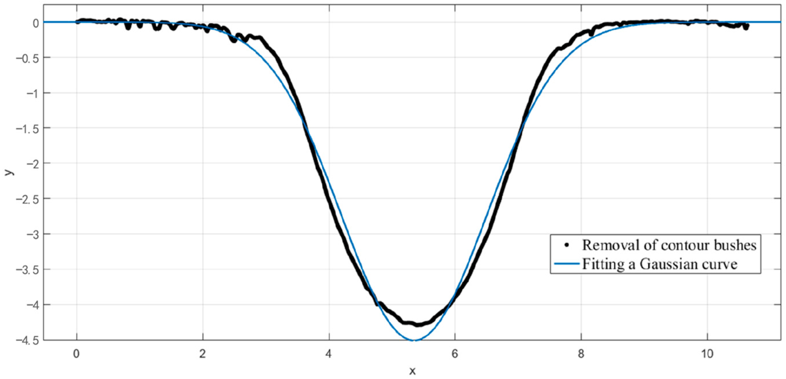
Comparing the measured contour curves of the removal function, it can be found that at a low processing distance, the measured contour curves are very smooth and fit the Gaussian curve, as shown in
Figure 14. When the processing distance is further, some small fluctuations in the contour curves deviate slightly from the Gaussian curve, as shown in
Figure 15. This phenomenon could be attributed to the susceptibility of the plasma jet to the surrounding airflow as the machining distance increases. The influence of the airflow can result in instability in the shape of the plasma jet and cause slight variations in the contour curve.
4.6. Experimental Exploration of Optimal Processing Parameters
To improve the processing rate of SiC wafers via atmospheric plasma polishing, it is necessary to determine the optimal processing parameters. Due to the multitude of process parameters that influence plasma processing efficiency and the intricate interrelationships among these factors, conducting preliminary single-factor experiments only examines the impact of a single process parameter. Consequently, this approach entails certain limitations. It fails to account for the complex coupling effects that may arise from the interactions between multiple process parameters, leading to an incomplete understanding of the overall system behavior. To study the influence of multiple factors on processing and to investigate the optimal processing parameters for processing SiC wafers, orthogonal experiments were designed and conducted based on previous experimental findings.
The factors that affect the plasma removal function and volume removal rate are the Ar, CF
4, and O
2 flow rates, processing power, and processing distance. Four levels of these five factors were taken separately for experimental analysis, and the L
16(4
5) orthogonal experimental table was selected for the design. A total of 16 sets of experiments were conducted, as shown in
Table 6. The same PG1830 roughness profiler was used to detect the removal profile of the machined hole, calculate the
FWHM and peak removal rate, and derive the volume removal rate of the plasma for this parameter.
The volume removal rate is a more intuitive representation of the magnitude of the material removal rate of the plasma from the SiC wafer and is the most critical index for evaluating plasma processing. Therefore, orthogonal experiments were mainly performed on the volume removal rate results for the extreme difference analysis, and K
1, K
2, K
3, K
4, k
1, k
2, k
3, k
4 and the extreme value R corresponding to each factor were calculated, collated, and analyzed, as shown in
Table 7.
Comparing the five extreme differences in R under the volume removal rate index, it can be found that the main order of influence of each process parameter on the volume removal rate of silicon carbide processed by plasma was processing power (4.117), Ar flow rate (4.05), O2 flow rate (3.719), processing distance (3.351), and CF4 flow rate (2.337). The optimal process parameters to improve the machining efficiency were a power of 550 W, a machining distance of 3.5 mm, an Ar flow rate of 15 SLM, a CF4 flow rate of 70 SCCM, and an O2 flow rate of 20 SCCM, with the highest volume removal rate for this process parameter. This combination did not occur in the 16 machining experiments, which also reflects the advantages of orthogonal experiments.
The plasma jet excited with this processing parameter processed the silicon carbide wafer with the processing spot profile curve shown in
Figure 16. The measurement shows that the peak removal rate of the plasma removal function at this parameter is 0.5736 μm, and the half-height width is 3.456 μm. The volume removal rate is calculated to be 9.119 μm
3/s. The comparison shows that the volume removal rate of the removal function at this parameter is the largest and is the optimal processing parameter.


