
A High-Functional-Density Integrated Inertial Switch for Super-Quick Initiation and Reliable Self-Destruction of a Small-Caliber Projectile Fuze

 , ,
, ,
Abstract
:1. Introduction
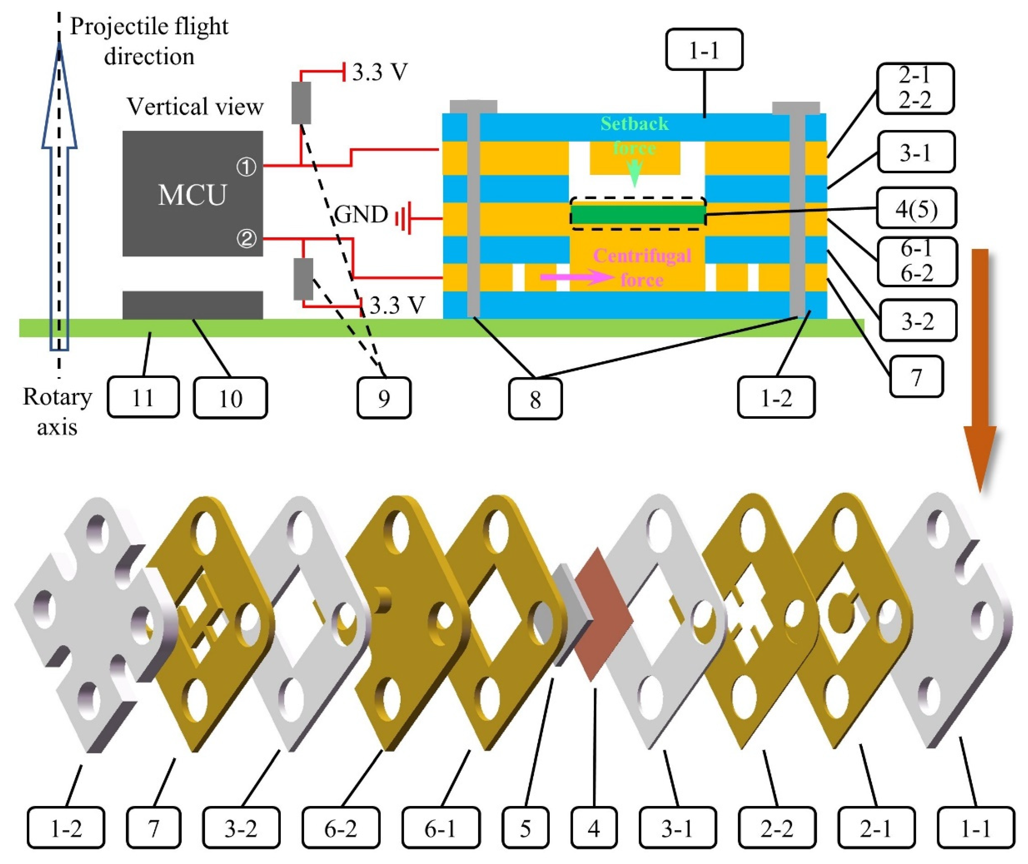
2. Design and Principle: The HFDI Inertial Switch
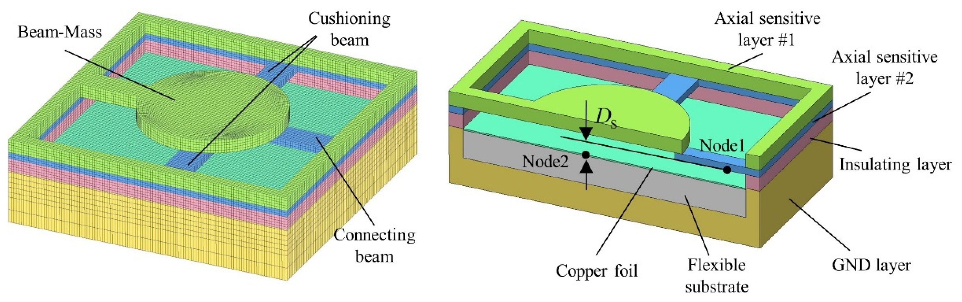
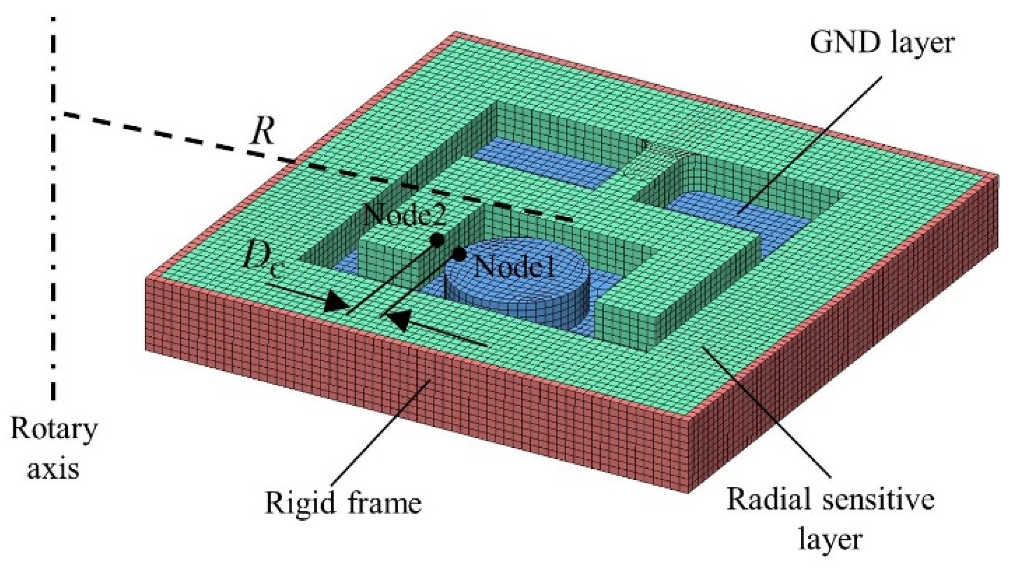
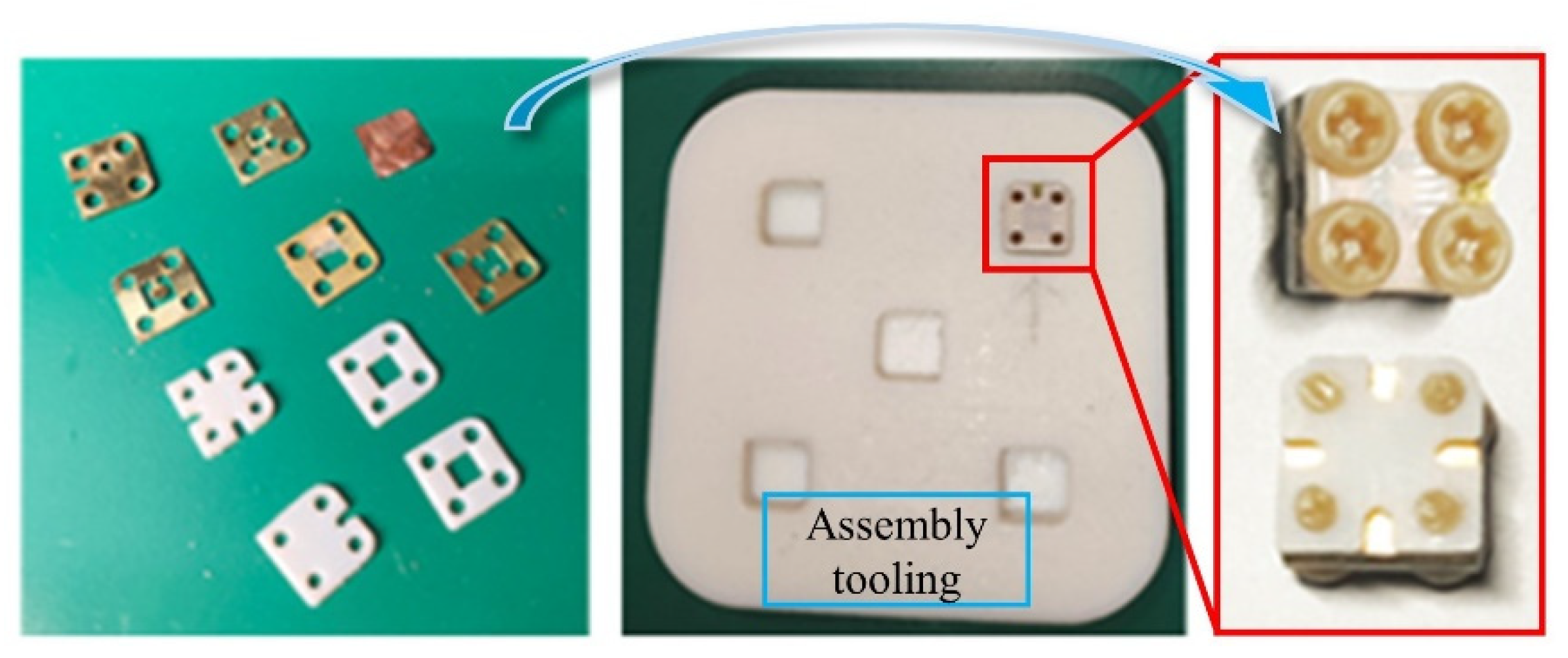
2.1. Structural Design
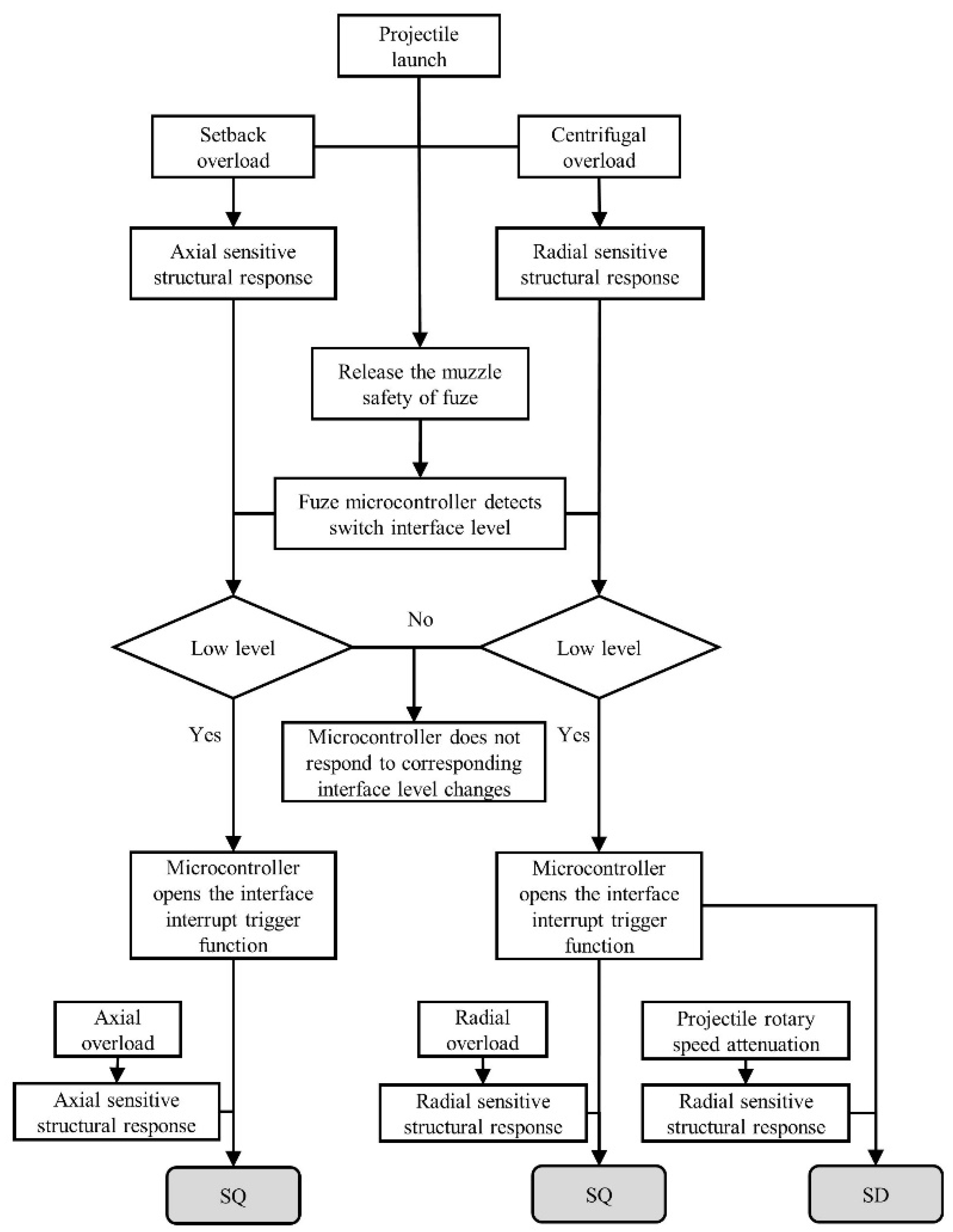
2.2. Working Logic
- (i).
- When the fuze hits the target at a small incident angle, the axial component of the impact overload is large. The switch achieves the “ON-OFF” state transition through the axially sensitive structural response.
- (ii).
- When the fuze hits the target at a large incident angle, the radial component of the impact overload is large, and the switch achieves the “ON-OFF” state transition through the radially sensitive structure’s response. However, it should be noted that owing to the rotation of the projectile, the direction of radial overload when the fuze hits the target is unpredictable. When the direction of overload is similar to the direction of centrifugal force on the radially sensitive structure, the switch cannot reliably complete the state transition.
- (iii).
- When the fuze misses the target and flies for a longer distance, there is no axial/radial overload. The centrifugal force on the radially sensitive structure decreases with the attenuation in projectile rotary speed and is insufficient to resist the restoring force of material elastic deformation. The switch achieves the “ON-OFF” state transition through elastic recovery of the axially sensitive structure.
2.3. Theoretical Analysis
3. Dynamic Simulations of the Whole Ballistic System
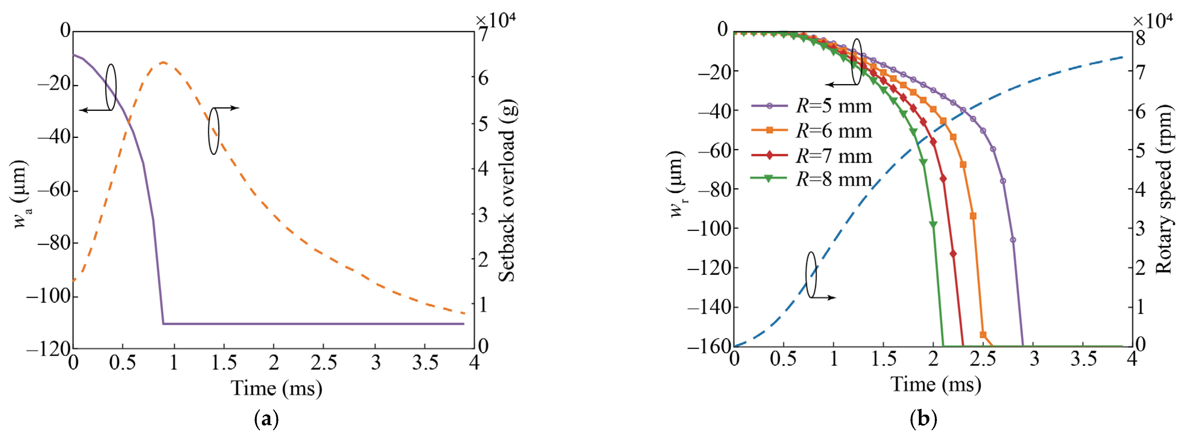
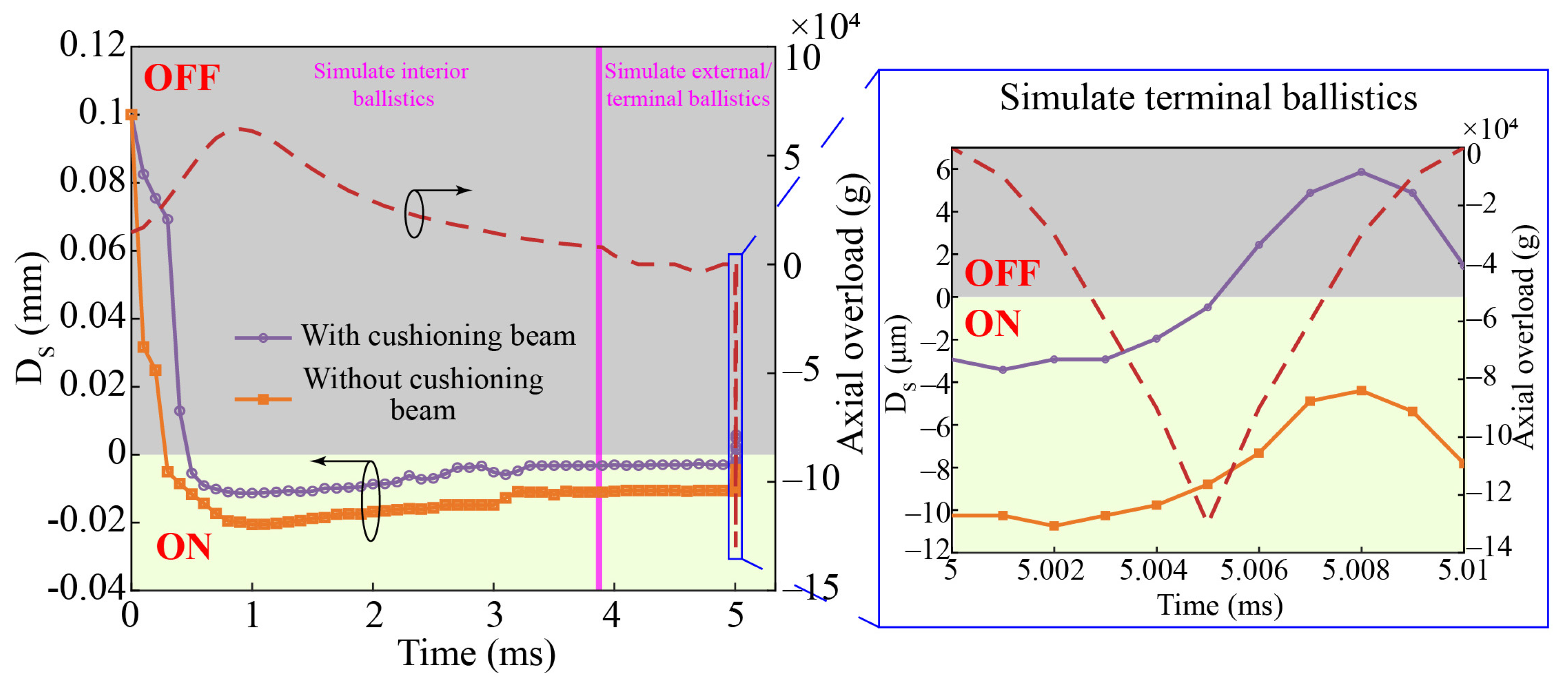
3.1. Dynamic Simulations of Axial Overload
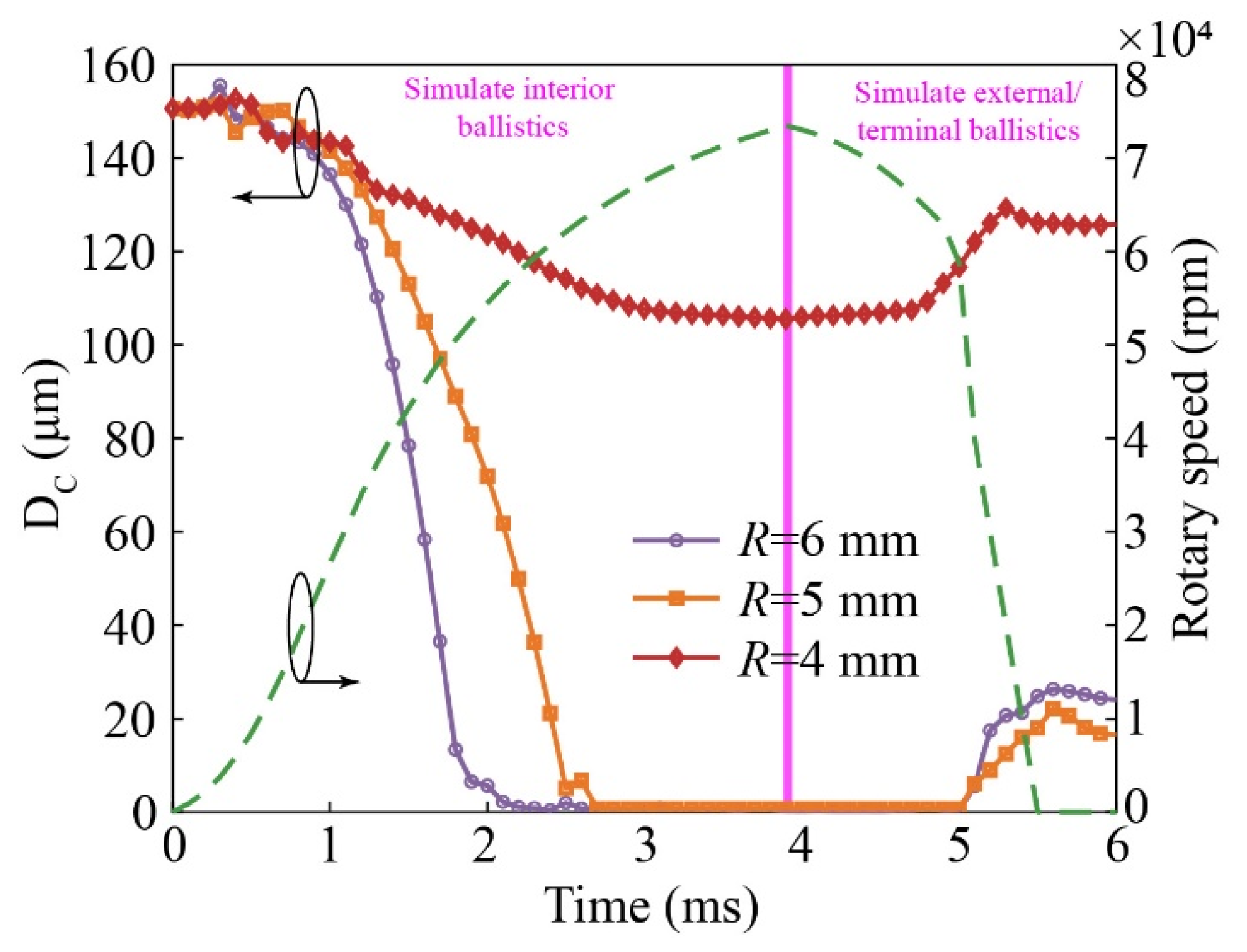
3.2. Dynamic Simulations of Radial Overload
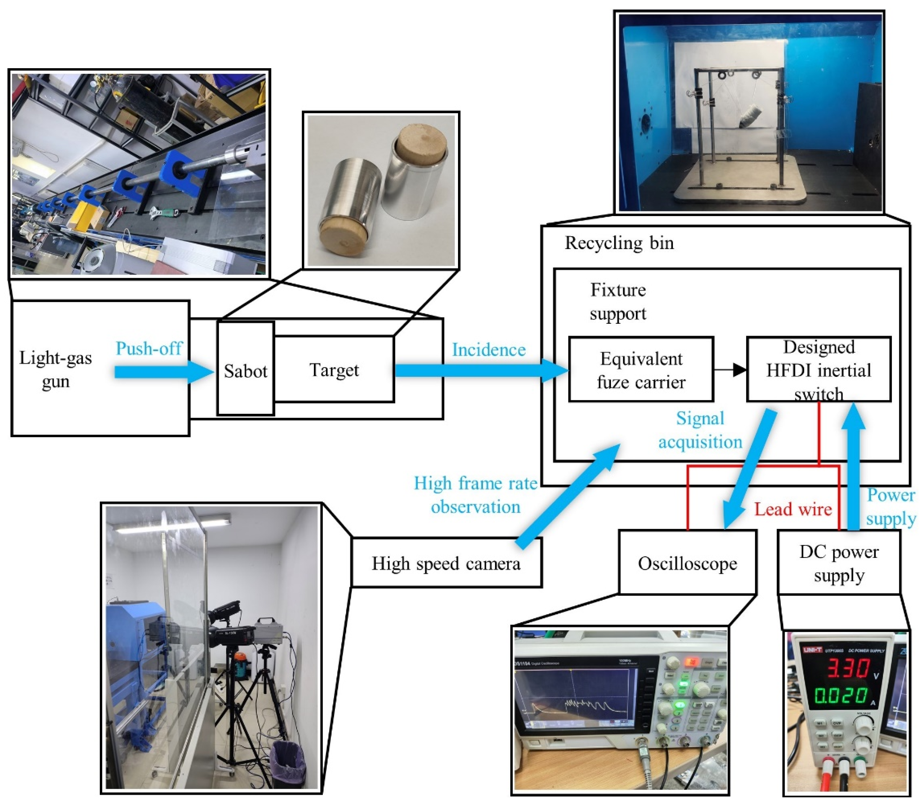
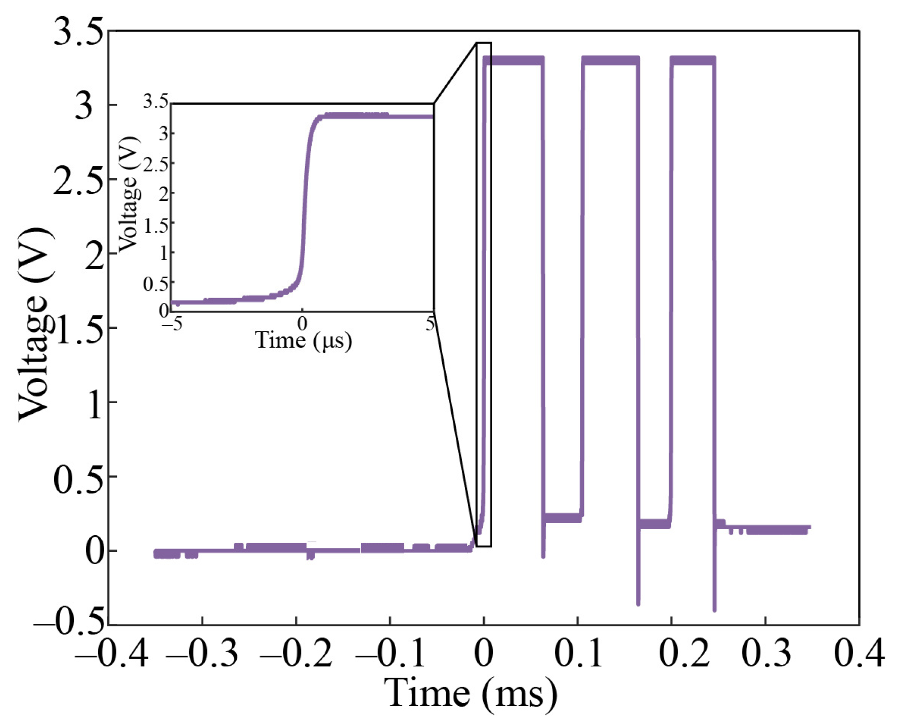
4. Highly Dynamic Testing
5. Conclusions
Author Contributions
Funding
Data Availability Statement
Conflicts of Interest
References
- Lou, W.; He, B.; Qin, J.; Yang, T.; Feng, H.; Lv, S.; Su, W.; Zhang, M. Study on response characteristics of firing mechanism of active small caliber projectile fuze hitting target at large incident angle. Trans. Beijing Inst. Technol. 2023, 43, 118–125. [Google Scholar] [CrossRef]
- Ma, B. Academic Works of Professor Ma Baohua; National Defense Industry Press: Beijing, China, 2003. [Google Scholar]
- Dave, F. Impact switch study modeling and implications. In Proceedings of the NDIA 54th Annual Fuze Conference, Kansas City, MO, USA, 11–13 May 2010. [Google Scholar]
- Walter, M. MEMS retard and impact sensors. In Proceedings of the NDIA 54th Annual Fuze Conference, Kansas City, MO, USA, 11–13 May 2010. [Google Scholar]
- Sam, R.; Danny, C.; Hopper, C.; Todd, C. Low g MEMS inertia switches for fuzing applications. In Proceedings of the NDIA 61th Annual Fuze Conference, San Diego, CA, USA, 15–17 May 2018. [Google Scholar]
- Kevin, M.; O’connor, J. Development in metal MEMS latching setback sensing mechanism. In Proceedings of the NDIA 63th Annual Fuze Conference, Virtual, 4–5 August 2020. [Google Scholar]
- Du, L.; Yu, Y.; Yuan, B.; Guo, C.; Wang, C. A low-g omnidirectional MEMS inertial switch with load direction identification. Microelectron. Eng. 2022, 253, 111679. [Google Scholar] [CrossRef]
- Niyazi, A.; Xu, Q.; Khan, F.; Younis, M. Design, modeling, and testing of a bidirectional multi-threshold MEMS inertial switch. Sens. Actuator A-Phys. 2022, 334, 113219. [Google Scholar] [CrossRef]
- Zhang, P.; Li, Y.; Ren, C.; Zhang, H.; Shi, X.; Liu, Y. A MEMS inertial switch with large scale bi-directional adjustable threshold function. J. Microelectromech. Syst. 2022, 31, 124–133. [Google Scholar] [CrossRef]
- Chen, W.; Wang, R.; Wang, H.; Yang, Z. Design, simulation, and fabrication of a new three-axis inertial switch with a triangular movable electrode structure. Micromachines 2023, 14, 94. [Google Scholar] [CrossRef] [PubMed]
- Xu, Q.; Wang, L.; Younis, M. Multi-threshold inertial switch with acceleration direction detection capability. IRE Trans. Ind. Electron. 2023, 70, 4226–4235. [Google Scholar] [CrossRef]
- Narasimhan, V.; Li, H.; Jianmin, M. Micromachined high-g accelerometers: A review. J. Micromech. Microeng. 2015, 25, 033001. [Google Scholar] [CrossRef]
- Liu, F.; Gao, S.; Niu, S.; Zhang, Y.; Guan, Y.; Gao, C.; Li, P. Optimal design of high-g MEMS piezoresistive accelerometer based on Timoshenko beam theory. Microsyst. Technol. 2018, 24, 855–867. [Google Scholar] [CrossRef]
- Singh, V.; Kumar, V.; Saini, A.; Khosla, P.; Mishra, S. Response analysis of MEMS based high-g acceleration threshold switch under mechanical shock. Int. J. Mech. Mater. Des. 2021, 17, 137–151. [Google Scholar] [CrossRef]
- Ning, X.; Si, X.; Shi, C.; Wang, Z. Cantilever beam based uni-direction high-overload closing inertia switch. Detect. Control 2016, 38, 24–26+32. [Google Scholar]
- Brain, T. Advanced medium caliber HEI ammunition. In Proceedings of the NDIA 37th Annual Guns & Ammunition Symposium & Exhibition, Panama City, FL, USA, 15–18 April 2002. [Google Scholar]
- Chen, J.; Guan, Z.; Yang, C. Comparison of strain ranges and mechanical properties of metal rods under tension and torsion tests. J. Jilin Univ. Eng. Technol. Ed. 2018, 48, 1153–1160. [Google Scholar] [CrossRef]
- Kim, H.; Yeom, K.; Kim, S. Numerical simulation for the front section effect of missile on the target perforation. In Proceedings of the 22nd International Symposium on Ballistics, Vancouver, BC, Canada, 14–18 November 2005. [Google Scholar]
- Hua, J.; Cheng, X.; Shivpuri, R. Process modeling of piercing micro-hole with high pressure water beam. In Proceedings of the 9th International LS-DYNA Conference, Detroit, MI, USA, 4–6 June 2006. [Google Scholar]


| Caliber (mm) | Flight Distance (m) | Speed (m/s) | Rotary Speed (rpm) | Incident Angle (°) | Axial/Radial Overload Peak (g) | Axial/Radial Overload Pulse Width (μs) |
|---|---|---|---|---|---|---|
| 30 | 2000 | 430 | 66,000 | 0 | 180,000/≈0 | 7/≈0 |
| 30 | 140,000/12,000 | 7/>20 | ||||
| 60 | 60,000/24,000 | 8/>20 | ||||
| 90 | 10,000/26,000 | 9/>20 |
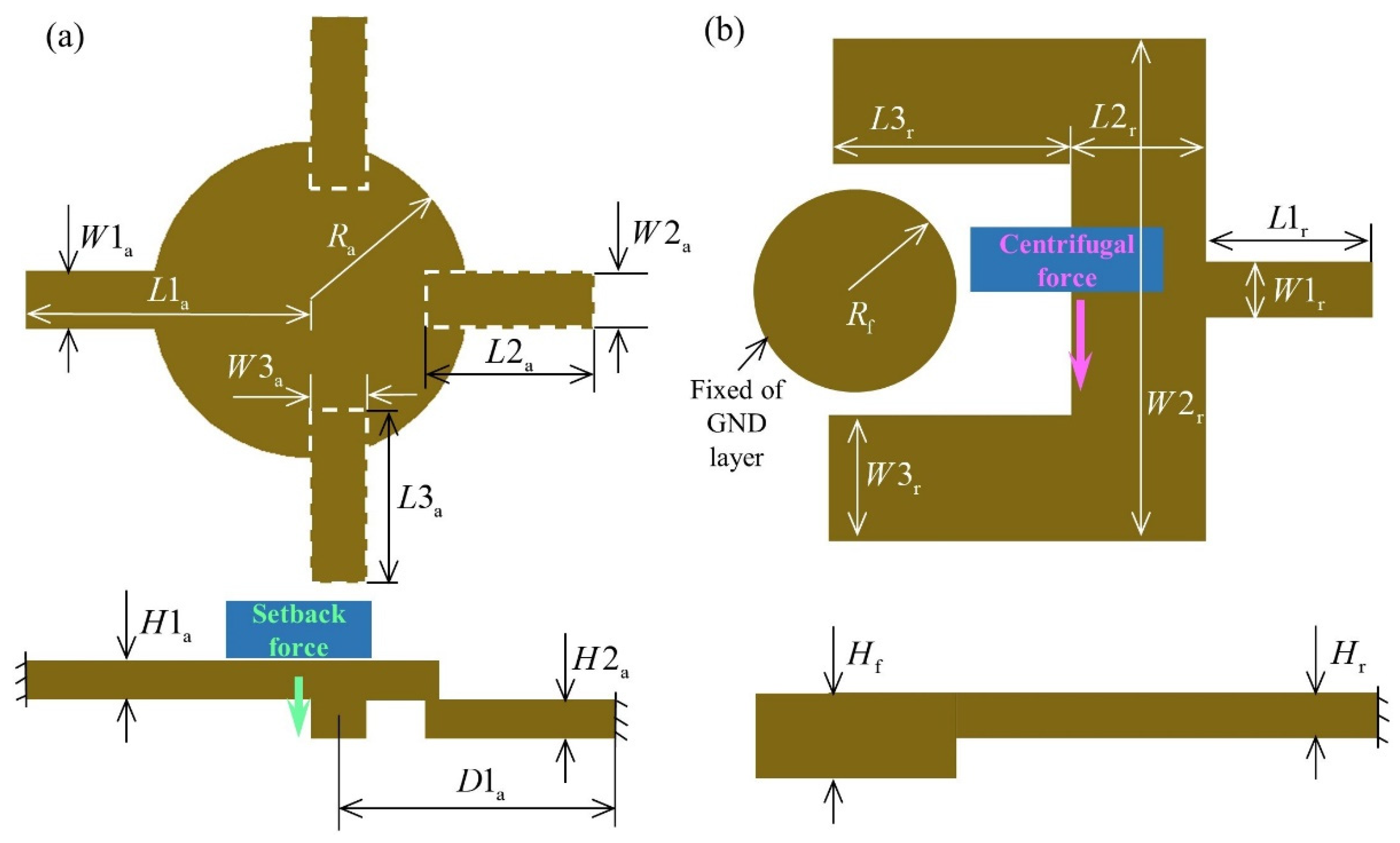
| Components | Geometric Parameters | Value (μm) | Components | Geometric Parameters | Value (μm) |
|---|---|---|---|---|---|
| 1-1: Upper cover plate | 200 | 4: Copper foil | 10 | ||
| 1-2: Bottom cover plate | 200 | 5: Flexible substrate | 200 | ||
| 2-1: Axial sensitive layer #1 | 550 | 6-1: GND layer #1 | 200 | ||
| 200 | 6-2: GND layer #2 | 700 | |||
| 1000 | 400 | ||||
| 100 | 350 | ||||
| 2-2: Axial sensitive layer #2 | 200 | 7: Radial sensitive layer | 200 | ||
| 500 | 600 | ||||
| 200 | 1700 | ||||
| 600 | 400 | ||||
| 900 | 350 | ||||
| 50 | 800 | ||||
| 3-1: Insulating layer #1 | 100 | 200 | |||
| 3-2: Insulating layer #2 | 200 |
| Components | Materials | Constitutive Model | Young’s Modulus (GPa) | Density (kg·m−3) | Poisson’s Ratio | Yield Strength (MPa) |
|---|---|---|---|---|---|---|
| Axial sensitive layer #1 | Brass H62 [17] | MAT_PLASTIC_KINEMATIC | 117.2 | 8912.9 | 0.33 | 239 |
| Axial sensitive layer #1 | ||||||
| GND layer | ||||||
| Insulating layer | Nylon [18] | MAT_PLASTIC_KINEMATIC | 4.5 | 1100.0 | 0.375 | 98 |
| Copper foil | Copper foil [19] | MAT_PLASTIC_KINEMATIC | 115 | 7930.0 | 0.33 | 195 |
| Flexible substrate | PDMS | MAT_PLASTIC_KINEMATIC | 0.003 | 970.0 | 0.49 | – |
| Components | Materials | Constitutive Model | Young’s Modulus (GPa) | Density (kg·m−3) | Poisson’s Ratio | Yield Strength (MPa) |
|---|---|---|---|---|---|---|
| Radial sensitive layer #1 | Brass H62 [17] | MAT_PLASTIC_KINEMATIC | 117.2 | 8912.9 | 0.33 | 239 |
| GND layer |
Disclaimer/Publisher’s Note: The statements, opinions and data contained in all publications are solely those of the individual author(s) and contributor(s) and not of MDPI and/or the editor(s). MDPI and/or the editor(s) disclaim responsibility for any injury to people or property resulting from any ideas, methods, instructions or products referred to in the content. |
© 2023 by the authors. Licensee MDPI, Basel, Switzerland. This article is an open access article distributed under the terms and conditions of the Creative Commons Attribution (CC BY) license (https://creativecommons.org/licenses/by/4.0/).
Share and Cite
He, B.; Yuan, Y.; Ren, J.; Lou, W.; Feng, H.; Zhang, M.; Lv, S.; Su, W. A High-Functional-Density Integrated Inertial Switch for Super-Quick Initiation and Reliable Self-Destruction of a Small-Caliber Projectile Fuze. Micromachines 2023, 14, 1377. https://doi.org/10.3390/mi14071377
He B, Yuan Y, Ren J, Lou W, Feng H, Zhang M, Lv S, Su W. A High-Functional-Density Integrated Inertial Switch for Super-Quick Initiation and Reliable Self-Destruction of a Small-Caliber Projectile Fuze. Micromachines. 2023; 14(7):1377. https://doi.org/10.3390/mi14071377
Chicago/Turabian StyleHe, Bo, Yong Yuan, Jie Ren, Wenzhong Lou, Hengzhen Feng, Mingrong Zhang, Sining Lv, and Wenting Su. 2023. "A High-Functional-Density Integrated Inertial Switch for Super-Quick Initiation and Reliable Self-Destruction of a Small-Caliber Projectile Fuze" Micromachines 14, no. 7: 1377. https://doi.org/10.3390/mi14071377
APA StyleHe, B., Yuan, Y., Ren, J., Lou, W., Feng, H., Zhang, M., Lv, S., & Su, W. (2023). A High-Functional-Density Integrated Inertial Switch for Super-Quick Initiation and Reliable Self-Destruction of a Small-Caliber Projectile Fuze. Micromachines, 14(7), 1377. https://doi.org/10.3390/mi14071377