
Performance Analysis and Experimental Research of a Dual-Vibrator Traveling Wave Ultrasonic Motor

Abstract
:1. Introduction
2. Working Principle
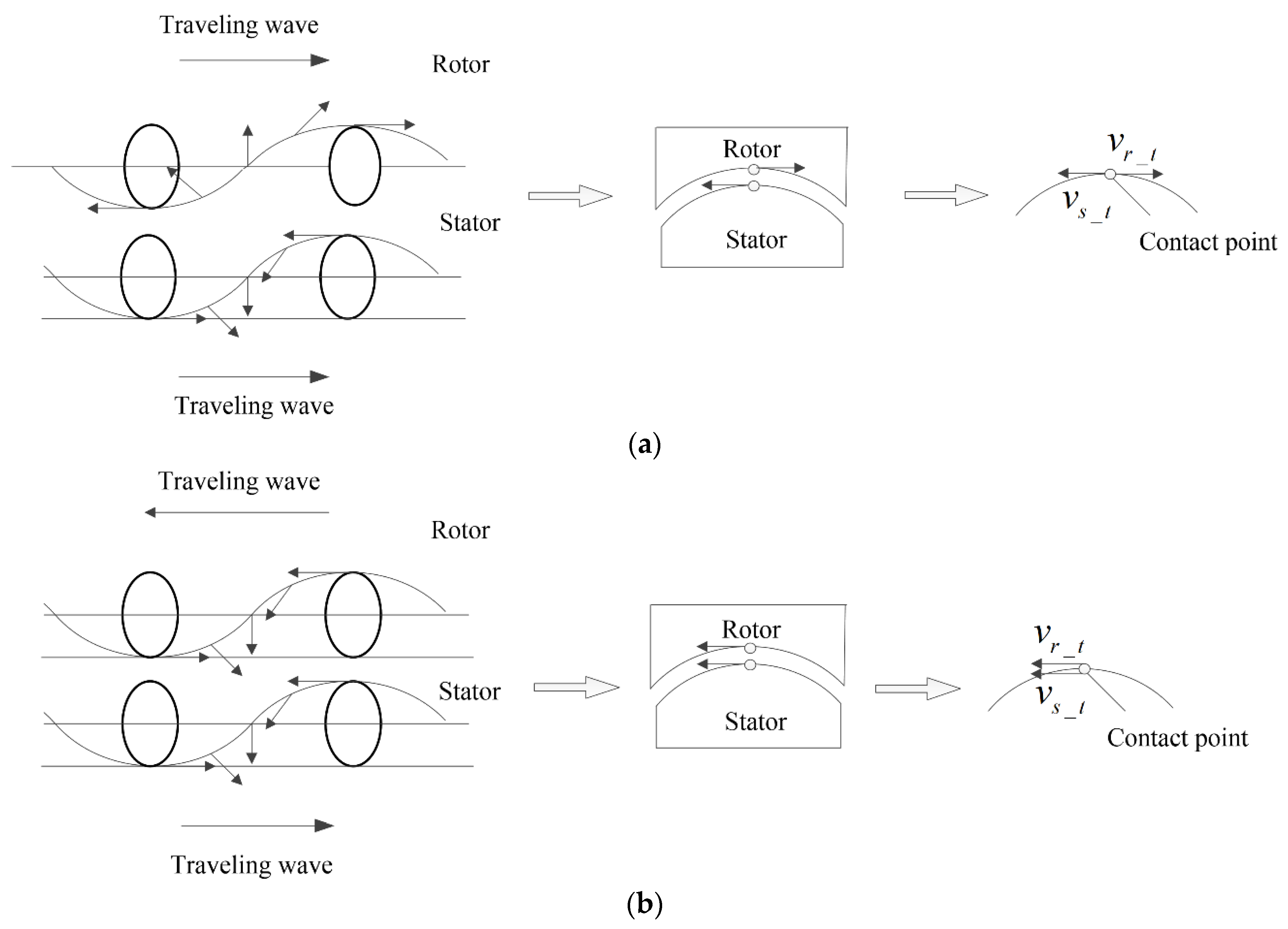
2.1. Velocity Model
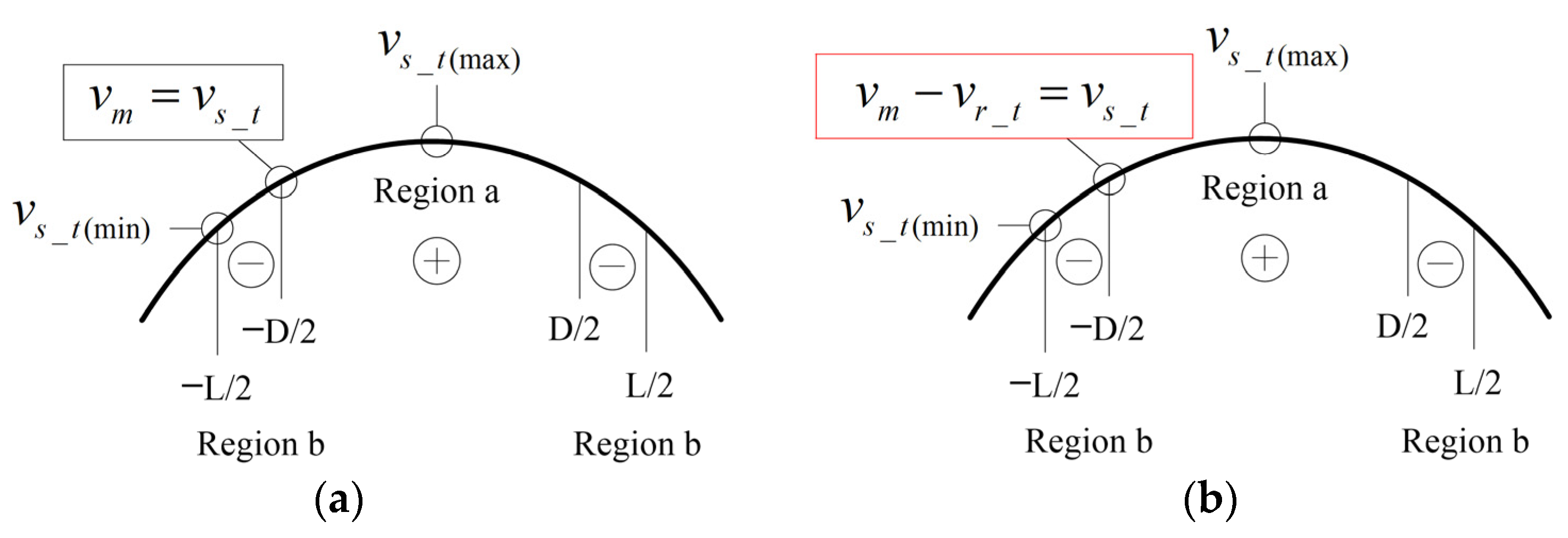
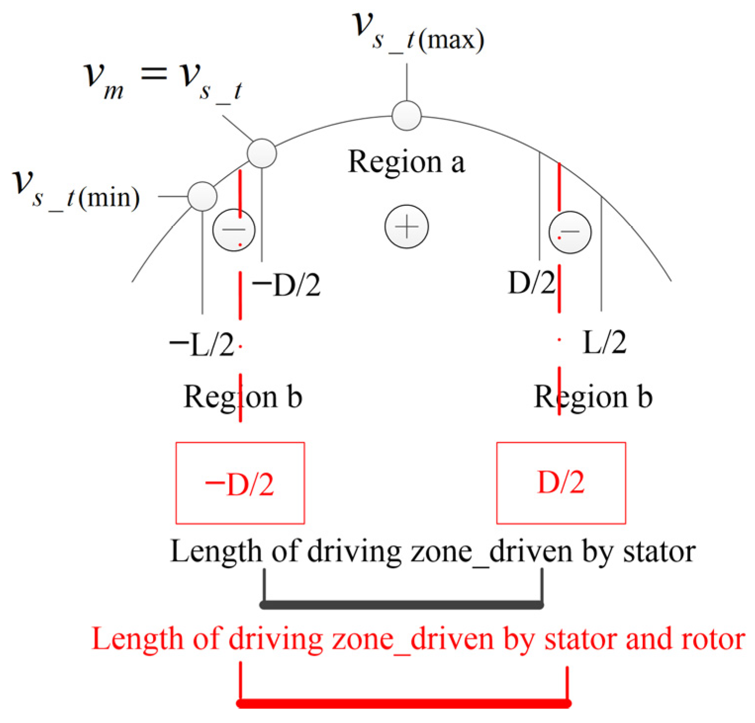
2.2. Contact Model
2.3. Advantages in Performance
- (1)
- Speed advantage
- (2)
- Torque advantage
3. Experiment Analysis
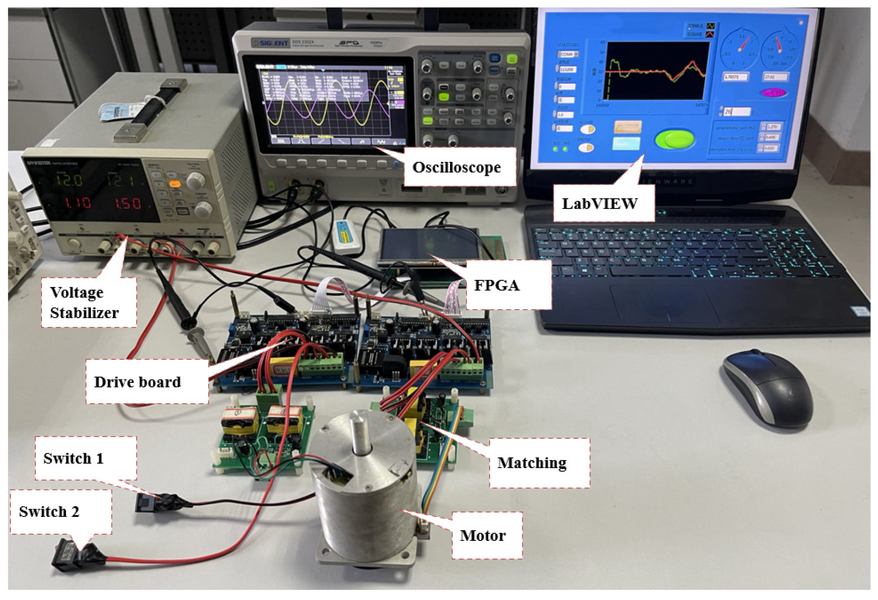
3.1. Motor Drive Strategy
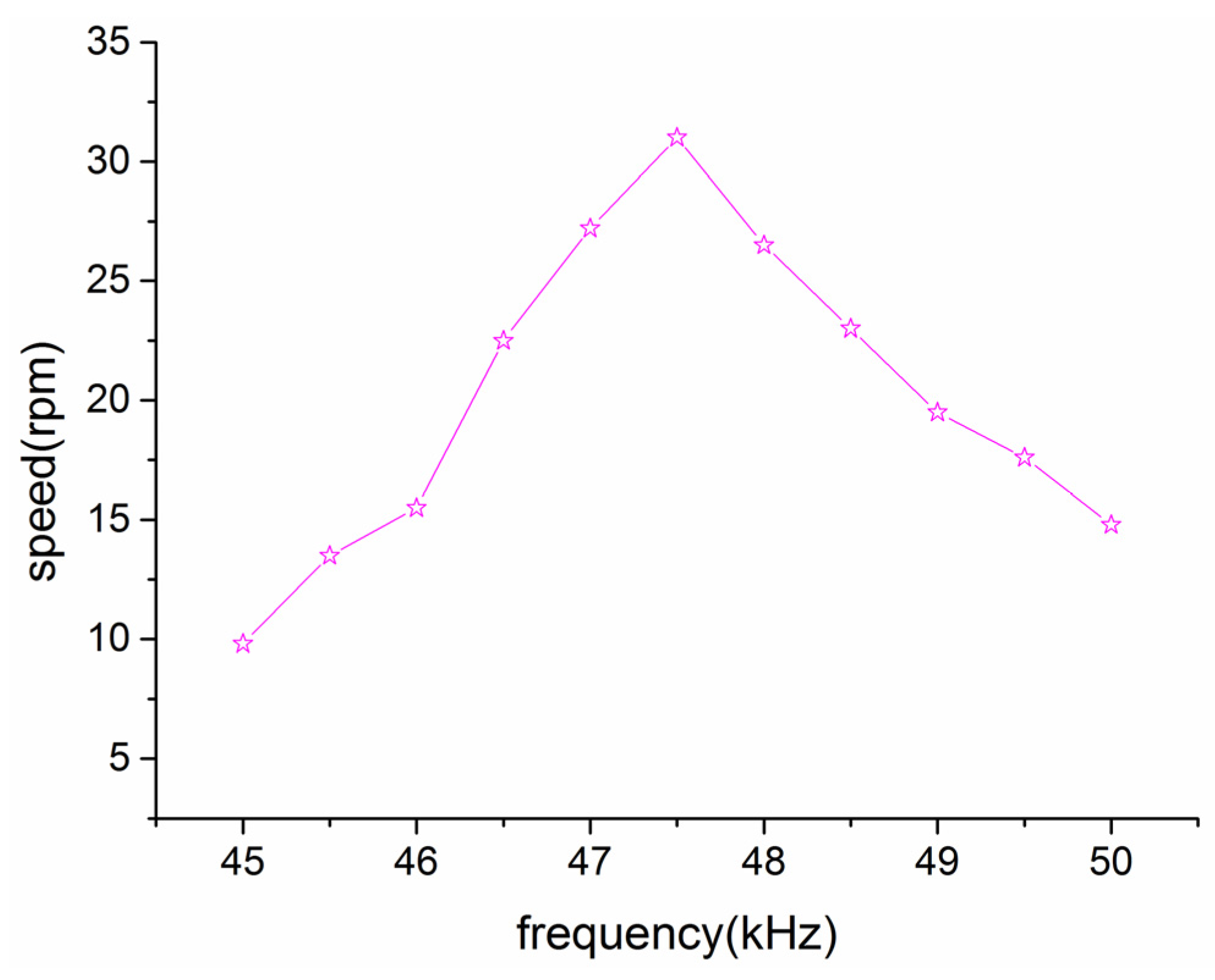
3.2. Motor Performance Test
- (1)
- Single-driven experiment (using the stator)
- (2)
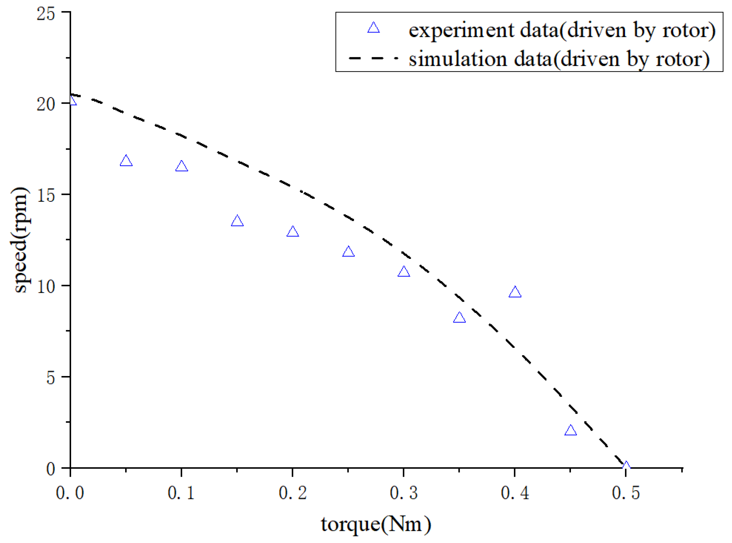
- Single-driven experiment (by rotor)
- (3)
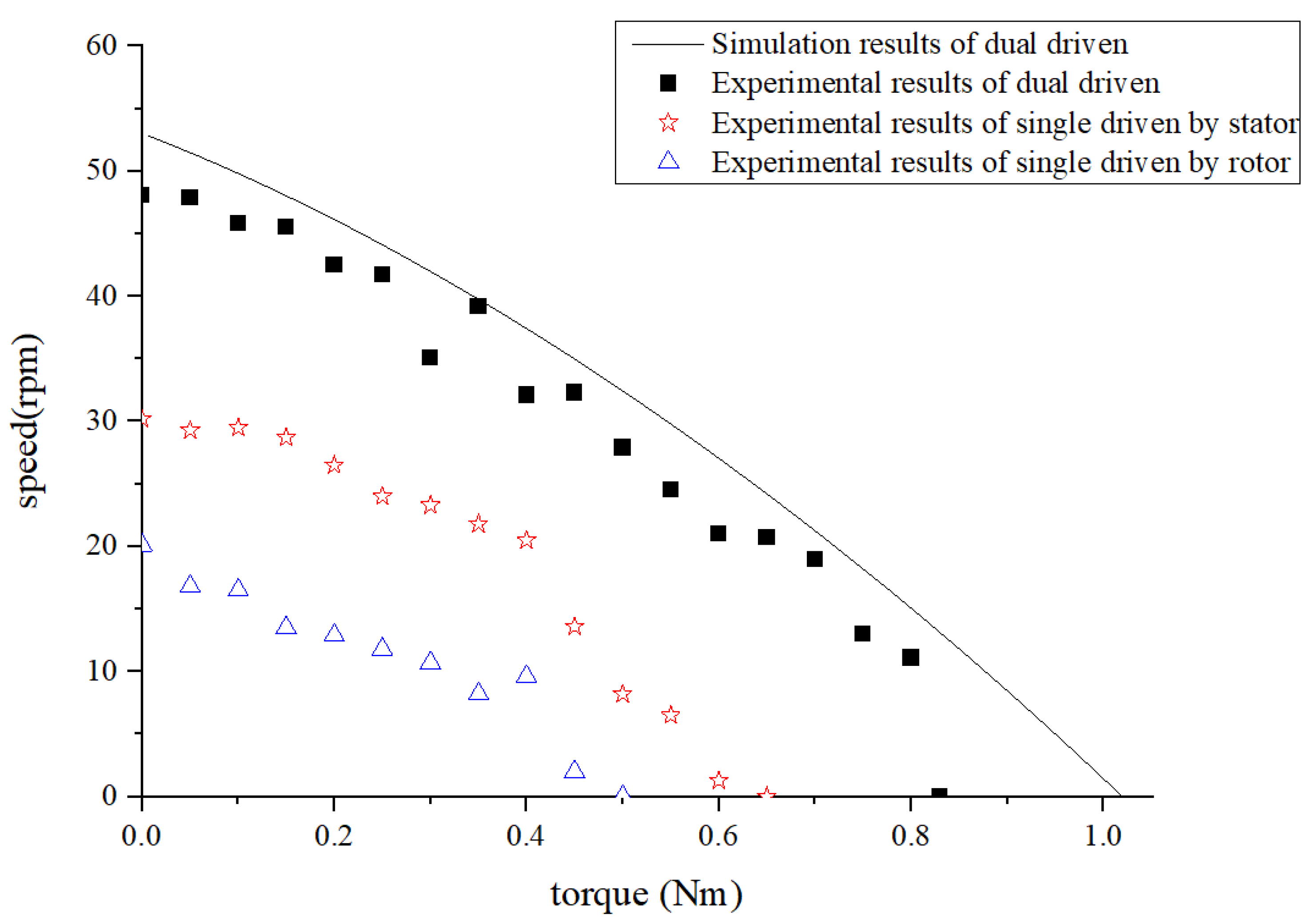
- Dual-driven experiment
4. Conclusions
- (1)
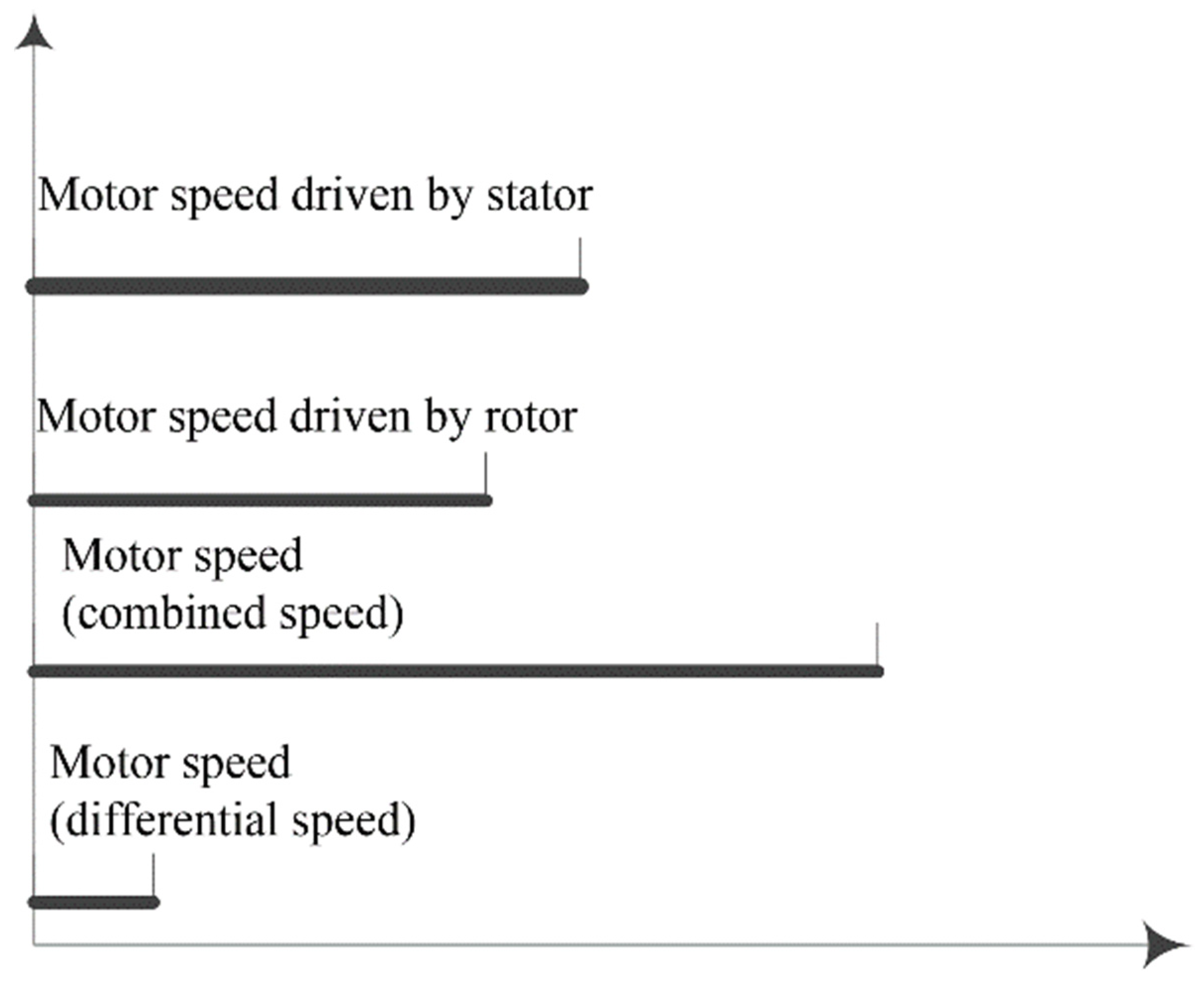
- The dual-vibrator ultrasonic motor features two operational modes: single-driven and dual-driven. In the former, either the stator or the rotor can be driven independently to generate power or motion, respectively; in the latter, both components are simultaneously activated to produce two traveling waves propagating in either parallel or antiparallel directions. The proposed motor demonstrates diverse output performances in response to different driving conditions, as necessitated.
- (2)
- In the dual-driven working mode, when the two traveling waves are in “resultant” motion, the motor’s performance can achieve approximately 90% of the combined output of the single-driven mode by stator and the single-driven mode by rotor; whereas, when the two traveling waves are in “differential” motion, a more pronounced differential effect is observed.
- (3)
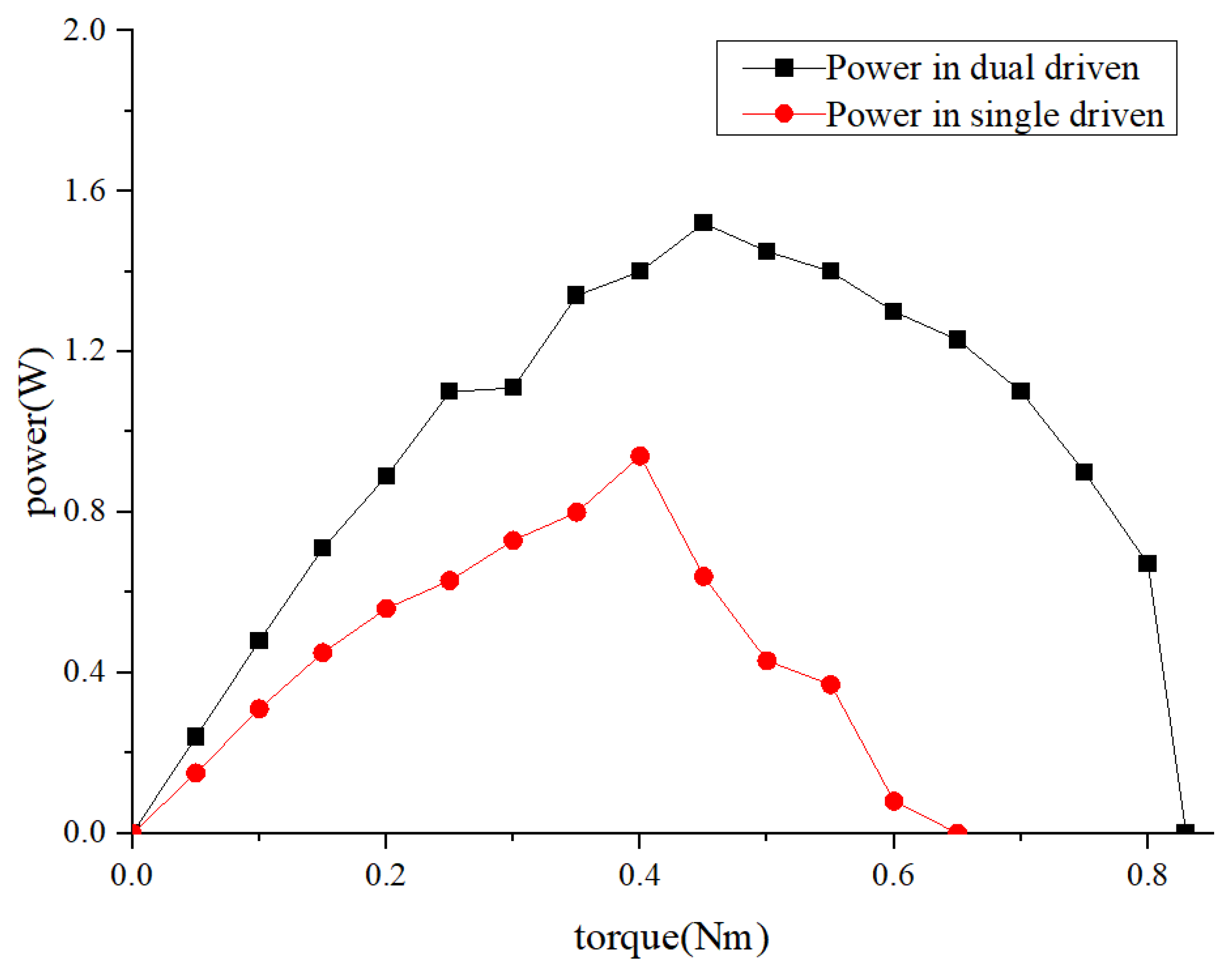
- The maximum speed, torque, and power of the dual-driven mode motor are, respectively, 1.59, 1.28, and 1.62 times that of the single-driven mode by stator.
- (1)
- Because of concerns regarding the impact of friction materials on the interaction between the two traveling wave modes, no friction layer material was incorporated onto the contact surface of the two vibrators, which adversely affects the motor’s performance.
- (2)
- The efficiency of energy conversion is directly correlated with the quality of the piezoelectric ceramic bonding process. Any imperfection in this process can significantly impact the motor’s performance.
- (3)
- The subsequent improvement of the brush structure should take into account the contact force application mechanism between the stator and rotor, as it is crucial for ensuring the motor’s stable performance.
Author Contributions
Funding
Conflicts of Interest
References
- Ueha, S.; Tomikawa, Y.; Kurosawa, M.; Nakamura, N. Ultrasonic Motors: Theory and Applications; Clarendon Press: Oxford, UK, 1993. [Google Scholar]
- Lee, W.H.; Kang, C.Y.; Paik, D.S.; Ju, B.K.; Yoon, S.J. Butterfly-shaped ultra slim piezoelectric ultrasonic linear motor. Sens. Actuators A Phys. 2011, 168, 127–130. [Google Scholar] [CrossRef]
- Pang, Y.; Yang, M.; Li, S. Rotation angle analyses of plate ultrasonic motor under dual-mode coupling drive. Sens. Actuators A Phys. 2012, 173, 202–209. [Google Scholar] [CrossRef]
- Yu, T.H.; Yang, S.Y.; Lee, C.L.; Yin, C.C. Bi-dimensional finite element method for modal separation of a circular cylindrical WW-USM. Finite Elem. Anal. Des. 2011, 47, 635–642. [Google Scholar] [CrossRef]
- Zhao, C.S. Ultrasonic Motors Technologies and Applications; Science Press: Beijing, China, 2011. [Google Scholar]
- Kunioka, T.; Takeda, Y.; Matsuda, T.; Shimazu, Y.; Nakamuya, Y. XY stage driven by ultrasonic linear motors for the electron-beam x-ray mask writer EB-X3. J. Vac. Sci. Technol. B Microelectron. Nanometer Struct. 1999, 17, 2917–2920. [Google Scholar] [CrossRef]
- Uchino, K. Piezoelectric actuator 2006: Expansion from IT/robotics to ecological/energy applications. J. Electroceram. 2008, 20, 301–311. [Google Scholar] [CrossRef]
- Kurosawa, M.K.; Kodaira, O.; Tsuchitoi, Y.; Higuchi, T. Transducer for high speed and large thrust ultrasonic linear motor using two sandwich-type vibrators. IEEE Trans. Ultrason. Ferroelectr. Freq. Control 1998, 45, 1188–1195. [Google Scholar] [CrossRef] [PubMed]
- Satonobu, J.; Friend, J.R.; Nakamura, K.; Ueha, S. Numerical analysis of the symmetric hybrid transducer ultrasonic motor. IEEE Trans. Ultrason. Ferroelectr. Freq. Control 2001, 48, 1625–1631. [Google Scholar] [PubMed]
- Iula, A.; Pappalardo, M. A high-power traveling wave ultrasonic motor. IEEE Trans. Ultrason. Ferroelectr. Freq. Control 2006, 53, 1344–1351. [Google Scholar] [PubMed]
- Bai, D.; Ishii, T.; Nakamura, K.; Ueha, S.; Yonezawa, T.; Takahashi, T. An ultrasonic motor driven by the phase-velocity difference between two traveling waves. IEEE Trans. Ultrason. Ferroelectr. Freq. Control. 2004, 51, 680–685. [Google Scholar] [PubMed]
- Pang, Y.; Yang, M.; Chen, X.; He, W.; Li, S.; Li, C. Performance Evaluation of Dual-frequency Driving Plate Ultrasonic Motor Based on analytical model. IEEE Trans. Ultrason. Ferroelectr. Freq. Contr. 2011, 58, 1641–1650. [Google Scholar]
- Koc, B.; Von Deyn, L.; Delibas, B. Dual source dual frequency drive and modeling of resonance type piezoelectric motor. In Proceedings of the International Conference and Exhibition on New Actuators and Drive Systems, Online, 17–19 February 2021; pp. 62–65. [Google Scholar]
- Chen, T.-C.; Yu, C.-H.; Tsai, M.-C. A new driver based on dual-mode frequency and phase control for traveling-wave type ultrasonic motor. Energy Convers. Manag. 2008, 49, 2767–2775. [Google Scholar]
- Jiawan, T.; Langtao, Y.; Yusheng, L.; Sanshan, H. Realization of the Ultrasonic Motor Speed Control System Based on H-Bridge. Math. Probl. Eng. 2021, 2021, 8106164. [Google Scholar]


| Nm | Single Driven by Stator (A) | Single Driven by Rotor (B) | Dual Driven | Sum of A and B | Relative Difference | |
|---|---|---|---|---|---|---|
| rpm | ||||||
| 30.2 | 20.1 | 48.1 | 50.3 | 4.37% | ||
| 29.5 | 16.5 | 45.8 | 46 | 0.43% | ||
| 26.5 | 12.9 | 42.5 | 39.4 | 7.87% | ||
| 24.8 | 10.7 | 35.1 | 35.5 | 1.13% | ||
| 22.4 | 9.6 | 32.1 | 32 | 0.31% | ||
| Single Driven by Stator | Dual Driven | Increment | |
|---|---|---|---|
| Maximum speed (rpm) | 30.2 | 48.1 | 59% |
| Maximum torque (Nm) | 0.65 | 0.83 | 28% |
| Nm | Driven by Stator | Driven by Rotor | Dual Driven | Absolute Difference | Lift Amount | |
|---|---|---|---|---|---|---|
| rpm | ||||||
| 30.2 | 19.7 | 10.8 | 10.5 | 2.78% | ||
| 29.5 | 17.5 | 12.5 | 12 | 4% | ||
| 26.5 | 13.9 | 11.8 | 12.6 | 6.78% | ||
| 23.3 | 11.7 | 9.9 | 11.6 | 17.17% | ||
| 18.1 | 9.6 | 6.7 | 8.5 | 21.17% | ||
Disclaimer/Publisher’s Note: The statements, opinions and data contained in all publications are solely those of the individual author(s) and contributor(s) and not of MDPI and/or the editor(s). MDPI and/or the editor(s) disclaim responsibility for any injury to people or property resulting from any ideas, methods, instructions or products referred to in the content. |
© 2023 by the authors. Licensee MDPI, Basel, Switzerland. This article is an open access article distributed under the terms and conditions of the Creative Commons Attribution (CC BY) license (https://creativecommons.org/licenses/by/4.0/).
Share and Cite
Dong, Z.; Xu, L. Performance Analysis and Experimental Research of a Dual-Vibrator Traveling Wave Ultrasonic Motor. Micromachines 2023, 14, 1610. https://doi.org/10.3390/mi14081610
Dong Z, Xu L. Performance Analysis and Experimental Research of a Dual-Vibrator Traveling Wave Ultrasonic Motor. Micromachines. 2023; 14(8):1610. https://doi.org/10.3390/mi14081610
Chicago/Turabian StyleDong, Zhaopeng, and Liang Xu. 2023. "Performance Analysis and Experimental Research of a Dual-Vibrator Traveling Wave Ultrasonic Motor" Micromachines 14, no. 8: 1610. https://doi.org/10.3390/mi14081610