

Ultra-Compact Low-Pass Spoof Surface Plasmon Polariton Filter Based on Interdigital Structure
 ,
,
Abstract
:1. Introduction
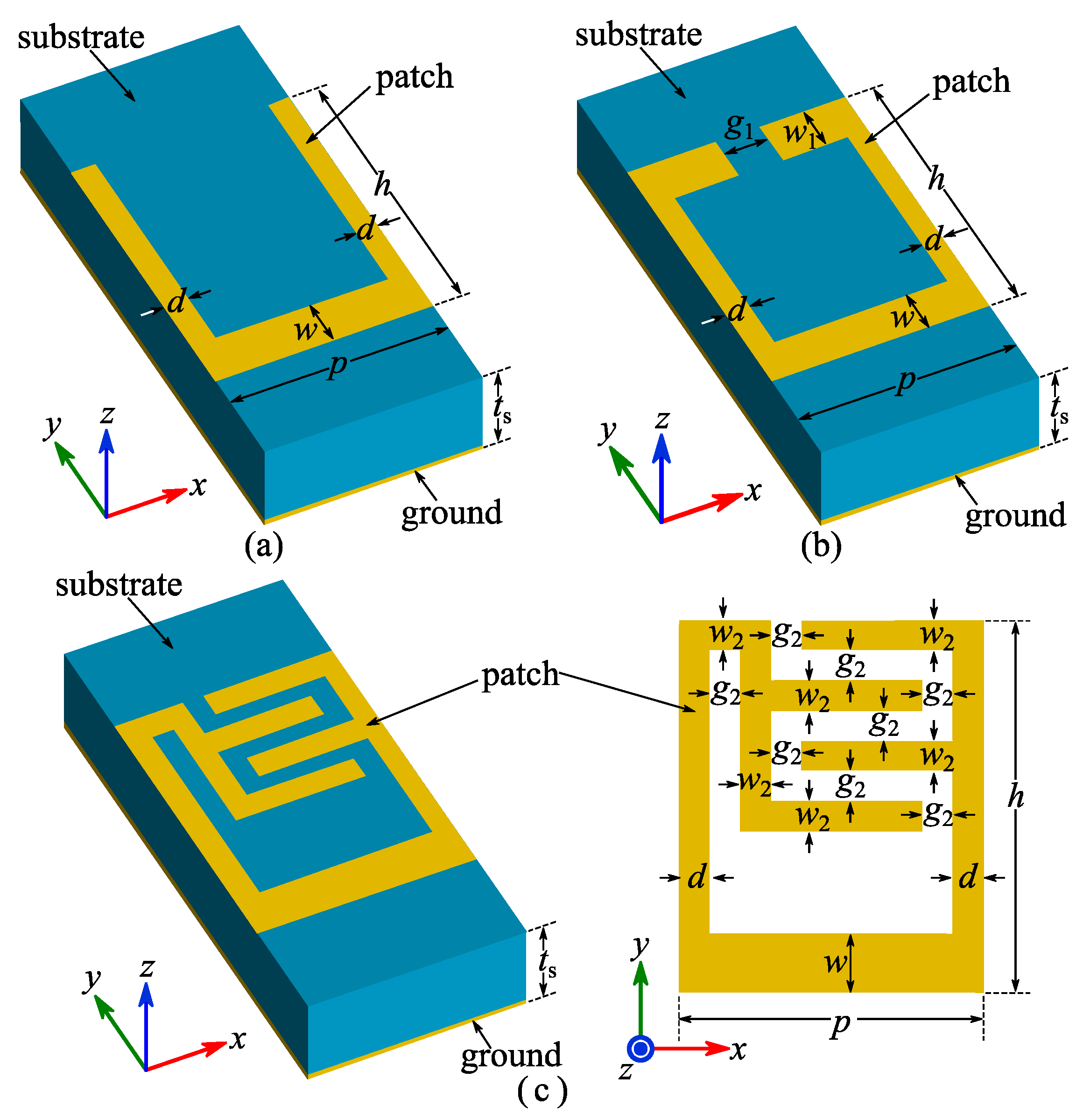
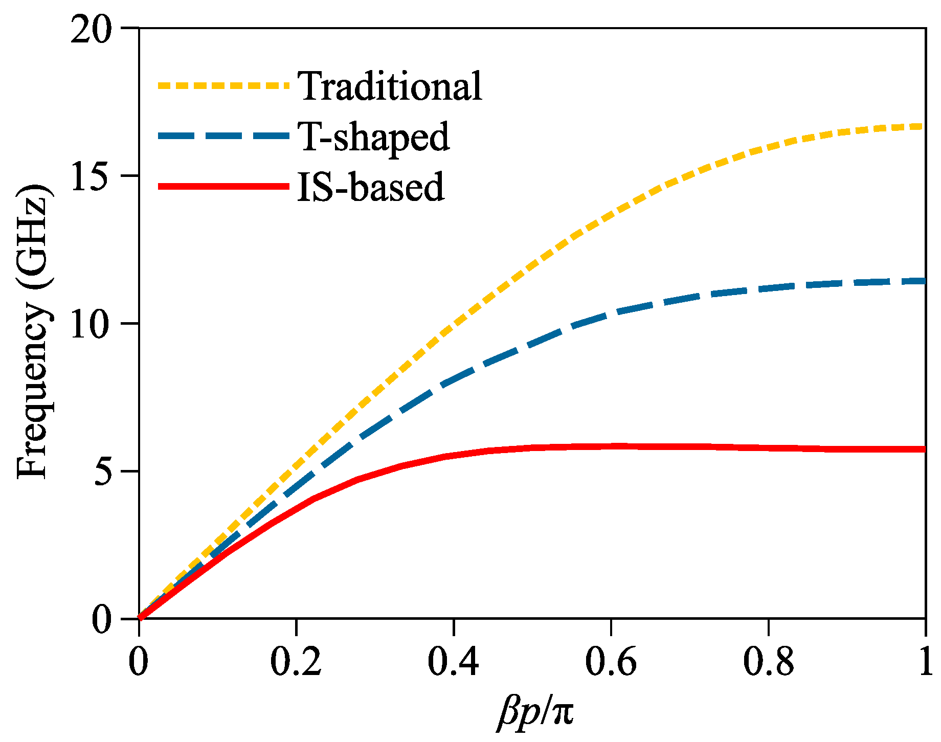
2. Unit Design
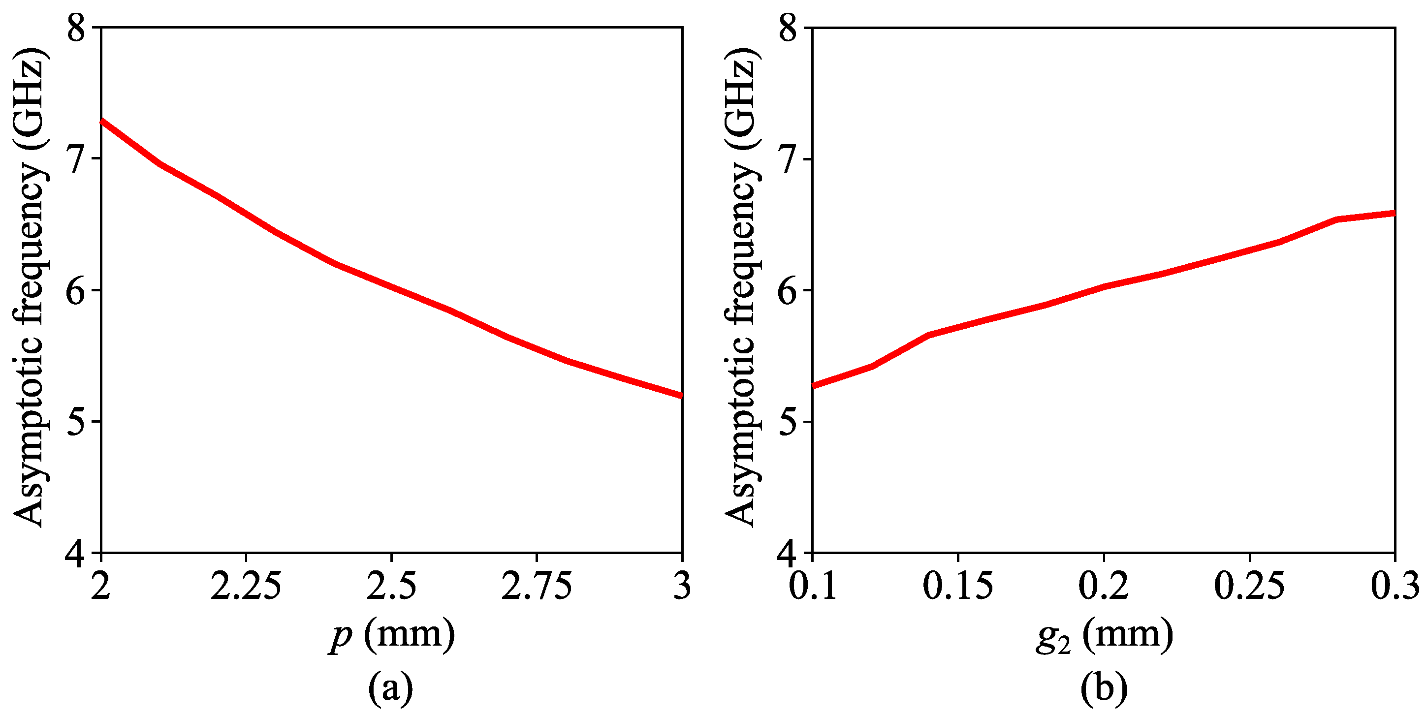
3. Geometry Design of Proposed Filter
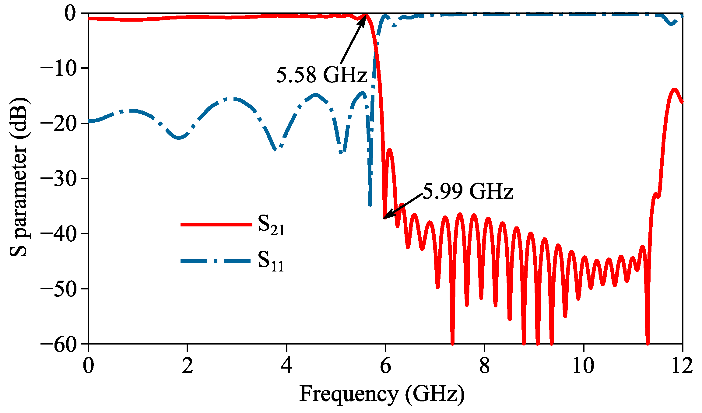
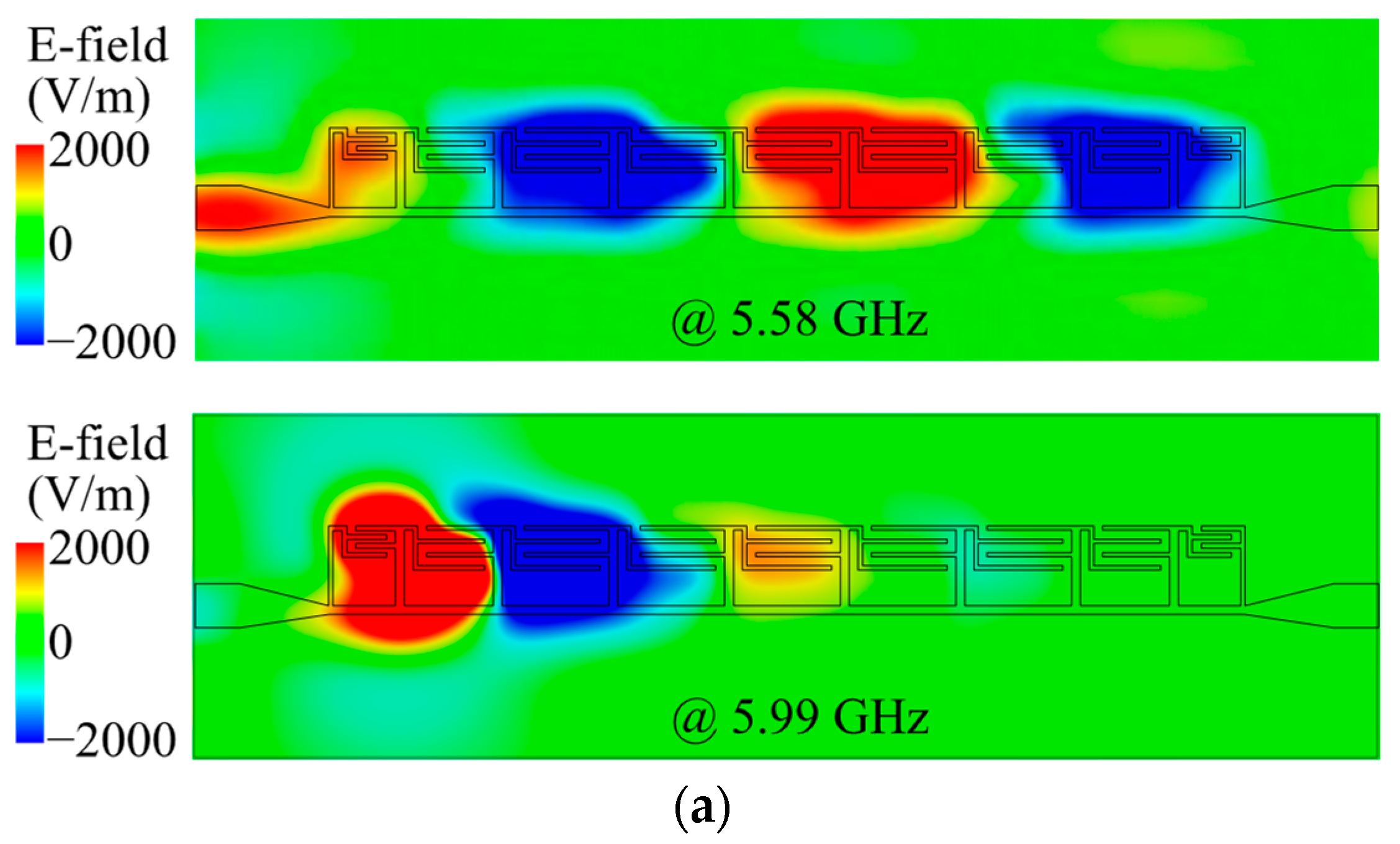
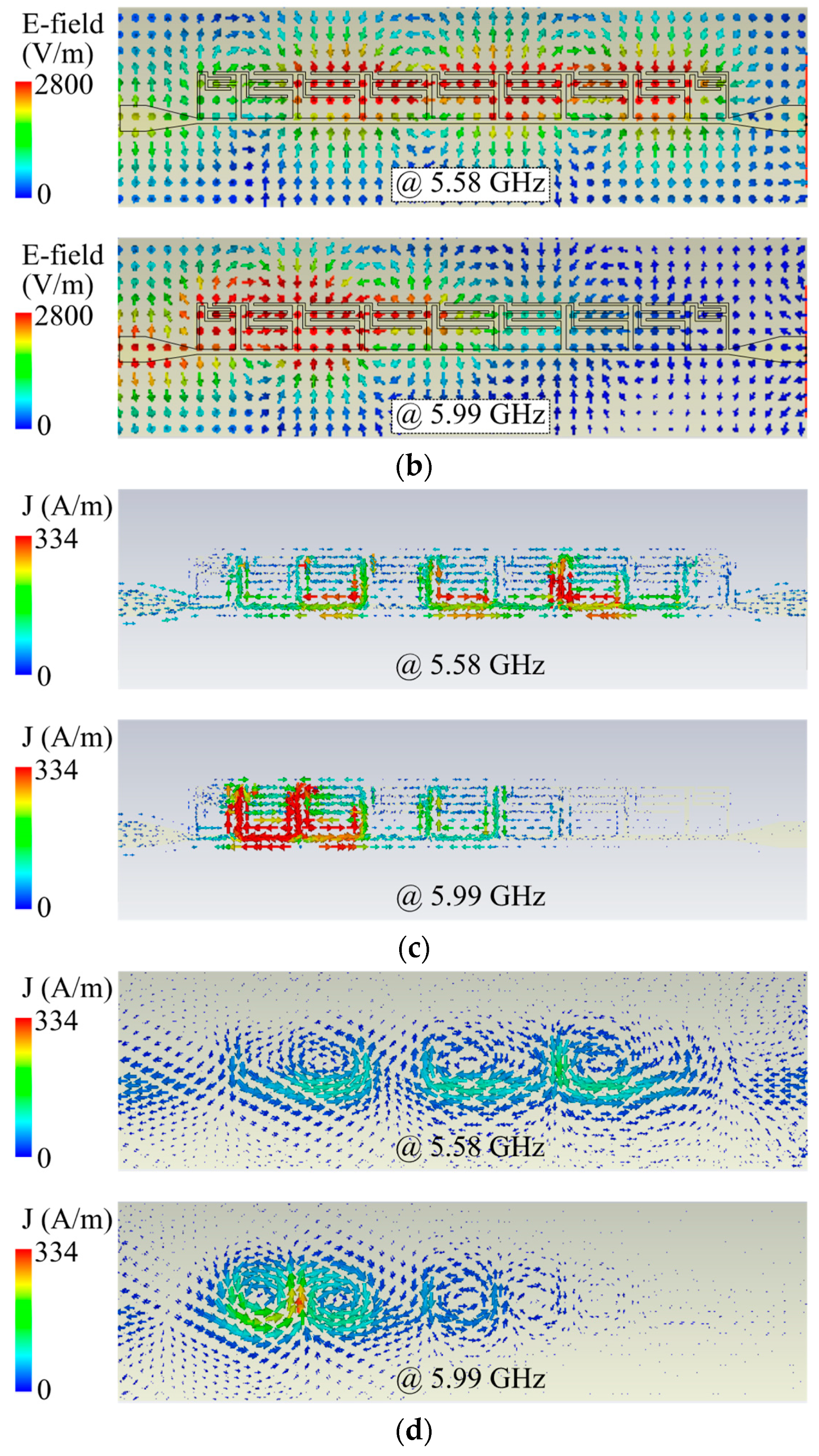
4. Simulation Results of Proposed Filter
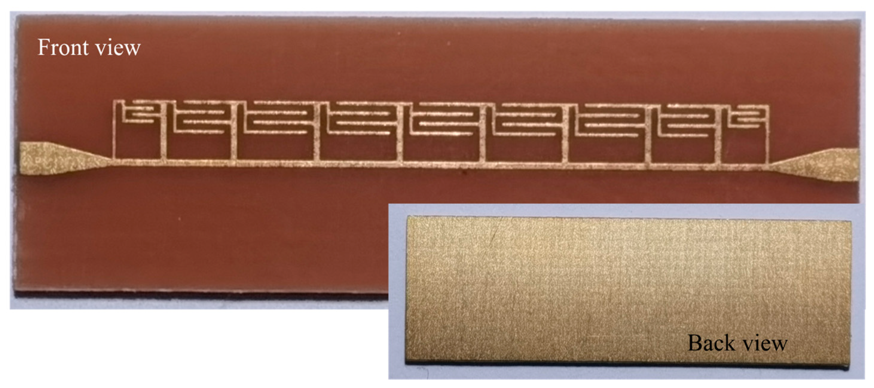
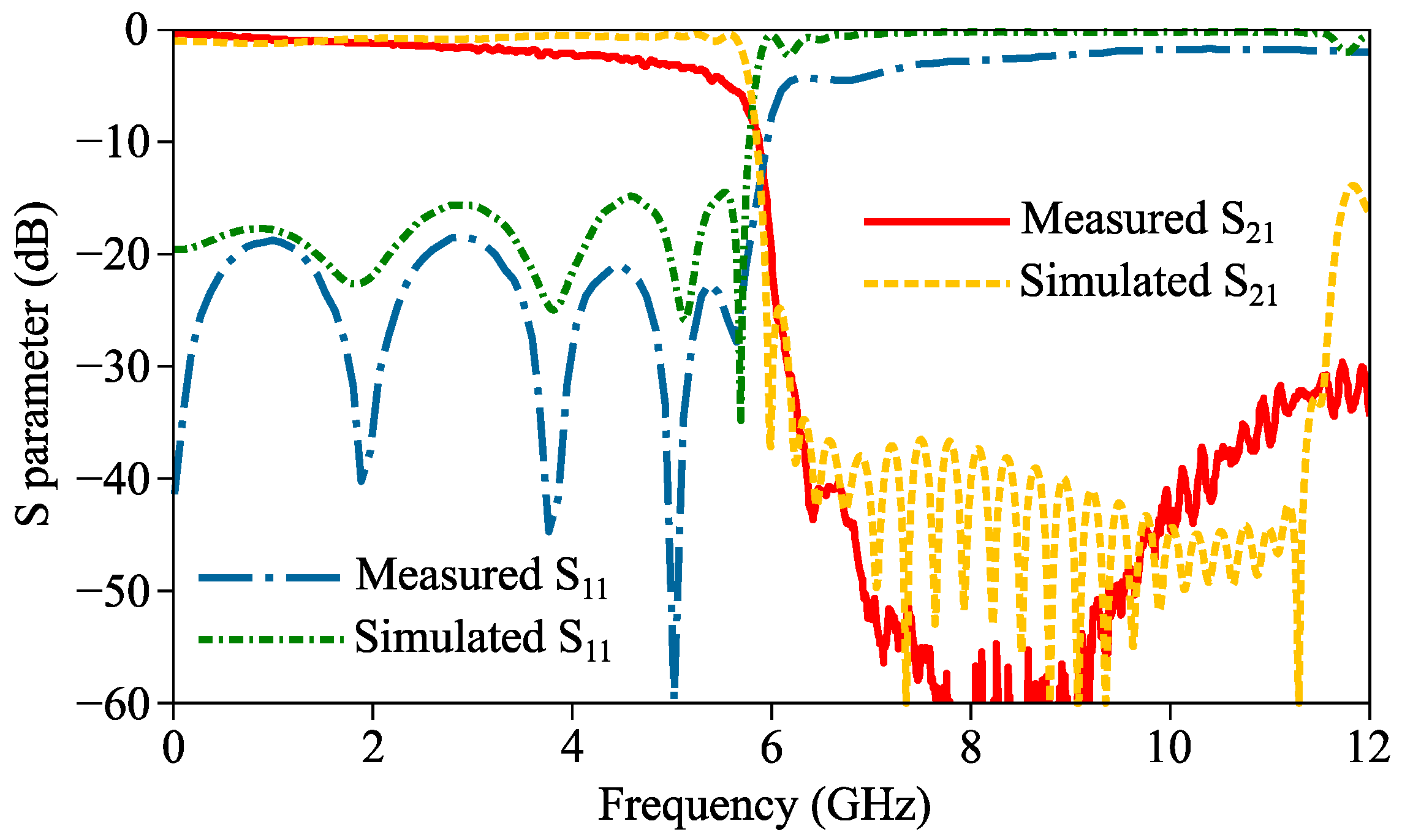
5. Prototype Fabrication and Measurements of Proposed Filter
6. Conclusions
Author Contributions
Funding
Data Availability Statement
Conflicts of Interest
References
- Bardeen, J.; Cooper, L.N.; Schrieffer, J.R. Microscopic theory of superconductivity. Phys. Rev. 1957, 106, 162–164. [Google Scholar] [CrossRef]
- Zayats, A.V.; Smolyaninov, I.I.; Maradudin, A.A. Nano-optics of surface plasmon polaritons. Phys. Rep. 2005, 408, 131–314. [Google Scholar] [CrossRef]
- Gramotnev, D.; Bozhevolnyi, S. Plasmonics beyond the diffraction limit. Nat. Photonics 2010, 4, 83–91. [Google Scholar] [CrossRef]
- Zhang, J.; Zhang, L.; Xu, W. Surface plasmon polaritons: Physics and applications. J. Phys. D Appl. Phys. 2012, 45, 113001. [Google Scholar] [CrossRef]
- Han, Z.; Bozhevolnyi, S.I. Radiation guiding with surface plasmon polaritons. Rep. Prog. Phys. 2012, 76, 016402. [Google Scholar] [CrossRef]
- Hibbins, A.P.; Evans, B.R.; Sambles, J.R. Experimental verification of designer surface plasmons. Science 2005, 308, 670–672. [Google Scholar] [CrossRef]
- Zhang, Y.; Lu, Y.; Yuan, M.; Xu, Y.; Xu, Q.; Yang, Q.; Liu, Y.; Gu, J.; Li, Y.; Tian, Z.; et al. Rotated pillars for functional integrated on-chip terahertz spoof surface-plasmon-polariton devices. Adv. Opt. Mater. 2022, 10, 2102561. [Google Scholar] [CrossRef]
- Su, X.; Dong, L.; Wen, L.; Liu, Y.; Li, Y.; Ouyang, C.; Xu, Q.; Zhang, X.; Shi, Y.; Han, J. Cascaded plasmon-induced transparency in spoof surface plasmon polariton waveguide. Results Phys. 2022, 43, 106044. [Google Scholar] [CrossRef]
- Pendry, J.; Martin-Moreno, L.; Garcia-Vidal, F. Mimicking surface plasmons with structured surfaces. Science 2004, 305, 847–848. [Google Scholar] [CrossRef]
- Maier, S.A.; Andrews, S.R.; Martin-Moreno, L.; Garcia-Vidal, F.J. Terahertz surface plasmon polariton propagation and focusing on periodically corrugated metal wires. Phys. Rev. Lett. 2006, 97, 176805. [Google Scholar] [CrossRef]
- Zhou, Y.J.; Xiao, Q.X. Electronically controlled rejections of spoof surface plasmons polaritons. J. Appl. Phys. 2017, 121, 123109. [Google Scholar] [CrossRef]
- Zhang, H.C.; He, P.H.; Gao, X.; Tang, W.X.; Cui, T.J. Pass-band reconfigurable spoof surface plasmon polaritons. J. Phys. Condens. 2018, 30, 134004. [Google Scholar] [CrossRef] [PubMed]
- Yin, J.Y.; Ren, J.; Zhang, Q.; Zhang, H.C.; Liu, Y.Q.; Li, Y.B.; Wan, X.; Cui, T.J. Frequency-controlled broad-angle beam scanning of patch array fed by spoof surface plasmon polaritons. IEEE Trans. Antennas Propag. 2016, 64, 5181–5189. [Google Scholar] [CrossRef]
- Lu, J.; Zhang, H.C.; He, P.H.; Zhang, L.P.; Cui, T.J. Design of miniaturized antenna using corrugated microstrip. IEEE Trans. Antennas Propag. 2020, 68, 1918–1924. [Google Scholar] [CrossRef]
- Pan, Y.; Cheng, Y.; Dong, Y. Surface plasmon polariton leaky-wave antennas with wideband arbitrary multibeam radiation. IEEE Trans. Antennas Propag. 2022, 70, 931–942. [Google Scholar] [CrossRef]
- Liu, L.; Fu, Q.; Hu, Y.; Luo, G.Q.; Zhu, L. An endfire controllable-filtering antenna based on spoof surface plasmon polaritons. IEEE Antennas Wireless Propag. Lett. 2022, 21, 526–530. [Google Scholar] [CrossRef]
- Zhang, H.C.; Liu, S.; Shen, X.; Chen, L.H.; Li, L.; Cui, T.J. Broadband amplification of spoof surface plasmon polaritons at microwave frequencies. Laser Photonics Rev. 2015, 9, 83–90. [Google Scholar] [CrossRef]
- Guan, D.-F.; You, P.; Zhang, Q.; Xiao, K.; Yong, S.-W. Hybrid spoof surface plasmon polariton and substrate integrated waveguide transmission line and its application in filter. IEEE Trans. Microwave Theory Tech. 2017, 65, 4925–4932. [Google Scholar] [CrossRef]
- Pan, B.C.; Luo, G.Q.; Liao, Z.; Cai, J.L.; Cai, B.G. Wideband miniaturized design of complementary spoof surface plasmon polaritons waveguide based on interdigital structures. Sci. Rep. 2020, 10, 3258. [Google Scholar] [CrossRef]
- Gao, X.; Zhou, L.; Yu, X.Y.; Cao, W.P.; Li, H.O.; Ma, H.F.; Cui, T.J. Ultra-wideband surface plasmonic Y-splitter. Opt. Express 2015, 23, 23270–23277. [Google Scholar] [CrossRef]
- Qi, C.; Liao, S.; Quan, X. Frequency splitter based on spoof surface plasmon polariton transmission lines. Appl. Phys. Lett. 2018, 113, 161902. [Google Scholar] [CrossRef]
- Wang, J.; Zhao, L.; Hao, Z.-C.; Shen, X.; Cui, T.J. Splitting spoof surface plasmon polaritons to different directions with high efficiency in ultra-wideband frequencies. Opt. Lett. 2019, 44, 3374–3377. [Google Scholar] [CrossRef]
- Wang, M.; Sun, S.; Ma, H.F.; Cui, T.J. Supercompact and ultrawideband surface plasmonic bandpass filter. IEEE Trans. Microwave Theory Tech. 2020, 68, 732–740. [Google Scholar] [CrossRef]
- Ye, L.; Chen, Y.; Zhou, J.; Feng, H.; Zhang, Y.; Liu, Q.H. High-performance spoof surface plasmon polariton waveguides and splitters based on greek-cross fractal units. J. Phys. D Appl. Phys. 2020, 53, 235502. [Google Scholar] [CrossRef]
- Li, J.; Shi, J.; Xu, K.-D.; Guo, Y.-J.; Zhang, A.; Chen, Q. Spoof surface plasmon polaritons developed from coplanar waveguides in microwave frequencies. IEEE Photonics Technol. Lett. 2020, 32, 1431–1434. [Google Scholar] [CrossRef]
- Ji, L.; Li, X.-C.; Mao, J.-F. Half-mode substrate integrated waveguide dispersion tailoring using 2.5-D spoof surface plasmon polaritons structure. IEEE Trans. Microwave Theory Tech. 2020, 68, 2539–2550. [Google Scholar] [CrossRef]
- Ye, L.; Chen, Y.; Wang, Z.; Zhu, C.; Zhuo, J.; Liu, Q.H. Compact spoof surface plasmon polariton waveguides and notch filters based on meander-strip units. IEEE Photonics Technol. Lett. 2021, 33, 135–138. [Google Scholar] [CrossRef]
- Chen, Z.-M.; Wang, J.; Liang, X.-H.; Li, H.-B.; Ma, J.-Y.; Shen, X.; Zhao, L.; Cui, T.J. High-efficiency miniaturized spoof plasmonic waveguide filter from direct current to millimeter-wave frequency. Adv. Photonics Res. 2022, 3, 2100205. [Google Scholar] [CrossRef]
- Zhang, X.; Sun, S.; Yu, Q.; Wang, L.; Liao, K.; Liu, S. Novel high-efficiency and ultra-compact low-pass filter using double-layered spoof surface plasmon polaritons. Microw. Opt. Technol. Lett. 2022, 64, 1056–1061. [Google Scholar] [CrossRef]
- Yan, S.; Wang, J.; Kong, X.; Xu, R.; Chen, Z.-M.; Ma, J.-Y.; Zhao, L. A terahertz band-pass filter based on coplanar-waveguide and spoof surface plasmon polaritons. IEEE Photonics Technol. Lett. 2022, 34, 375–378. [Google Scholar] [CrossRef]
- Liang, G.-Z.; Chen, F.-C.; Yuan, H.; Xiang, K.-R.; Chu, Q.-X. A high selectivity and high efficiency filtering antenna with controllable radiation nulls based on stacked patches. IEEE Trans. Antennas Propag. 2022, 70, 708–713. [Google Scholar] [CrossRef]


| Unit | p (mm) | h (mm) | d (mm) | g2 (mm) | w2 (mm) |
|---|---|---|---|---|---|
| U1 | 1.6 | 2 | 0.1 | 0.1 | 0.1 |
| U2 | 2.3 | 2 | 0.1 | 0.2 | 0.1 |
| U3 | 2.5 | 2 | 0.1 | 0.2 | 0.1 |
| Ref. | Passband (GHz) | Return Loss in Passband (dB) | Out-of-Band Suppression (dB) | 2D Size (λ02) |
|---|---|---|---|---|
| [17] | 0~4.6 | >10 | >40 | 3.18 × 0.38 |
| [18] | 0~8.9 | >14.5 | >25 | 3.12 × 0.34 |
| [19] | 6~14 | >10 | Not given | 1.87 × 0.47 |
| [20] | 0.25~4.5 | >12 | >25 | 1.31 × 0.19 |
| [23] | 0~4.84 | >15 | >25 | 1.51 × 0.21 |
| This work | 0~5.74 (sim.) | >14 (sim.) | >24 (sim.) | 0.5 × 0.16 |
| 0~5.53 (mea.) | >20 (mea.) | >35 (mea.) |
Disclaimer/Publisher’s Note: The statements, opinions and data contained in all publications are solely those of the individual author(s) and contributor(s) and not of MDPI and/or the editor(s). MDPI and/or the editor(s) disclaim responsibility for any injury to people or property resulting from any ideas, methods, instructions or products referred to in the content. |
© 2023 by the authors. Licensee MDPI, Basel, Switzerland. This article is an open access article distributed under the terms and conditions of the Creative Commons Attribution (CC BY) license (https://creativecommons.org/licenses/by/4.0/).
Share and Cite
Gao, Z.-H.; Li, X.-S.; Mao, M.; Sun, C.; Liu, F.-X.; Zhang, L.; Zhao, L. Ultra-Compact Low-Pass Spoof Surface Plasmon Polariton Filter Based on Interdigital Structure. Micromachines 2023, 14, 1687. https://doi.org/10.3390/mi14091687
Gao Z-H, Li X-S, Mao M, Sun C, Liu F-X, Zhang L, Zhao L. Ultra-Compact Low-Pass Spoof Surface Plasmon Polariton Filter Based on Interdigital Structure. Micromachines. 2023; 14(9):1687. https://doi.org/10.3390/mi14091687
Chicago/Turabian StyleGao, Zhou-Hao, Xin-Shuo Li, Man Mao, Chen Sun, Feng-Xue Liu, Le Zhang, and Lei Zhao. 2023. "Ultra-Compact Low-Pass Spoof Surface Plasmon Polariton Filter Based on Interdigital Structure" Micromachines 14, no. 9: 1687. https://doi.org/10.3390/mi14091687