
A Multiband Millimeter-Wave Rectangular Dielectric Resonator Antenna with Omnidirectional Radiation Using a Planar Feed

Abstract
:1. Introduction
2. Antenna Configuration
3. Supported Modes of the Proposed DRA
4. Design of the Ring-Slot Feed
4.1. Square Ring-Slot Feed
4.2. Rectangular Ring-Slot Feed
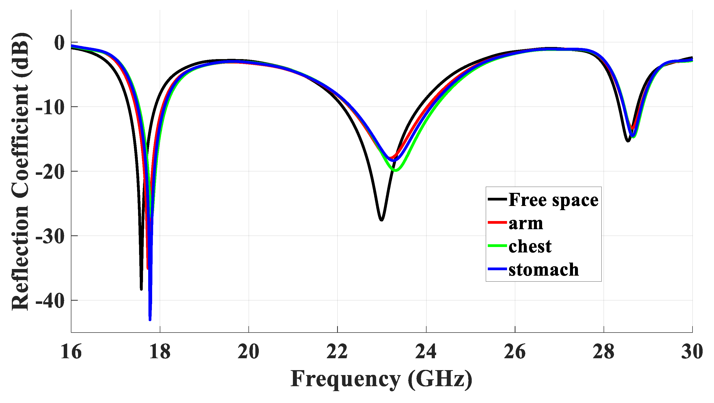
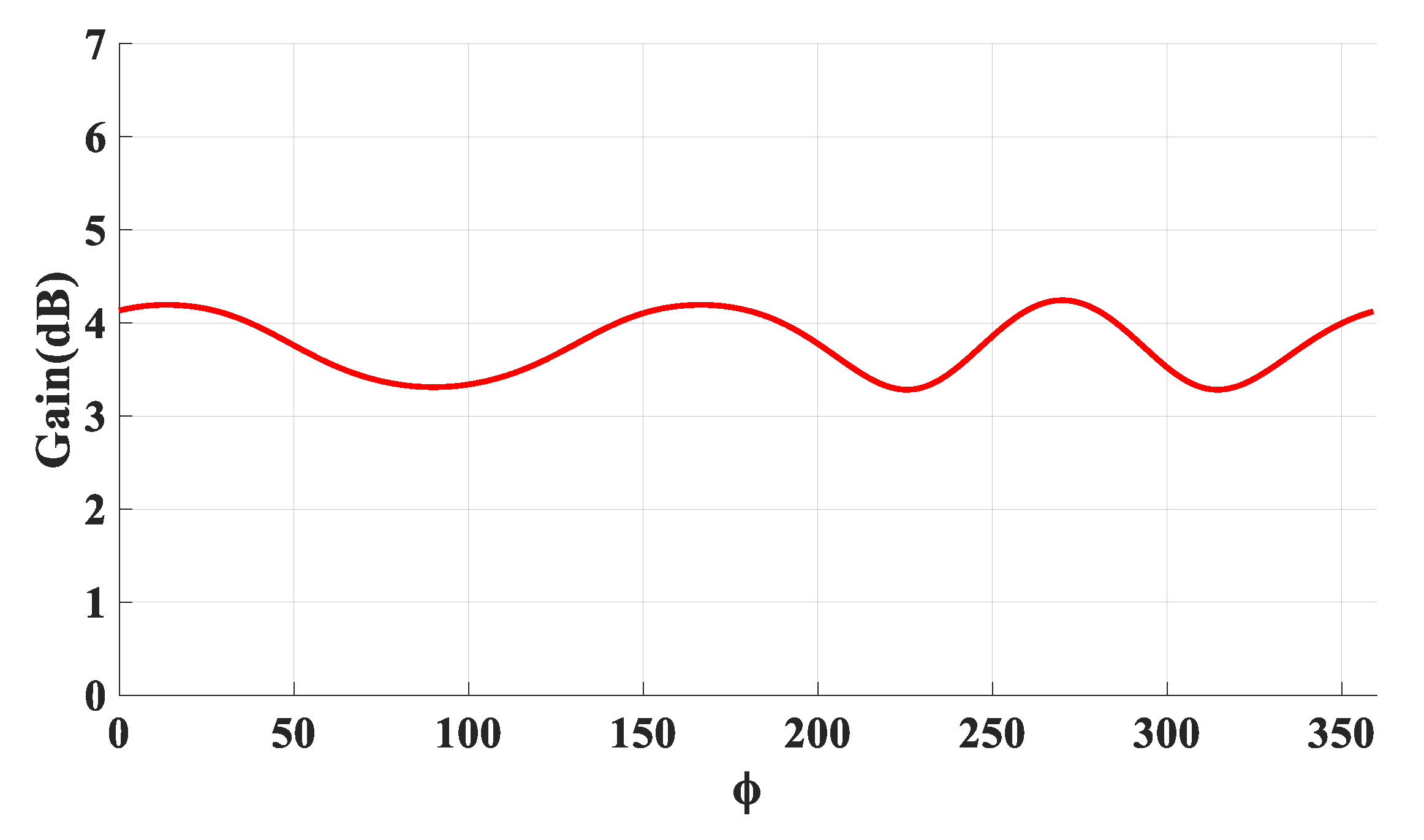
5. DRA Performance Next to a Human Body
6. Measured Results
7. Conclusions
Author Contributions
Funding
Institutional Review Board Statement
Informed Consent Statement
Data Availability Statement
Acknowledgments
Conflicts of Interest
References
- Chowdhury, M.Z.; Shahjalal, M.; Ahmed, S.; Jang, Y.M. 6G wireless communication systems: Applications, requirements, technologies, challenges, and research directions. IEEE Open J. Commun. Soc. 2020, 1, 957–975. [Google Scholar] [CrossRef]
- Abdulmajid, A.A.; Khalil, Y.; Khamas, S. Higher-order-mode circularly polarized two-layer rectangular dielectric resonator antenna. IEEE Antennas Wirel. Propag. Lett. 2018, 17, 1114–1117. [Google Scholar] [CrossRef]
- Meher, P.R.; Behera, B.R.; Mishra, S.K.; Althuwayb, A.A. A chronological review of circularly polarized dielectric resonator antenna: Design and developments. Int. J. RF Microw. Comput. -Aided Eng. 2021, 31, e22589. [Google Scholar] [CrossRef]
- Guha, D.; Banerjee, A.; Kumar, C.; Antar, Y.M. Higher order mode excitation for high-gain broadside radiation from cylindrical dielectric resonator antennas. IEEE Trans. Antennas Propag. 2011, 60, 71–77. [Google Scholar] [CrossRef]
- Rappaport, T.S.; MacCartney, G.R.; Samimi, M.K.; Sun, S. Wideband millimeter-wave propagation measurements and channel models for future wireless communication system design. IEEE Trans. Commun. 2015, 63, 3029–3056. [Google Scholar] [CrossRef]
- Liu, Y.; Yagoub, M.C. Compact, Broadband, and Omnidirectional Antenna Array for Millimeter-Wave Communication Systems. J. Microw. Optoelectron. Electromagn. Appl. 2021, 20, 297–306. [Google Scholar] [CrossRef]
- Maurya, N.K.; Ammann, M.J.; Mcevoy, P. Series-fed Omnidirectional mm-Wave Dipole Array. IEEE Trans. Antennas Propag. 2023, 71, 1330–1336. [Google Scholar] [CrossRef]
- Zou, L.; Abbott, D.; Fumeaux, C. Omnidirectional cylindrical dielectric resonator antenna with dual polarization. IEEE Antennas Wirel. Propag. Lett. 2012, 11, 515–518. [Google Scholar] [CrossRef]
- Pan, Y.M.; Zheng, S.Y.; Li, W. Dual-band and dual-sense omnidirectional circularly polarized antenna. IEEE Antennas Wirel. Propag. Lett. 2014, 13, 706–709. [Google Scholar] [CrossRef]
- Hu, P.F.; Pan, Y.M.; Leung, K.W.; Zhang, X.Y. Wide-/dual-band omnidirectional filtering dielectric resonator antennas. IEEE Trans. Antennas Propag. 2018, 66, 2622–2627. [Google Scholar] [CrossRef]
- Fang, X.S.; Leung, K.W. Design of wideband omnidirectional two-layer transparent hemispherical dielectric resonator antenna. IEEE Trans. Antennas Propag. 2014, 62, 5353–5357. [Google Scholar] [CrossRef]
- Lai, J.; Wang, J.; Zhao, K.; Jiang, H.; Chen, L.; Wu, Z.; Liu, J. Design of a dual-polarized omnidirectional dielectric resonator antenna for capsule endoscopy system. IEEE Access 2021, 9, 14779–14786. [Google Scholar] [CrossRef]
- Pan, Y.M.; Leung, K.W.; Lu, K. Omnidirectional linearly and circularly polarized rectangular dielectric resonator antennas. IEEE Trans. Antennas Propag. 2011, 60, 751–759. [Google Scholar] [CrossRef]
- Leung, K.W.; Pan, Y.M.; Fang, X.S.; Lim, E.H.; Luk, K.-M.; Chan, H.P. Dual-function radiating glass for antennas and light covers—Part I: Omnidirectional glass dielectric resonator antennas. IEEE Trans. Antennas Propag. 2012, 61, 578–586. [Google Scholar] [CrossRef]
- Zou, M.; Pan, J. Investigation of resonant modes in wideband hybrid omnidirectional rectangular dielectric resonator antenna. IEEE Trans. Antennas Propag. 2015, 63, 3272–3275. [Google Scholar] [CrossRef]
- Zou, M.; Pan, J.; Yang, D.; Xiong, G. Investigation of dual-band omnidirectional rectangular dielectric resonator antenna. J. ElEctromagnEtic WavEs Appl. 2016, 30, 1407–1416. [Google Scholar] [CrossRef]
- Li, W.; Leung, K.W.; Yang, N. Omnidirectional dielectric resonator antenna with a planar feed for circular polarization diversity design. IEEE Trans. Antennas Propag. 2018, 66, 1189–1197. [Google Scholar] [CrossRef]
- Yang, N.; Leung, K.W. Size reduction of omnidirectional cylindrical dielectric resonator antenna using a magnetic aperture source. IEEE Trans. Antennas Propag. 2019, 68, 3248–3253. [Google Scholar] [CrossRef]
- Yang, N.; Leung, K.W. Compact cylindrical pattern-diversity dielectric resonator antenna. IEEE Antennas Wirel. Propag. Lett. 2019, 19, 19–23. [Google Scholar] [CrossRef]
- Fang, X.S.; Weng, L.P.; Sun, Y.-X. Slots-coupled omnidirectional circularly polarized cylindrical glass dielectric resonator antenna for 5.8-GHz WLAN application. IEEE Access 2020, 8, 204718–204727. [Google Scholar] [CrossRef]
- Fang, X.S.; Weng, L.P.; Fan, Z. Design of the Wideband and Low-Height Omnidirectional Cylindrical Dielectric Resonator Antenna Using Arced-Apertures Feeding. IEEE Access 2023, 11, 20128–20135. [Google Scholar] [CrossRef]
- Pan, Y.M.; Leung, K.W.; Lu, K. Study of resonant modes in rectangular dielectric resonator antenna based on radar cross section. IEEE Trans. Antennas Propag. 2019, 67, 4200–4205. [Google Scholar] [CrossRef]
- Keyrouz, S.; Caratelli, D. Dielectric resonator antennas: Basic concepts, design guidelines, and recent developments at millimeter-wave frequencies. Int. J. Antennas Propag. 2016, 2016, 6075680. [Google Scholar] [CrossRef]
- Petosa, A.; Simons, N.; Siushansian, R.; Ittipiboon, A.; Cuhaci, M. Design and analysis of multisegment dielectric resonator antennas. IEEE Trans. Antennas Propag. 2000, 48, 738–742. [Google Scholar] [CrossRef]
- Mongia, R.K.; Ittipiboon, A. Theoretical and experimental investigations on rectangular dielectric resonator antennas. IEEE Trans. Antennas Propag. 1997, 45, 1348–1356. [Google Scholar] [CrossRef]
- Row, J.-S. The design of a squarer-ring slot antenna for circular polarization. IEEE Trans. Antennas Propag. 2005, 53, 1967–1972. [Google Scholar] [CrossRef]
- Gao, G.; Wang, S.; Zhang, R.; Yang, C.; Hu, B. Flexible EBG-backed PIFA based on conductive textile and PDMS for wearable applications. Microw. Opt. Technol. Lett. 2020, 62, 1733–1741. [Google Scholar] [CrossRef]
- Xu, R.; Zhu, H.; Yuan, J. Electric-field intrabody communication channel modeling with finite-element method. IEEE Trans. Biomed. Eng. 2010, 58, 705–712. [Google Scholar]
- Hamed, T.; Maqsood, M. SAR calculation & temperature response of human body exposure to electromagnetic radiations at 28, 40 and 60 GHz mmWave frequencies. Prog. Electromagn. Res. M 2018, 73, 47–59. [Google Scholar]
- Lak, A.; Adelpour, Z.; Oraizi, H.; Parhizgar, N. Design and SAR assessment of three compact 5G antenna arrays. Sci. Rep. 2021, 11, 21265. [Google Scholar] [CrossRef]
- T-Ceram s.r.o. Available online: http://www.t-ceram.com/ (accessed on 3 January 2023).
- Wrekin Circuits, Ltd. Available online: https://www.wrekin-circuits.co.uk/ (accessed on 6 December 2022).
- Abdou, T.S.; Saad, R.; Khamas, S.K. A Circularly Polarized mmWave Dielectric-Resonator-Antenna Array for Off-Body Communications. Appl. Sci. 2023, 13, 2002. [Google Scholar] [CrossRef]
- Alanazi, M.D.; Khamas, S.K. Wideband mm-wave hemispherical dielectric resonator antenna with simple alignment and assembly procedures. Electronics 2022, 11, 2917. [Google Scholar] [CrossRef]
- UKRI National Millimetre Wave Facility. Available online: https://www.sheffield.ac.uk/mm-wave/ (accessed on 6 October 2022).
- Ur-Rehman, M.; Adekanye, M.; Chattha, H.T. Tri-band millimetre-wave antenna for body-centric networks. Nano Commun. Netw. 2018, 18, 72–81. [Google Scholar] [CrossRef]
- Chahat, N.; Zhadobov, M.; Le Coq, L.; Sauleau, R. Wearable endfire textile antenna for on-body communications at 60 GHz. IEEE Antennas Wirel. Propag. Lett. 2012, 11, 799–802. [Google Scholar] [CrossRef]
- Ur-Rehman, M.; Malik, N.A.; Yang, X.; Abbasi, Q.H.; Zhang, Z.; Zhao, N. A low profile antenna for millimeter-wave body-centric applications. IEEE Trans. Antennas Propag. 2017, 65, 6329–6337. [Google Scholar] [CrossRef]
- Wagih, M.; Weddell, A.S.; Beeby, S. Millimeter-wave textile antenna for on-body RF energy harvesting in future 5G networks. In Proceedings of 2019 IEEE Wireless Power Transfer Conference (WPTC), London, UK, 18–21 June 2019; pp. 245–248. [Google Scholar]
- Khan, M.M.; Islam, K.; Alam Shovon, M.N.; Baz, M.; Masud, M. Design of a novel 60 GHz millimeter wave Q-slot antenna for body-centric communications. Int. J. Antennas Propag. 2021, 2021, 9795959. [Google Scholar] [CrossRef]
- Rahman, H.A.; Khan, M.M.; Baz, M.; Masud, M.; AlZain, M.A. Novel compact design and investigation of a super wideband millimeter wave antenna for body-centric communications. Int. J. Antennas Propag. 2021, 2021, 8725263. [Google Scholar] [CrossRef]


| Frequency (GHz) | Resonance Mode |
|---|---|
| 17.5 | |
| 28.5 | , |
| Tissue | Skin | Fat | Muscle |
|---|---|---|---|
| Relative permittivity | 16.55 | 6.09 | 25.43 |
| Loss tangent | 0.2818 | 0.1454 | 0.242 |
| Density (kg/m3) | 1109 | 911 | 1090 |
| Ref | Antenna Type | Frequency GHz | Size (λ3) 1 | S11 Bandwidth (%) | On-Body Gain dBi | On-Body ηrad (%) |
|---|---|---|---|---|---|---|
| [36] | Slotted patch | 28, 38, 61 | 1.04 × 1.02 × 0.052 | 3, 1, 1.5 | 8.1, 8.3, 7 | 54, 60, 58 |
| [37] | Yagi array | 60 | 3.2 × 1.6 × 0.04 | 15 | 9 | 41 |
| [38] | Patch-like | 60 | 2.8 × 2.1 × 0.23 | 16.3 | 12 | 63 |
| [39] | Textile | 28 | 1.89 × 0.87 × 0.147 | 33 | 6.6 | 53.5 |
| [40] | Q Slot | 60 | 2.58 × 2.8 × 0.32 | 12 | 8 | 56.68 |
| [41] | Patch-like | 60 | 1.6 × 1.02 × 0.23 | - | 5.4 | 62.2 |
| This work | RDRA | 17.5, 23, 28.5 | 1.19 × 1.19 × 0.16 | 3.4, 7.7, 1.9 | 7.3, 6.8, 5.8 | 90, 87, 84 |
Disclaimer/Publisher’s Note: The statements, opinions and data contained in all publications are solely those of the individual author(s) and contributor(s) and not of MDPI and/or the editor(s). MDPI and/or the editor(s) disclaim responsibility for any injury to people or property resulting from any ideas, methods, instructions or products referred to in the content. |
© 2023 by the authors. Licensee MDPI, Basel, Switzerland. This article is an open access article distributed under the terms and conditions of the Creative Commons Attribution (CC BY) license (https://creativecommons.org/licenses/by/4.0/).
Share and Cite
Abdou, T.S.; Khamas, S.K. A Multiband Millimeter-Wave Rectangular Dielectric Resonator Antenna with Omnidirectional Radiation Using a Planar Feed. Micromachines 2023, 14, 1774. https://doi.org/10.3390/mi14091774
Abdou TS, Khamas SK. A Multiband Millimeter-Wave Rectangular Dielectric Resonator Antenna with Omnidirectional Radiation Using a Planar Feed. Micromachines. 2023; 14(9):1774. https://doi.org/10.3390/mi14091774
Chicago/Turabian StyleAbdou, Tarek S., and Salam K. Khamas. 2023. "A Multiband Millimeter-Wave Rectangular Dielectric Resonator Antenna with Omnidirectional Radiation Using a Planar Feed" Micromachines 14, no. 9: 1774. https://doi.org/10.3390/mi14091774
APA StyleAbdou, T. S., & Khamas, S. K. (2023). A Multiband Millimeter-Wave Rectangular Dielectric Resonator Antenna with Omnidirectional Radiation Using a Planar Feed. Micromachines, 14(9), 1774. https://doi.org/10.3390/mi14091774