Article

Theoretical and Experimental Investigation of Surface Textures in Vibration-Assisted Micro Milling

1
Key Laboratory of Equipment Design and Manufacturing Technology, Tianjin University, Tianjin 300072, China
2
Pen-Tung Sah Institute of Micro-Nano Science and Technology, Xiamen University, Xiamen 361102, China
3
School of Engineering & Built Environment, Gold Coast Campus, Griffith University, Southport, QLD 4222, Australia
*
Authors to whom correspondence should be addressed.
Micromachines 2024, 15(1), 139; https://doi.org/10.3390/mi15010139
Submission received: 20 December 2023 / Revised: 11 January 2024 / Accepted: 15 January 2024 / Published: 16 January 2024
(This article belongs to the Special Issue Research Progress of Ultra-Precision Micro-nano Machining)

Abstract

:
Vibration-assisted micro milling is a promising technique for fabricating engineered mi-cro-scaled surface textures. This paper presents a novel approach for theoretical modeling of three-dimensional (3D) surface textures produced by vibration-assisted micro milling. The proposed model considers the effects of tool edge geometry, minimum uncut chip thickness (MUCT), and material elastic recovery. The surface texture formation under different machining parameters is simulated and analyzed through mathematical modeling. Two typical surface morphologies can be generated: wave-type and fish scale-type textures, depending on the phase difference between tool paths. A 2-degrees-of-freedom (2-DOF) vibration stage is also developed to provide vibration along the feed and cross-feed directions during micro-milling process. Micro-milling experiments on copper were carried out to verify the ability to fabricate controlled surface textures using the vibration stage. The simulated and experimentally generated surfaces show good agreement in geometry and dimensions. This work provides an accurate analytical model for vibration-assisted micro-milling surface generation and demonstrates its feasibility for efficient, flexible texturing.

1. Introduction

The growing prevalence of engineered textured surfaces can be attributed to their ability to enhance the performance of component surfaces in various application areas, such as tribology [1], wettability [2], optics [3], bioengineering, and thermal properties [4,5]. The widespread incorporation of surface texturing across various industries has motivated the pursuit of sophisticated manufacturing techniques that can effectively create intricate surface morphologies. The repertoire of established surface texturing techniques includes focused ion beam machining [6,7], electron beam machining [8], lithography, laser ablation, and micro-rolling [9]. However, restrictions have been identified regarding economic feasibility, process efficiency, material compatibility, geometric complexity, and scalability.
For many years, micromachining technology has dedicated significant efforts to investigating the microscopic scale material removal process [10,11]. Recently, vibration-assisted micro machining has arisen as a promising approach for accurate and flexible surface texturing [12,13,14]. Multiple advantages and improvements have been proved, such as reduced cutting forces [15], extended tool life, minimized burr formation, improved surface quality [16], and the ability to machine hardened metals and ceramics [17,18]. Vibration-assisted machining was initially designed to enhance the machinability of challenging materials, and later has proven to be adept at surface texturing. Among them, vibration-assisted micro milling has emerged as an efficient method for embedding surface textures on machined workpieces like aluminum alloy, copper alloy, and titanium alloy [19]. This technique overcomes limitations of existing approaches with the benefits of cost-effectiveness, high efficiency, and environmental friendliness. Engineered surface textures produced by vibration-assisted micro milling provide multifaceted performance enhancements, including reduced adhesion friction [20], smoothed lubricated sliding, upgraded wear resistance [21], controlled surface wettability [22], and tuned optical characteristics [23].
According to the vibration application types, vibration-assisted machining can generally be implemented in two ways: applying vibration to the tool and the workpiece. Since the cutter typically rotates at an extremely high speed during the micro-milling process, the second method of applying vibration to the workpiece is generally selected. Constructing a flexible stage is necessary to fix the workpiece to implement the method mentioned above [24]. Börner et al. [25] designed a cross-converter to deliver the vibration motion to the workpiece. Then, they discussed the application of ultrasonic vibration-assisted machining in end-milling processes to generate predefined microstructures. Ding et al. [26] described a 2-degrees-of-freedom (2-DOF) non-resonant flexible stage to fix the workpiece, and two piezoelectric actuators were symmetrically distributed to provide the vibration along the feed and cross-feed directions.
In 3D surface texture modeling, Chen et al. [27,28] proposed a model based on homogenous matrices transformation, establishing the surface profile according to the tool tip’s shape. Lv et al. [29] developed a 3D vibration-assisted milling model for generating various structured surfaces by employing orthogonal spiral and multi-body kinematics theories. Yuan et al. [30] presented a vibration-assisted ball-end milling method for generating various surface textures using a non-resonant vibrator. Their model considered the tool trajectory in the vibration-assisted ball-end milling process, the quantitative relationships between the generated dimple geometric parameters, and the cutting and vibration condition. However, these models overlook the size effects inherent to the micro-cutting process, including the minimum uncut chip thickness (MUCT) phenomenon and material elastic recovery. This omission negatively impacts modeling precision.
To address the aforementioned issues, this paper introduces a novel method for forming surface texture in vibration-assisted micro milling, taking into account the influence of the tooltip geometry, MUCT, and material elastic recovery. The study aims to model the bottom side of the machined slot. Section 2 introduces the surface texture formation in the micro-milling process with different machining and vibration parameters. Section 3 presents the development of a novel 2-DOF vibration stage to realize the vibration during the milling process. Then, the vibration-assisted milling experiments are carried out to verify the proposed surface texture formation method in Section 4. Finally, the conclusion is made in Section 5.

2. Surface Texture Modeling

2.1. Tool Trajectory Modeling

To precisely establish the surface texture of vibration-assisted milling, the mathematical modeling of the conventional micro-milling surface should be first analyzed. Due to being most widely utilized in the micro-milling process, a micro-end-milling cutter with two flutes is employed on discussing for convenience.
Figure 1a shows a full slot micro end-milling operation for an end-mill with a two-flute cutter in the Cartesian coordinate system, in which, the X-axis and Y-axis represent the feed direction and cross-feed direction, respectively. ω is the spindle speed, R is the tool radius, and φ is the spindle phase angle. Figure 1b illustrates the tool trajectory of the micro-milling process, where the horizontal and vertical coordinates of points on the milling trajectory (x, y) can be calculated as follows:
{ x = f t + R cos ( ω t + π ( z i 1 ) + φ ) y = R sin ( ω t + π ( z i 1 ) + φ )
where zi is the ith cutter flute, f is the feed rate, and t is the cutting time.

2.2. Three-Dimensional Micro-Milling Surface Modeling

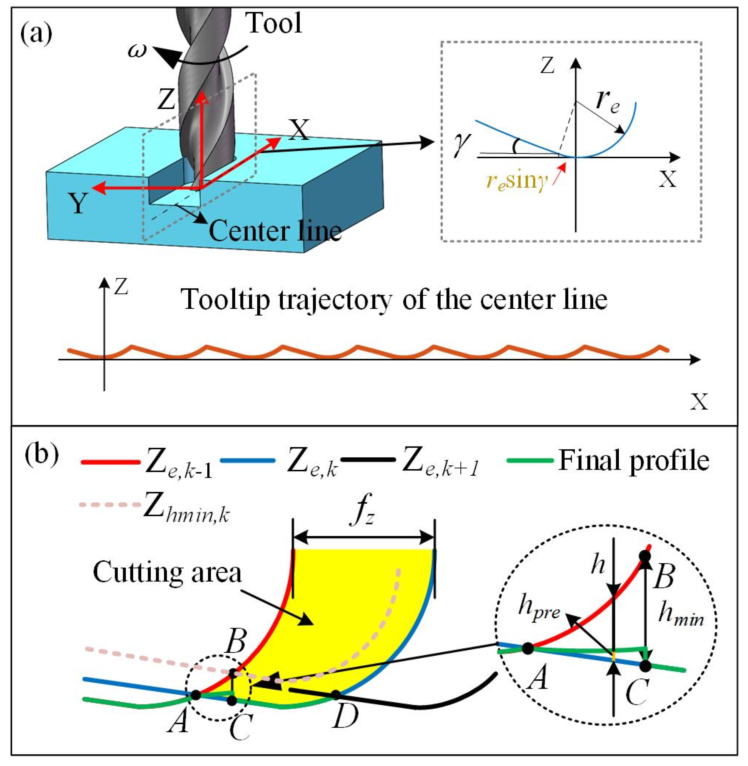
Due to the micro dimension in the micro-milling process, the surface texture will be impacted significantly by the geometry of the tooltip, MUCT, and the material elastic recovery. Therefore, these effects should be considered in the surface texture modeling. The surface profile corresponding to the centerline of the slot floor is selected to discuss for convenience. Figure 2 illustrates the tooltip trajectory and machined surface profile at the centerline, with a close-up view of the bottom tool edge. In order to simplify the model, the tool edge is considered as an arc with a tool edge radius of re, and the tool flank face is considered as a plane with a clearance angle of γ. Therefore, the profile height corresponding to the x coordinate can be defined as Equation (2):
Z e = { r e r e 2 x 2 ,   x > r e sin γ r e r e cos γ [ x + r e sin γ ] tan γ ,   x r e sin γ
In micro-milling processing, an uncut chip thickness less than the MUCT results in no chip formation. To evaluate chip formation, a critical line for MUCT can be defined as follows [31]:
Ζ h min = { ( r e h min ) 2 x 2 , x > ( r e h min ) sin γ ( r e h min ) cos γ [ x + ( r e h min ) sin γ ] tan γ , x ( r e h min ) sin γ
Based on the tool edge geometry considering the effect of MUCT and material elastic recovery, the generated surface profile can be depicted in Figure 2b. Where fz, h, hmin, and hpre represent the feed per tooth, uncut chip thickness, MUCT, and the material elastic recovery height. hpre can be calculated as hpre = h·Pe, where Pe is the material elastic recovery ratio. The profile of the current flute (Ze, k) intersects point A and point D with that of the previous flute (Ze, k−1) and that of the successive flute (Ze, k+1), respectively. The yellow area represents the cutting area. In the micro-milling process, the critical line for MUCT of current flute (Zhmin, k) intersects with the profile of the previous flute (Ze, k−1) at point B, supposing that point B corresponding to the profile of the current flute (Ze, k) is recorded as point C, where BC is equal to the MUCT. On the left of point C, there is no chip formation due to the uncut chip thickness being less than the MUCT. The final profile in the BC zone is generated by elastic recovery of material after the current flute (Ze, k) passes the surface. The elastic recovery height could be calculated in our previous work according to Ref. [31]. For the right of point C, the surface material between point C and point D is removed by the successive flute (Ze, k+1), and the final profile generated (green line) coincides with the CD profile of the flute (Ze, k). This process of final profile in the AD zone is repeated, and the surface material can be removed entirely in the subsequent stage. Finally, the final surface profile is formed along the centerline of the slot floor until all flutes exit the workpiece, and the final surface profile can be expressed as follows:
Ζ f = { Ζ h min + ( 1 P e ) ( Ζ e , k Ζ h min ) Ζ e , k h h min h > h min
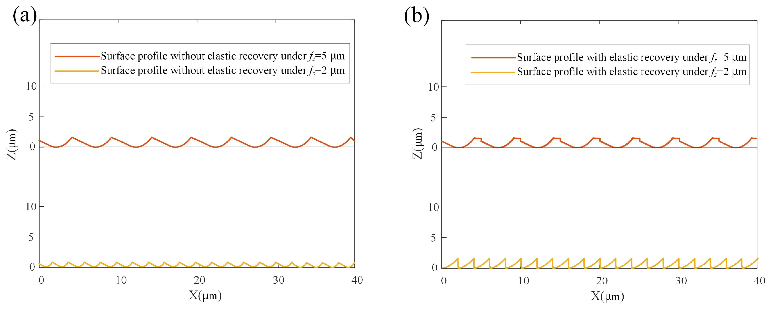
The feed per tooth significantly influences the machined surface profile. In a previous work, by comparing the feed per tooth and minimum uncut chip thickness in the milling process, two typical surface profiles were identified [31]. If fz > MUCT, a wave-type profile is formed; meanwhile, if fz < MUCT, a spike-type profile is produced. A set of micro-milling condition and cutting parameters are listed in Table 1. Under this condition with MUCT determined as 2.4 μm, two case studies for the surface profiles with the feed per tooth of 2 μm/tooth and 5 μm/tooth were conducted. A comparison of surface profiles with and without elastic recovery effects is illustrated in Figure 3a,b.
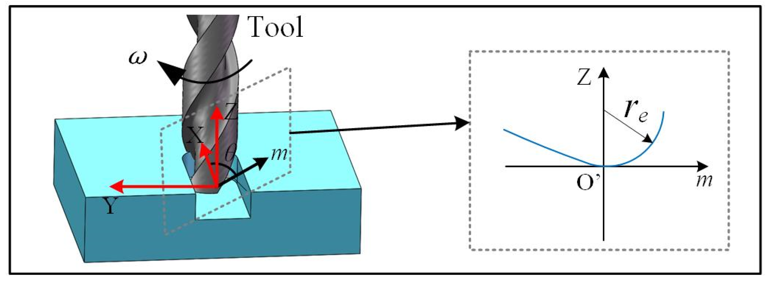
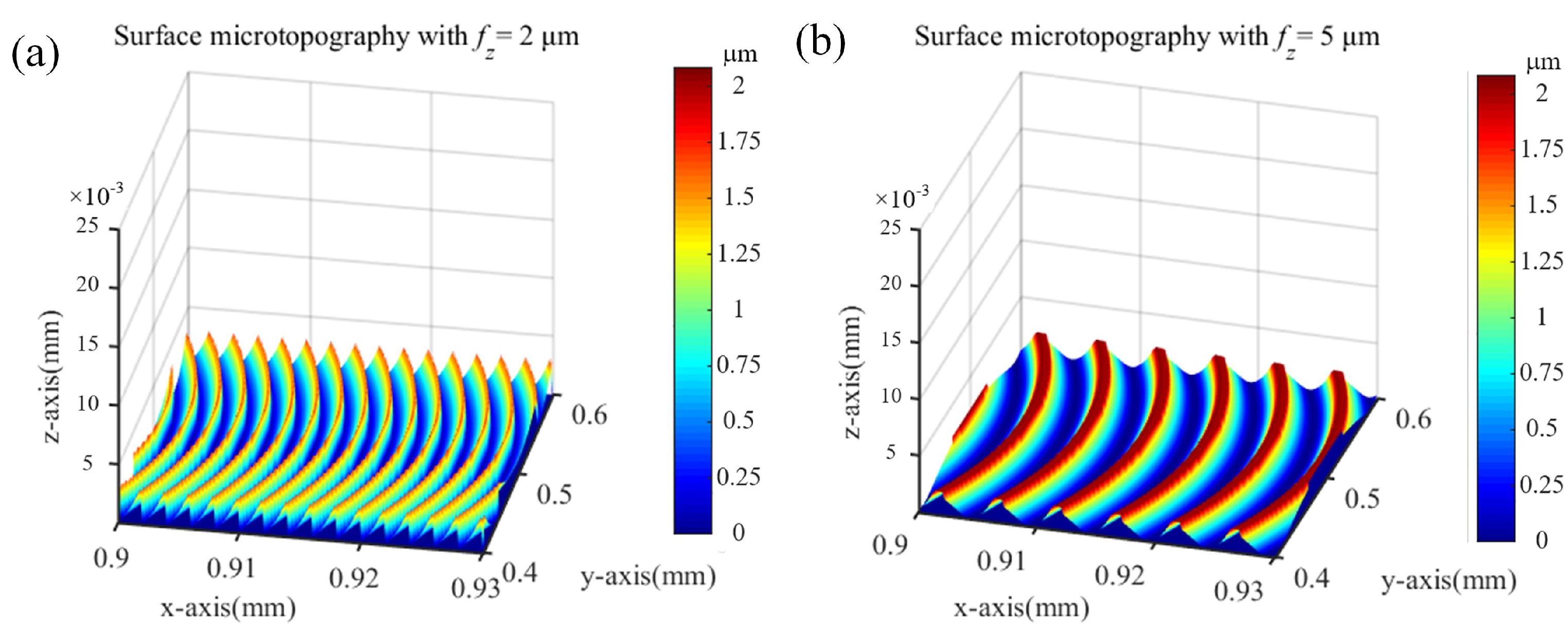
To derive the 3D surface texture, the 2D profile needs to be transferred based on the tool trajectory outlined in Equation (1). As shown in Figure 4, at a given time t, the tooltip has an angel θt with respect to the x coordinate. The coordinate of a point on the tooltip can be designated as (xm, ym, zm). If the elastic recovery is not considered, the surface profile generated by the tooltip can be calculated using Equation (5):
{ θ t = ω t + π ( z i 1 ) + φ x m = f t + ( R + m ) cos θ , m < r e y m = ( R + m ) sin θ , m < r e z m = Z e ( m ) , m < r e
where m is equivalent with the x coordinate in Equation (2). By considering the elastic recovery as derived in Equations (3) and (4), the 3D surface texture could be established, as shown in Figure 5a,b.

2.3. Vibration-Assisted Micro-Milling Texture Modeling

According to the dimension of the vibration applied, vibration-assisted milling can be commonly classified into two types: 1-DOF vibration and 2-DOF vibration. In 1-DOF vibration-assisted micro-milling, vibration is delivered in either the feed or cross-feed direction, facilitating the movement of the workpiece in a single direction. In 2-DOF vibration-assisted milling, vibration co-occurs in the feed and cross-feed directions, causing an elliptical motion of the workpiece in a plane. When the 2-DOF vibration is applied to the workpiece, its trajectory could be calculated by Equation (6):
{ x w = A sin ( 2 π f a t + θ x ) y w = B sin ( 2 π f a t + θ y )
where A and B are the vibration amplitudes, fa is the vibration frequency, and θx and θy are the phase angles in the x and y directions, respectively. As for a two-flute cutter, the relative displacement (x, y) of the tooltip to the workpiece in 2-DOF vibration-assisted milling can be obtained from Equations (1) and (7):
{ x = f t + R cos [ ω t + π ( z i 1 ) + φ ] + A sin ( 2 π f a t + θ x ) y = R sin [ ω t + π ( z i 1 ) + φ ] + B sin ( 2 π f a t + θ y )
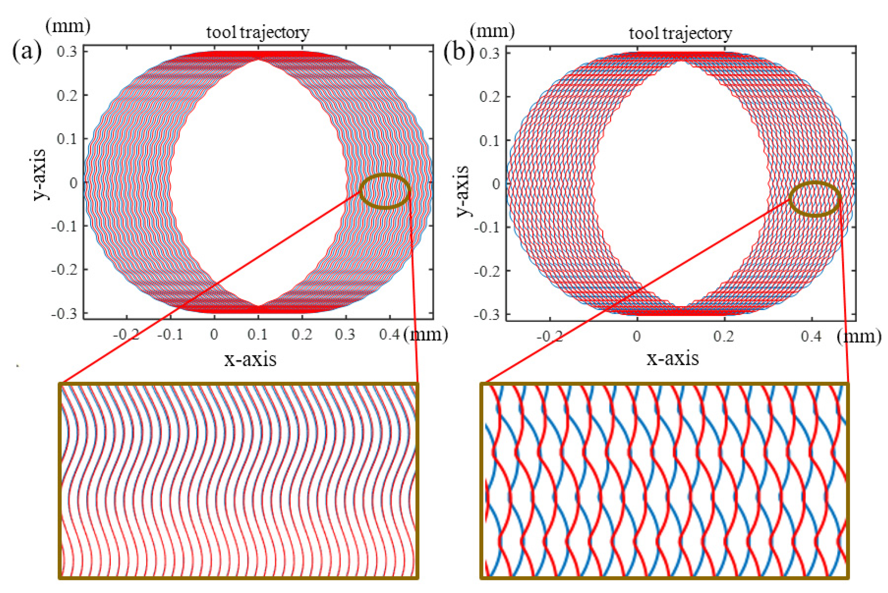
The essence of vibration-assisted milling is to apply high-frequency sinusoidal motion to the micro-milling trajectory, which changes the original micro-milling trajectory. Different phase angles result in differences in adjacent tooth trajectories, which can be combined into different surface morphologies. According to the micro-milling condition and vibration parameters presented in Table 2, it can be obtained that there are two typical surface morphologies. One is wave-type texture, which means that the surface morphology produced by adjacent flutes possesses the same phase angle, as shown in Figure 6a. Another is the fish-type texture, in which the phase difference between adjacent flutes is around 180 degrees, causing the surface morphology to interlock with each other, as shown in Figure 6b. The phase difference could be adjusted by changing the spindle speed and vibration frequencies. The conditions of the two cases to generate the above-mentioned two typical tool trajectories can be determined using Equation (8):
{ 60 f a · 2 π n Z = ( 2 i + 1 ) π , i = 1 , 2 , 3 ,   Wave   type   texture   generation 60 f a · 2 π n Z = ( 2 i ) π , i = 1 , 2 , 3 ,   Fish   type   texture   generation
where n is the spindle speed, and Z is the number of flutes.
The 3D surface texture is obtained by using the mathematical method of conventional milling outlined in Section 2.2. For a given time t, the tooltip possesses an angel θt with respect to the x coordinate. If the elastic recovery is not considered, but the 2-DOF vibration applied to the workpiece as in Equation (6) is included, the surface profile produced by the tooltip in Equation (3) can be updated to a new form as:
{ θ t = ω t + π ( z i 1 ) + φ x m = f t + ( R + m ) cos θ + A sin ( 2 π f a t + θ x ) , m < r e y m = ( R + m ) sin θ + B sin ( 2 π f a t + θ y ) , m < r e z m = Z e ( m ) , m < r e
where m is equivalent with the x coordinate in Equation (2).
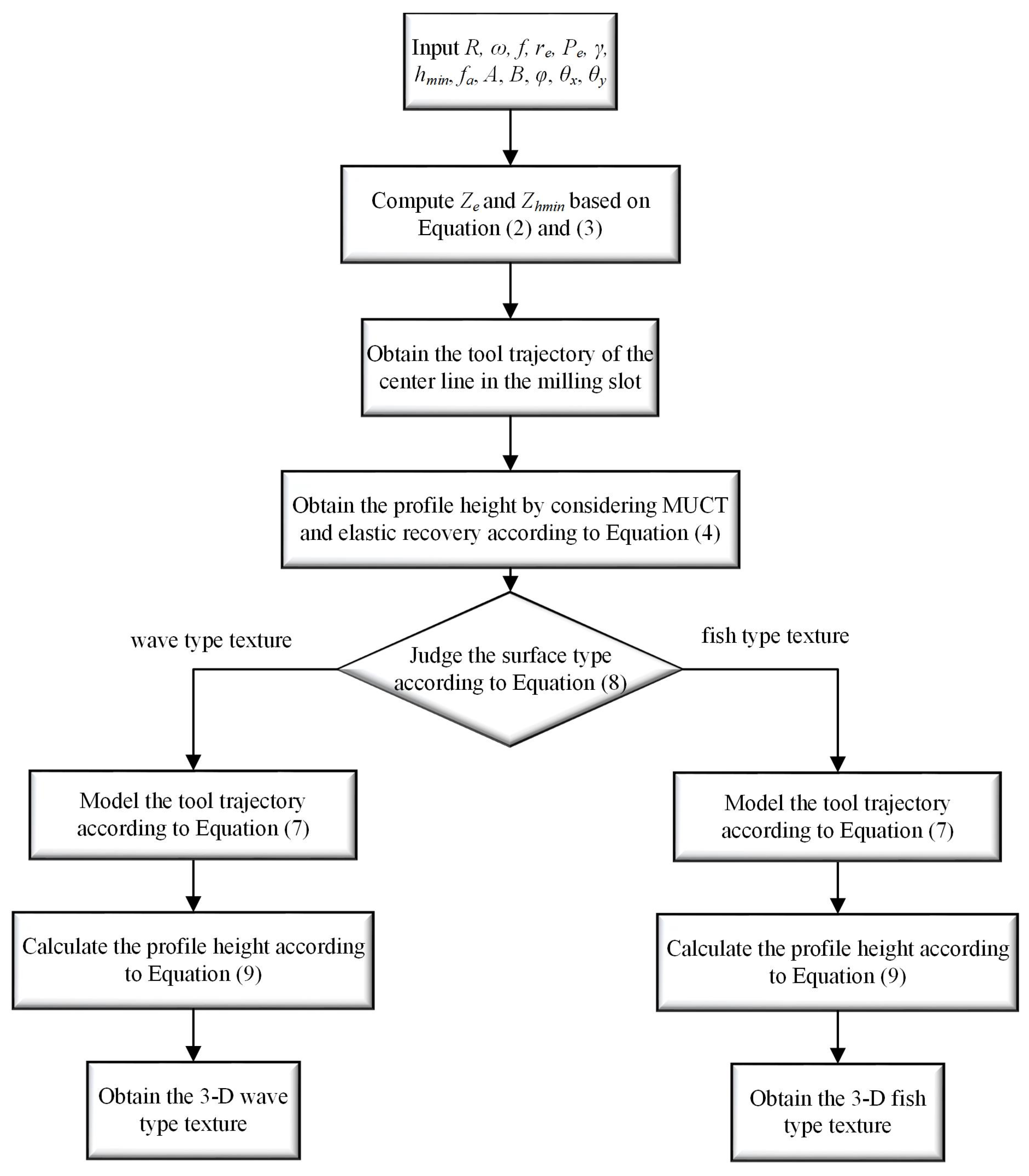
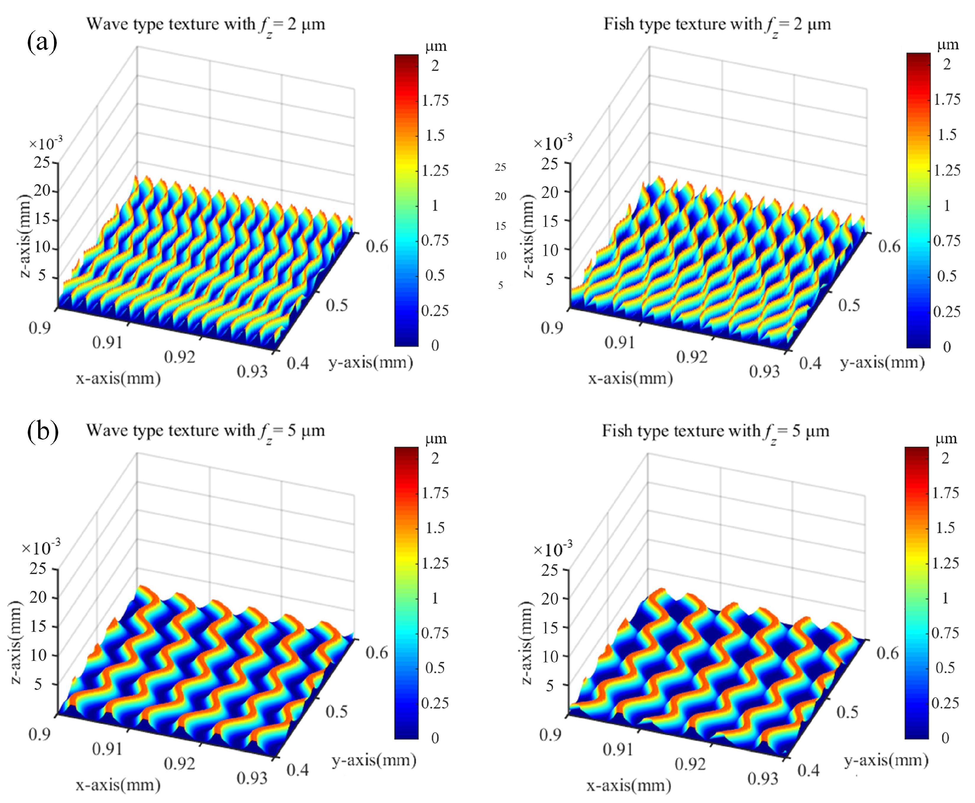
The flowchart for calculating the 3D surface texture is shown in Figure 7. By considering the elastic recovery as represented in Equations (3) and (4), the 3D surface textures of vibration-assisted milling under fz = 2 and 5 μm/tooth can be simulated, as shown in Figure 8a,b. According to the experiment conditions proposed in Equation (8), both wave and fish-type textures are derived, which proves the soundness of the analytical method.

3. Vibration-Stage Design and Optimization

3.1. Vibration-Stage Design

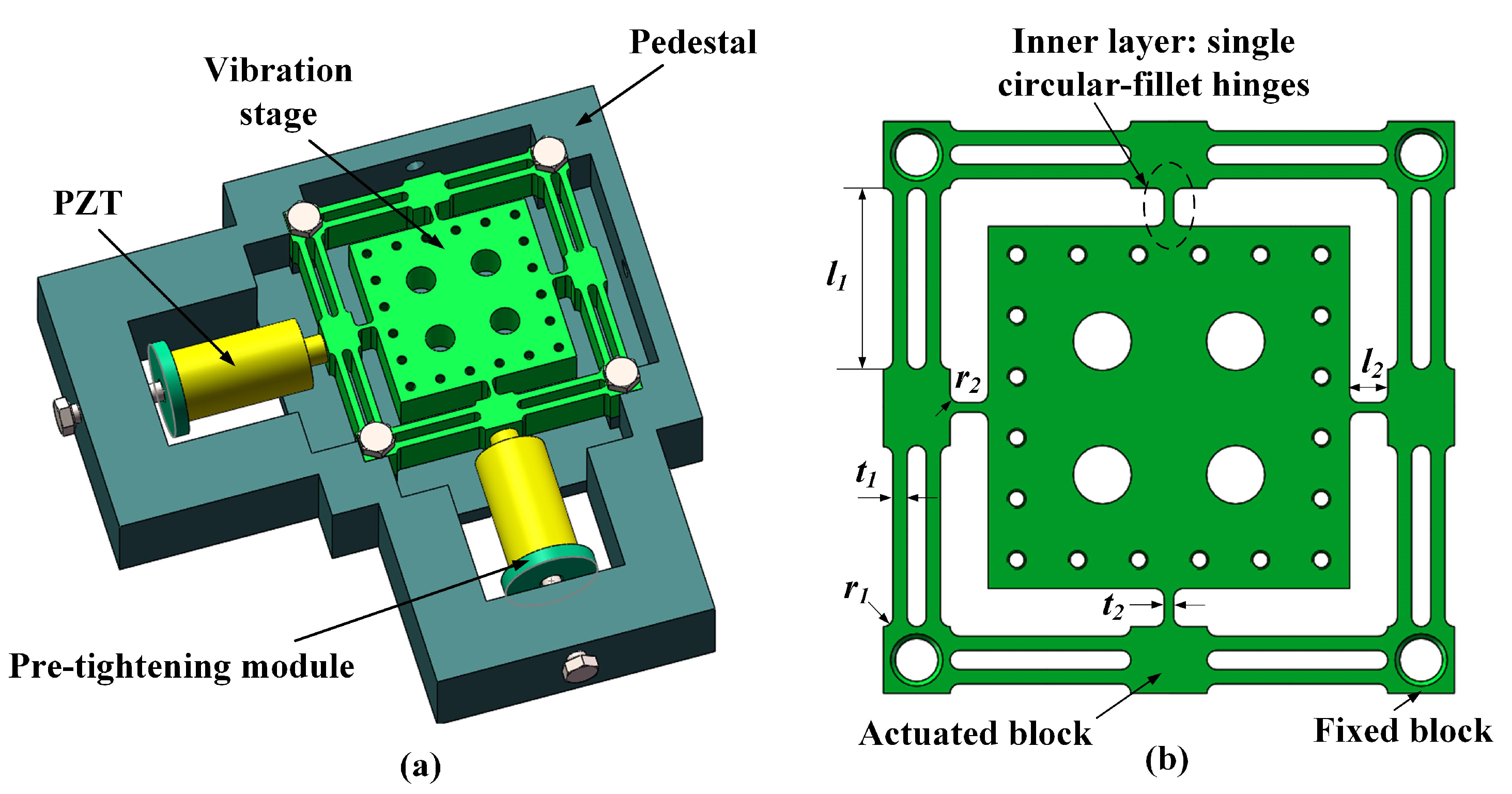
The basic structure of the proposed 2-DOF vibration-assisted platform is illustrated in Figure 9a, mainly consisting of a pair of piezoelectric actuators, a flexible stage, and a pedestal. To improve the assembly accuracy, the four corners of the flexible stage are positioned close to the pedestal. The schematic diagram of the flexible stage is shown in Figure 9b. To achieve the decoupling of two vibration directions, the whole structure is designed symmetrically, and a two-layer mechanism is utilized in the two-vibration direction. To further reduce the coupling effect, a novel kind of double-parallel flexure hinge is used as the outside framework of the stage due to the compression stiffness of the double-parallel flexure hinge being substantially higher than its rotational stiffness. The inner layer mechanism uses a single beam hinge to extend the mechanism’s vibration range. Additionally, circular-fillet hinges are employed throughout the construction. While increasing the motion precision, it could reduce the stress concentration.

3.2. Parameters Optimization

Flexible stages with large output displacement and high bandwidth are required to satisfy the demand for practical vibration-assisted milling. As the two most important parameters, the resonant frequency and compliance highly decide the bandwidth and output displacement of the flexible stage. Therefore, the resonant frequency and compliance are designed as optimization targets for structural parameters. The calculation method of compliance and the resonant frequency could be derived according to Ref. [32]. Based on the established theoretical model, parameter optimization of the 2-DOF stages is conducted to determine the detailed structural parameters. A typical suppression relationship exists between the two parameters, resulting in severe difficulty in the optimization process.
Based on the static and kinematic analysis results, the flexible stage’s performances are directly determined by the flexible hinges, including the inner and outer layer circular-fillet hinges. As shown in Figure 9b, the parameters of the hinges: fillet radiuses r1, r2, hinge lengths l1, l2, and widths t1, t2, are set as the optimization objections. The overall dimensions of the flexible stage are determined based on the milling machine’s working space [32]. Given the fixed dimensions of the fixed blocks and actuated blocks as illustrated in Figure 9b for the flexible stage, the parameters have the following relationship:
2 r 1 + t 1 = 3.5   m m 2 r 1 + l 1 = 19   m m 2 r 2 + l 2 = 4   m m
Therefore, the hinge widths of the outer-layer hinge t1, inner-layer hinge t2, and the fillet radius of the inner-layer hinge r2 can be modeled as the variable parameters in the parametric optimization process. The other parameters of the structure are given in Table 3. Due to the typical suppression relationship between the compliance and resonant frequency, the optimized objective function is defined as:
Q = k 1 ( C C 1 ) 2 + k 2 ( k 3 ( f f 1 ) ) 2
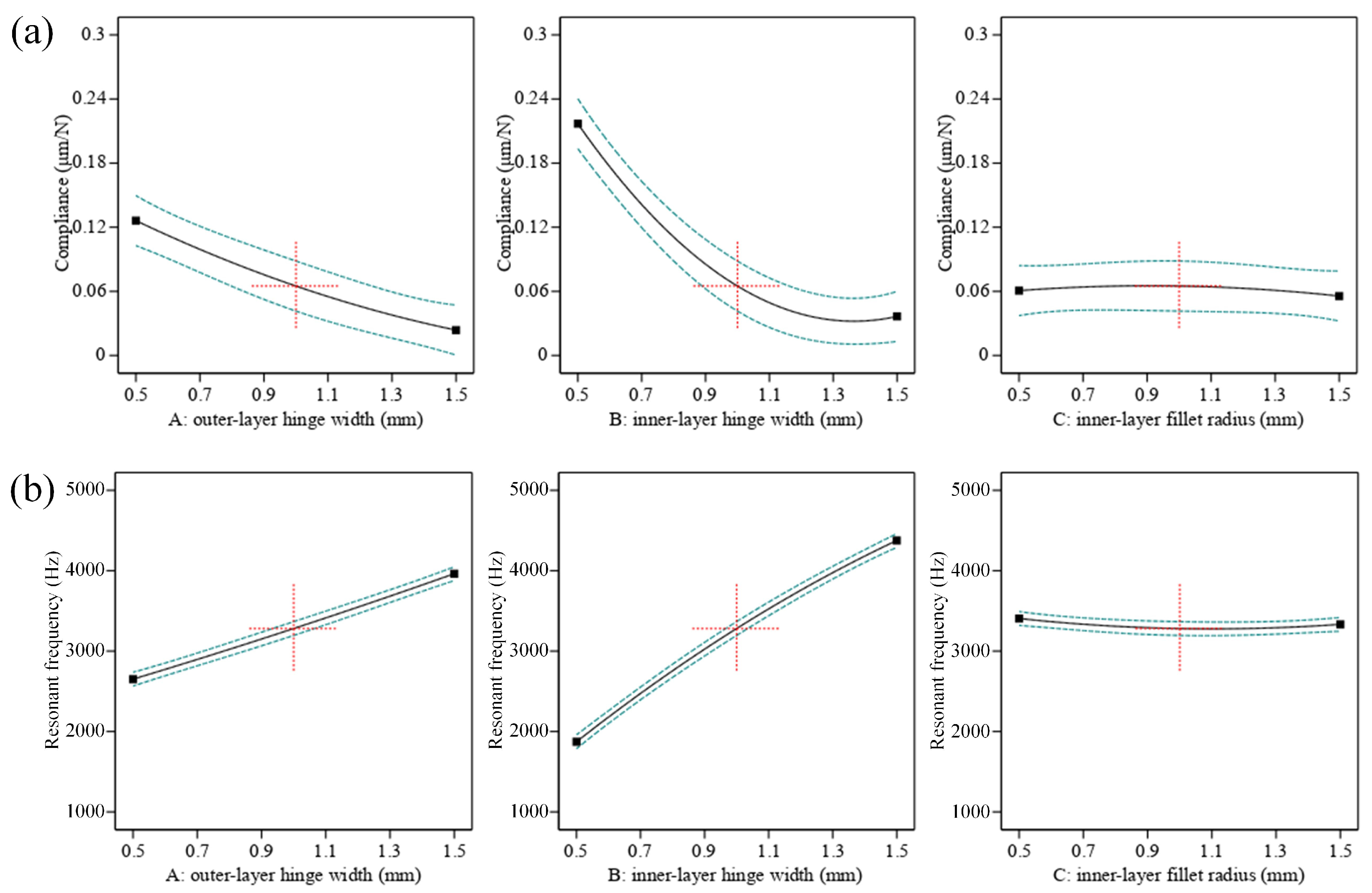
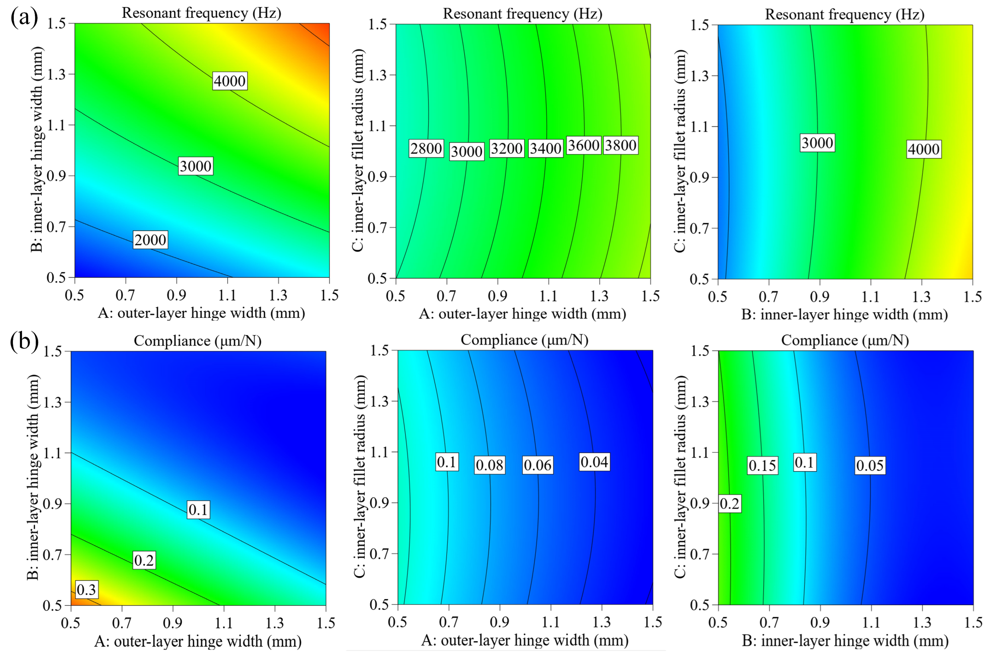
where C1 and f1 are the optimization objectives. k1, k2 are the weight factors and were set as k1 = 0.5 N/μm, k2 = 0.5 Hz−1. k3 is the balance factor, which can be defined as k3 = C1/f1. Al7075-T651 was adopted as the stage material, whose mechanical properties are shown in Table 4. According to the calculation results and experiment experience, the optimization objectives C1 and f1 were set as 0.1 μm/N and 3700 Hz. To guarantee the stage practicability of compliance and resonant frequency, the value of the three object parameters should be arranged in the range of 0.5–1.5 mm according to the experiment of the stage design. Subsequently, to ensure the integrity and accuracy of the database, each parameter was set as 0.5 mm, 1 mm, and 1.5 mm, resulting in 27 groups of combinations to be set as the initial data. The calculation results are shown in Table A1 in Appendix A. It can be observed that the 23rd group obtained the lowest value of Q, which means it has the closest data to the optimization objectives. In addition, the influence of parameters on compliance and frequency was analyzed based on the calculation results. Figure 10 shows the effect curve with one factor, while Figure 11 presents the influence contour with two factors. According to the graphs, it can be seen that with an increase in outer-layer hinge t1 and inner-layer hinge t2, the natural frequency gradually increases, and compliance presents a decreasing trend. At the same time, the fillet radius of the inner-layer hinge r2 has little impact on the two parameters. The influence of structural parameters on compliance and frequency can be ranked as t2, t1, r2.
The finite element method (FEM)-based simulation of the vibration stage was conducted by using the ANSYS Workbench 19.2. The meshing of the vibration stage was based on the hexahedron-dominated method, while the mesh refinement method was applied at the hinge connection. Considering the mode of the vibration stage in the prestressed state, the natural frequency and compliance of the vibration stage were obtained by constraining the four corner blocks.
The first- and second-order natural frequency shapes represent the translational motion of the vibration stage along the Y- and X-axes, respectively. Figure 12a shows that the axial displacement of the vibration stage is 4.5 µm for the case of the axial cutting force on the worktable at 100 N. Therefore, the axial stiffness and compliance of the stage are 22.22 N/µm and 0.045 µm/N, respectively, which satisfies the actual machining requirements. Figure 12b shows the stress distribution in the vibration stage. The findings reveal that the maximum stress value is 26.2 MPa, which is substantially lower than the yield strength of the material (455 MPa). Figure 12c shows the first resonance frequency of the stage, which corresponds to 3697.8 Hz. The difference between the optimized result and FEM simulation is within 10%, which indicates the excellent accuracy of the optimization model.

4. Experimentation

4.1. Experiment Setup

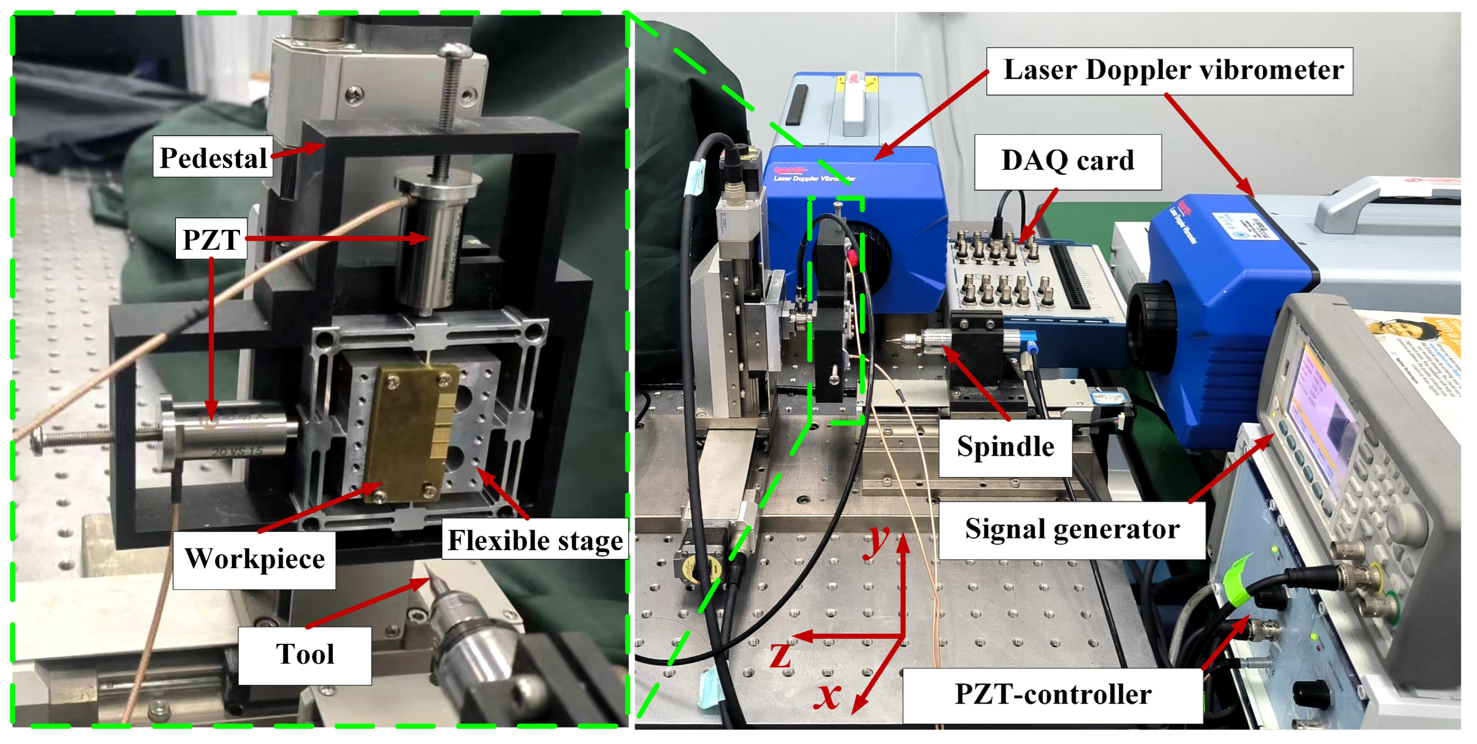
To verify the surface texture models proposed in Section 2, a series of test experiments were designed and carried out on a precision three-axis micro-milling machine. The micro-milling machine was developed in-house using KXL/KYL/KZL 06050 C1 g series motorized stages from Suruga Seiki Company. The flexible stages were monolithically fabricated from Al7075-T651 by micro milling and wire electrical discharge machining methods. By setting the frequency and amplitude of the piezoelectrical actuator, an elliptic trajectory could be provided by the flexible stage and transmitted to the workpiece [32]. The experimental setup shown in Figure 13 mainly includes the flexible stage, micro-milling machine, input DAQ card, signal generator, and laser Doppler vibrometer. The flexible stages were driven by the two cylindrical encapsulated piezoelectric actuators (CoreMorrow, PSt150/10/20 VS15), with the preload devices built in to ensure the preloading force was identical in the two vibration directions. The driving signals were generated by the signal generator (Agilent 33500B) and further amplified by the piezoelectric-control system (Coremorrow’s E01.A2). Meanwhile, two laser Doppler vibrometers were fixed on the feed and vertical directions to monitor the flexible stage’s real-time output displacements. The displacement data were collected by the DAQ card (NI 9221) and sent to the LABVIEW 2016 software for analysis. The surface morphologies of the milling results were characterized by using an optical microscope (Leica DMi 8C) and a scanning electron microscope (SEM, ZEISS Sigma 300, Oberkochen, Germany).
The machining tests were carried out by using a 0.6 mm diameter uncoated two-flute micro end tool, while copper was chosen as the workpiece material for the convenience of observation. The experiment parameters are listed in Table 5. According to Equation (6), the parameters of tests 2 and 4 were within the condition of wave-type texture, while tests 3 and 5 were within the condition of fish-type texture. The cutting depth was all set as 50 μm.

4.2. Results and Discussion

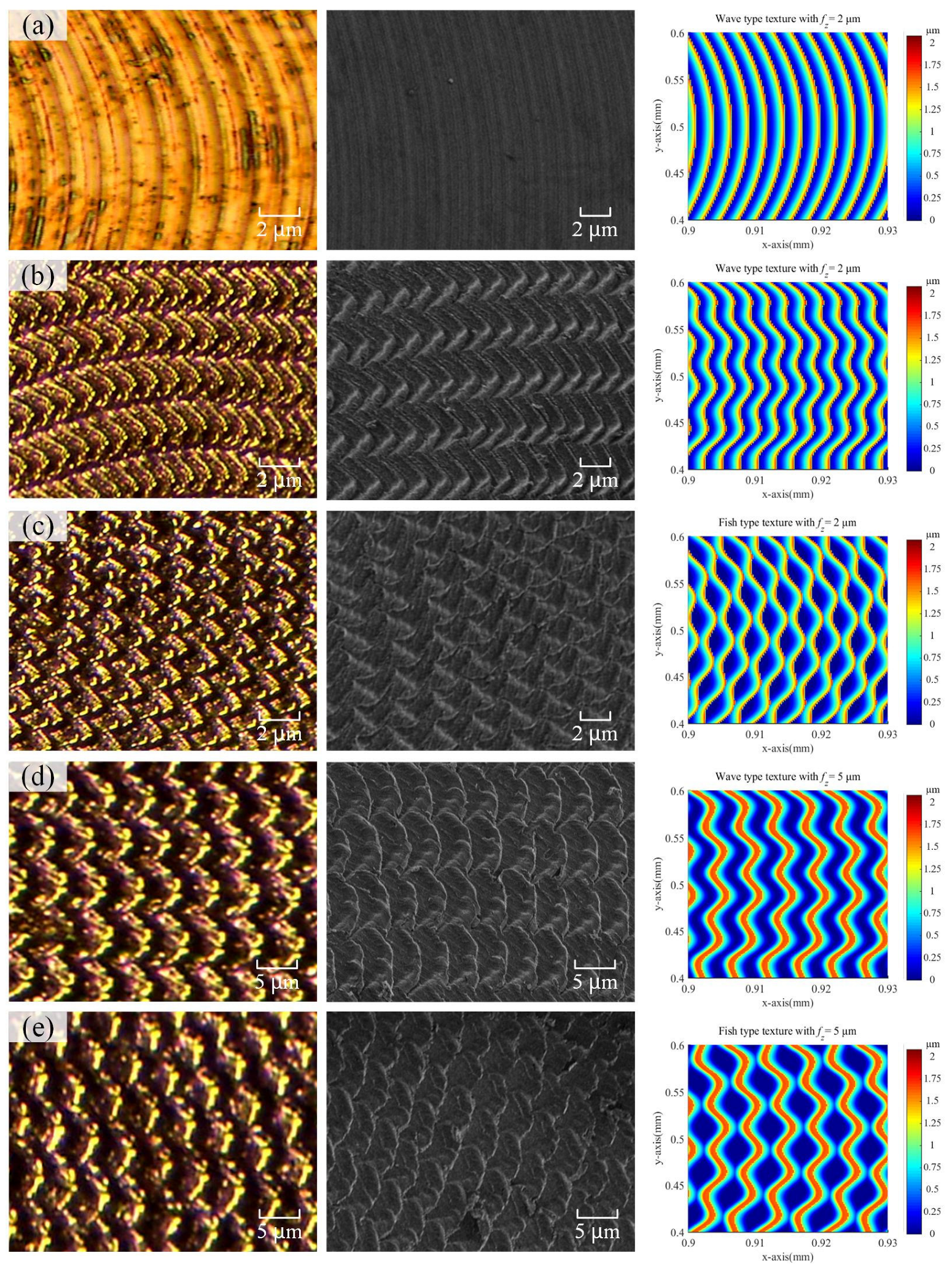
Figure 14 shows the comparison between the machined surface textures and simulated textures, where the experimental results were observed by an optical microscope and a scanning electron microscope. Figure 14a shows the surface generated by the micro milling without vibration assistance, in which the circular tool marks are presented regularly. Figure 14b–e illustrates the surface texture of the surface machined by the vibration-assisted micro milling. Compared to the machining results of test 1, the surface texture shows a significant difference. Among them, the results of tests 2 and 4 in Figure 14b,d generated the wave-type texture, in which the peaks (valleys) of one tooth correspond to the peaks (valleys) of another tooth. The fish-type texture could be observed in the results of tests 3 and 5, as shown in Figure 14c,e. The peaks (valleys) of one tooth adjoin with the valleys (peaks) of another tooth precisely, as predicted in the simulated textures. The results show that vibration-assisted micro milling could be utilized as a new controllable and efficient method to generate certain surface textures.
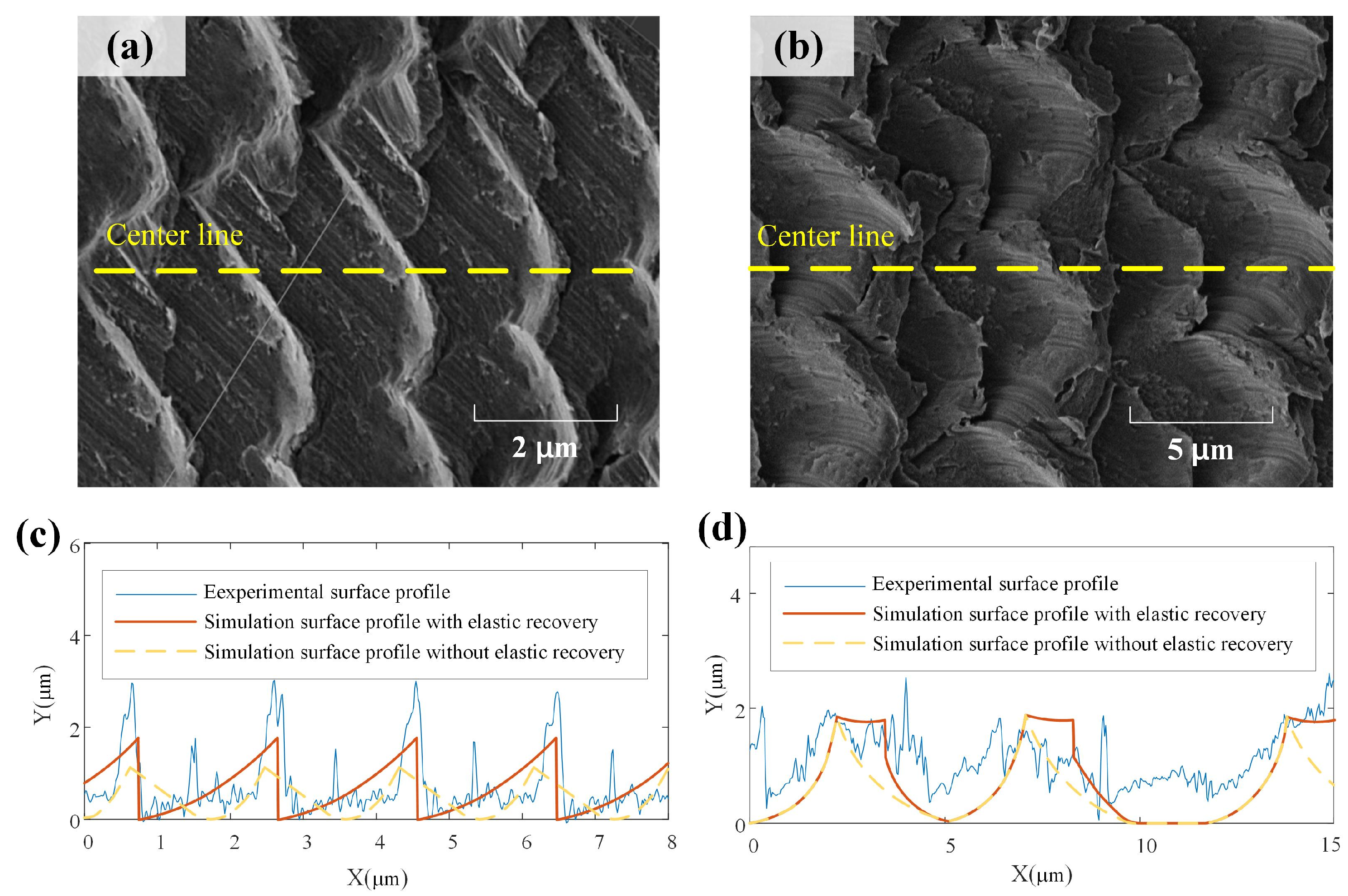
The partially enlarged images of machined surfaces corresponding to test 2 and test 5 shown in Figure 15a,b were used to further study the influence of feed per tooth. The milling surface with a feed per tooth of 5 μm/tooth in test 5 exhibits a thick and wide texture compared to the result of test 2. In terms of size and geometry, the experimental results consistently align with the simulation results depicted in Figure 8. For a quantitative comparison, the surface profiles of the center line measured from the SEM images are shown in Figure 15c,d, together with the simulated surface profiles considering the elastic recovery using the proposed approach and the simulated surface profiles without considering the elastic recovery by utilizing the method from other references [27,28]. It is evident that the simulated surface profile considering elastic recovery exhibits significant consistency with the experimental results when compared with the simulation results without elastic recovery. This verifies the model’s capability to predict absolute dimensions. This supports the assertion that the vibration-assisted micro-milling technique is a flexible and efficient method for texturing, applicable to fabricating microfluidic devices, MEMS components, and engineered surfaces with customized optical, tribological, and biological properties.
However, some subtle differences can be observed between the simulated and experimental surface profiles, which can be attributed to effects like tool wear, tool run-out and deflection, and plastic side flow, which are not included in the current model. In future work, the model can be further developed by incorporating more comprehensive tool-work interactions. Potential model refinements will be performed, including simulating variable chip thickness and runout effects for improved morphology prediction.

5. Conclusions

In this paper, a novel model was developed to predict the 3D surface textures in vibration-assisted micro milling by considering significant micro cutting factors. The simulation assessment and experimental verification demonstrated the capability for flexible and accurate texturing. The following key conclusions can be drawn:
  • A precise analytical approach was proposed to model the surface generation process in vibration-assisted micro milling. This model incorporates critical size effects, including tool edge geometry, minimum chip thickness, and material elastic recovery, which enables reliable prediction of absolute texture dimensions.
  • The modeling approach provides insights into texture formation mechanisms under various machining condition parameters. By controlling the spindle speed and vibration frequency, predictable wave-type and fish scale-type morphologies can be generated, as evidenced by both simulation and experiments.
  • A 2-DOF flexible vibration stage was designed and fabricated. The micro-milling experiments demonstrated the feasibility of embedding controlled micro-scale surface patterns onto machined workpieces using this vibration-assisted method. Reasonable consistency was achieved between simulated and experimentally fabricated textures.

Author Contributions

All authors have contributed to the research and realization of this paper. B.S. and Y.R.; formal analysis, investigation, validation, and writing—original draft preparation, D.Z.; supervision, X.J.; Conceptualization, Y.C. and H.L.; methodology, writing—review and editing. All authors have read and agreed to the published version of the manuscript.

Funding

This research is supported by Program of Ministry of Industry and Information Technology (No. 2023ZY01082), and Program of Tianjin Science and Technology (No. 21ZXJBGX00020).

Data Availability Statement

Data are contained within the article.

Conflicts of Interest

The authors declare no conflicts of interest.

Appendix A

Table A1. Calculation results of different parameter groups.
Ordert1t2r2CfQ
10.50.50.50.3521 1421 4.77 × 10⁻²
20.50.510.3598 1405 5.01 × 10⁻²
30.50.51.50.3111 1511 3.60 × 10⁻²
40.510.50.0871 2857 1.10 × 10⁻³
50.5110.0957 2725 1.55 × 10⁻³
60.511.50.0944 2744 1.48 × 10⁻³
70.51.50.50.0497 3783 1.48 × 10⁻⁵
80.51.510.0561 3557 8.01 × 10⁻⁵
90.51.51.50.0596 3453 1.40 × 10⁻⁴
1010.50.50.2126 1828 1.47 × 10⁻²
1110.510.2146 1820 1.50 × 10⁻²
1210.51.50.1918 1925 1.14 × 10⁻²
13110.50.0617 3394 1.83 × 10⁻⁴
141110.0662 3276 2.95 × 10⁻⁴
15111.50.0617 3393 1.84 × 10⁻⁴
1611.50.50.0324 4685 3.02 × 10⁻⁴
1711.510.0363 4425 1.50 × 10⁻⁴
1811.51.50.0371 4375 1.27 × 10⁻⁴
191.50.50.50.1119 2519 2.60 × 10⁻³
201.50.510.1123 2516 2.63 × 10⁻³
211.50.51.50.1050 2601 2.12 × 10⁻³
221.510.50.0455 3953 1.10 × 10⁻⁵
231.5110.0479 3853 9.03 × 10⁻⁶
241.511.50.0439 4023 1.87 × 10⁻⁵
251.51.50.50.0241 5431 9.76 × 10⁻⁴
261.51.510.0266 5170 7.02 × 10⁻⁴
271.51.51.50.0263 5194 7.25 × 10⁻⁴

References

  1. Maboudian, R.; Howe, R.T. Critical Review: Adhesion in Surface Micromechanical Structures. J. Vac. Sci. Technol. B 1997, 15, 1–20. [Google Scholar] [CrossRef]
  2. Jung, Y.C.; Bhushan, B. Contact Angle, Adhesion and Friction Properties of Micro-and Nanopatterned Polymers for Superhydrophobicity. Nanotechnology 2006, 17, 4970–4980. [Google Scholar] [CrossRef]
  3. Moskal, D.; Martan, J.; Honner, M. Scanning Strategies in Laser Surface Texturing: A Review. Micromachines 2023, 14, 1241. [Google Scholar] [CrossRef] [PubMed]
  4. Wu, Q.; Chen, G.; Liu, Q.; Pan, B.; Chen, W. Investigation on the Micro Cutting Mechanism and Surface Topography Generation in Ultraprecision Diamond Turning. Micromachines 2022, 13, 381. [Google Scholar] [CrossRef] [PubMed]
  5. Alpas, A.T.; Zhang, J. Effect of Microstructure (Particulate Size and Volume Fraction) and Counterface Material on the Sliding Wear Resistance of Particulate-Reinforced Aluminum Matrix Composites. Metall. Mater. Trans. A 1994, 25, 969–983. [Google Scholar] [CrossRef]
  6. Wang, Z.; Wu, L.; Fang, Y.; Dun, A.; Zhao, J.; Xu, X.; Zhu, X. Application of Flow Field Analysis in Ion Beam Figuring for Ultra-Smooth Machining of Monocrystalline Silicon Mirror. Micromachines 2022, 13, 318. [Google Scholar] [CrossRef] [PubMed]
  7. Derevyanko, D.I.; Shelkovnikov, V.V.; Orlova, N.A.; Goldenberg, B.G.; Lemzyakov, A.G.; Korolkov, V.P. Fabrication of High-Aspect-Ratio Microstructures for LIGA-Technology by Sinchrotron Radiation Polymerisation of Thetetraacrylate Monomer. Phys. Procedia 2017, 86, 122–126. [Google Scholar] [CrossRef]
  8. Takahata, K.; Gianchandani, Y.B. Batch Mode Micro-Electro-Discharge Machining. J. Microelectromech. Syst. 2002, 11, 102–110. [Google Scholar] [CrossRef]
  9. Scott, S.M.; Ali, Z. Fabrication Methods for Microfluidic Devices: An Overview. Micromachines 2021, 12, 319. [Google Scholar] [CrossRef]
  10. Axinte, D.; Huang, H.; Yan, J.; Liao, Z. What Micro-Mechanical Testing Can Reveal about Machining Processes. Int. J. Mach. Tools Manuf. 2022, 183, 103964. [Google Scholar] [CrossRef]
  11. Song, B.; Jing, X.; Yang, H.; Zheng, S.; Zhang, D.; Li, H. On Unsteady-Cutting State Material Separation and Dead Metal Zone Modeling Considering Chip Fracture. J. Manuf. Process 2023, 108, 62–78. [Google Scholar] [CrossRef]
  12. Zheng, L.; Chen, W.; Huo, D. Review of Vibration Devices for Vibration-Assisted Machining. Int. J. Adv. Manuf. Technol. 2020, 108, 1631–1651. [Google Scholar] [CrossRef]
  13. Yang, Z.; Zhu, L.; Zhang, G.; Ni, C.; Lin, B. Review of Ultrasonic Vibration-Assisted Machining in Advanced Materials. Int. J. Mach. Tools Manuf. 2020, 156, 103594. [Google Scholar] [CrossRef]
  14. Yang, Z.; Zou, P.; Zhou, L.; Wang, X.; Usman, M.M. Modeling and Experimental Analysis of Surface Topography Generation Mechanism during Ultrasonic Vibration-Assisted Grinding. Precis. Eng. 2023, 80, 30–44. [Google Scholar] [CrossRef]
  15. Feng, Y.; Hsu, F.C.; Lu, Y.T.; Lin, Y.F.; Lin, C.T.; Lin, C.F.; Lu, Y.C.; Liang, S.Y. Force Prediction in Ultrasonic Vibration-Assisted Milling. Mach. Sci. Technol. 2020, 25, 307–330. [Google Scholar] [CrossRef]
  16. Zhu, W.L.; Zhu, Z.; He, Y.; Ehmann, K.F.; Ju, B.F.; Li, S. Development of a Novel 2-D Vibration-Assisted Compliant Cutting System for Surface Texturing. IEEE-ASME Trans. Mechatron. 2017, 22, 1796–1806. [Google Scholar] [CrossRef]
  17. Yuan, Y.; Zhang, D.; Zhu, H.; Ehmann, K.F. Machining of Micro Grayscale Images on Freeform Surfaces by Vibration-Assisted Cutting. J. Manuf. Process 2020, 58, 660–667. [Google Scholar] [CrossRef]
  18. Jin, X.; Xie, B. Experimental Study on Surface Generation in Vibration-Assisted Micro-Milling of Glass. Int. J. Adv. Manuf. Technol. 2015, 81, 507–512. [Google Scholar] [CrossRef]
  19. Zhang, Z.; Liu, W.; Chen, X.; Zhang, Y.; Xu, C.; Wang, K.; Wang, W.; Jiang, X. Generation Mechanism of Surface Micro-Texture in Axial Ultrasonic Vibration-Assisted Milling (AUVAM). Int. J. Adv. Manuf. Technol. 2022, 122, 1651–1667. [Google Scholar] [CrossRef]
  20. Chen, W.; Huo, D.; Shi, Y.; Hale, J.M. State-of-the-Art Review on Vibration-Assisted Milling: Principle, System Design, and Application. Int. J. Adv. Manuf. Technol. 2018, 97, 2033–2049. [Google Scholar] [CrossRef]
  21. Zheng, L.; Chen, W.; Huo, D. Investigation on the Tool Wear Suppression Mechanism in Non-Resonant Vibration-Assisted Micro Milling. Micromachines 2020, 11, 380. [Google Scholar] [CrossRef]
  22. Zheng, L.; Fang, M.; Chen, W.; Huo, D.; Li, H. Enhancement Mechanism of Fish-Scale Surface Texture on Flow Switching and Mixing Efficiency in Microfluidic Chips. Langmuir 2023, 39, 7396–7407. [Google Scholar] [CrossRef] [PubMed]
  23. Yang, L.; Zhibing, L.; Xibin, W.; Tao, H. Experimental Study on Cutting Force and Surface Quality in Ultrasonic Vibration-Assisted Milling of C/SiC Composites. Int. J. Adv. Manuf. Technol. 2021, 112, 2003–2014. [Google Scholar] [CrossRef]
  24. Zheng, L.; Chen, W.; Huo, D.; Lyu, X. Design, Analysis, and Control of a Two-Dimensional Vibration Device for Vibration-Assisted Micromilling. IEEE-ASME Trans. Mechatron. 2020, 25, 1510–1518. [Google Scholar] [CrossRef]
  25. Börner, R.; Winkler, S.; Junge, T.; Titsch, C.; Schubert, A.; Drossel, W.G. Generation of Functional Surfaces by Using a Simulation Tool for Surface Prediction and Micro Structuring of Cold-Working Steel with Ultrasonic Vibration Assisted Face Milling. J. Mater. Process Technol. 2018, 255, 749–759. [Google Scholar] [CrossRef]
  26. Ding, H.; Chen, S.J.; Ibrahim, R.; Cheng, K. Investigation of the Size Effect on Burr Formation in Two-Dimensional Vibration-Assisted Micro End Milling. Proc. Inst. Mech. Eng. Part B-J. Eng. Manuf. 2011, 225, 2032–2039. [Google Scholar] [CrossRef]
  27. Chen, W.; Zheng, L.; Huo, D.; Chen, Y. Surface Texture Formation by Non-Resonant Vibration Assisted Micro Milling. J. Micromech. Microeng. 2018, 28, 025006. [Google Scholar] [CrossRef]
  28. Zheng, L.; Chen, W.; Pozzi, M.; Teng, X.; Huo, D. Modulation of Surface Wettability by Vibration Assisted Milling. Precis. Eng. 2019, 55, 179–188. [Google Scholar] [CrossRef]
  29. Lv, B.; Lin, B.; Cao, Z.; Liu, W.; Wang, G. Numerical Simulation and Experimental Investigation of Structured Surface Generated by 3D Vibration-Assisted Milling. J. Manuf. Process 2023, 89, 371–383. [Google Scholar] [CrossRef]
  30. Yuan, Y.; Yu, K.; Zhang, C.; Chen, Q.; Yang, W. Generation of Textured Surfaces by Vibration-Assisted Ball-End Milling. Nanomanuf. Metrol. 2023, 6, 19. [Google Scholar] [CrossRef]
  31. Jing, X.; Song, B.; Xu, J.; Zhang, D. Mathematical Modeling and Experimental Verification of Surface Roughness in Micro-End-Milling. Int. J. Adv. Manuf. Technol. 2022, 120, 7627–7637. [Google Scholar] [CrossRef]
  32. Song, B.; Jing, X.; Ren, Y.; Ren, Y.; Li, H. Design and Experimentation of a Novel Separable Vibration-Assisted Stage. Nanomanuf. Metrol. 2023, 6, 23. [Google Scholar] [CrossRef]
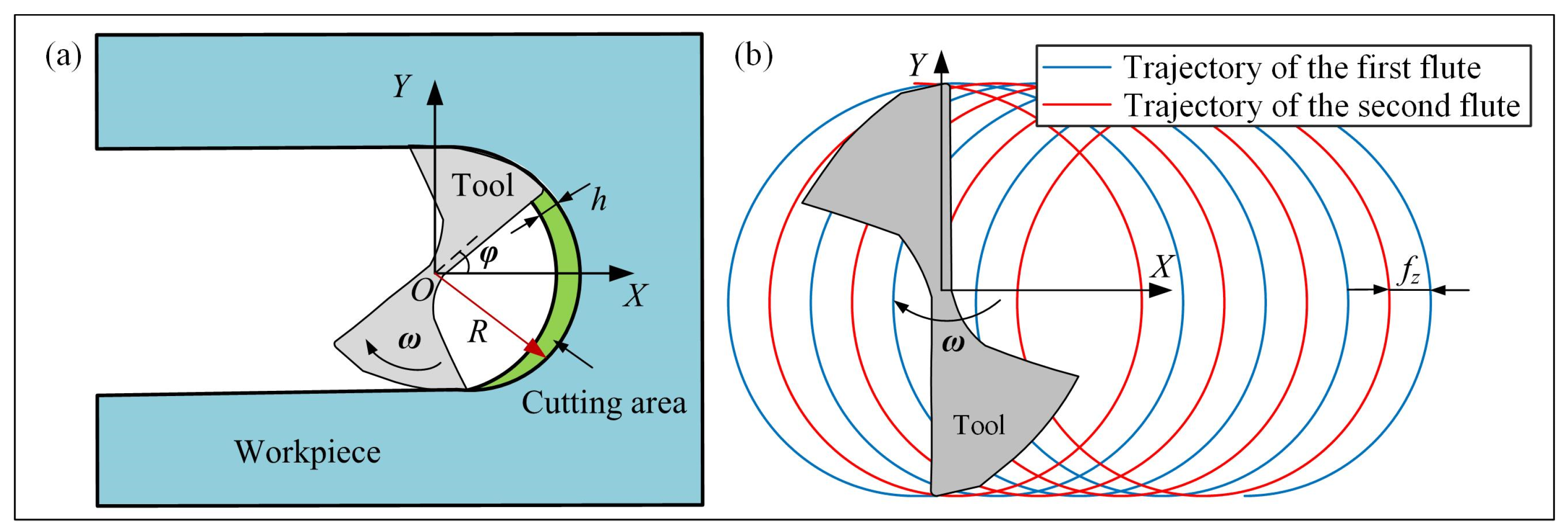
Figure 1. Micro-milling model: (a) micro end-milling operation, (b) tool trajectory.
Micromachines 15 00139 g001
Figure 2. Micro-milling profile modeling: (a) the tooltip trajectory along the centerline, (b) machined surface profile along the centerline.
Micromachines 15 00139 g002
Figure 3. A 2D surface profile under different feeds per tooth (a) without considering elastic recovery, (b) considering elastic recovery.
Micromachines 15 00139 g003
Figure 4. Three-dimensional surface profile modeling.
Micromachines 15 00139 g004
Figure 5. A 3D surface profile under different feeds per tooth (a) fz = 2 μm, (b) fz = 5 μm.
Micromachines 15 00139 g005
Figure 6. Two typical surface morphologies (a) wave-type trajectory, (b) fish-type tool trajectory.
Micromachines 15 00139 g006
Figure 7. Flowchart to calculate the 3D surface texture.
Micromachines 15 00139 g007
Figure 8. 3D surface texture with vibration-assisted under different feed per tooth (a) surface texture with fz = 2 μm/tooth (b) surface texture with fz = 5 μm/tooth.
Micromachines 15 00139 g008
Figure 9. Mechanical design: (a) vibration-assisted stage, (b) flexible stage.
Micromachines 15 00139 g009
Figure 10. Influence of three parameters t2, t1, r2 on (a) compliance, (b) natural frequency.
Micromachines 15 00139 g010
Figure 11. Contour of three parameters t2, t1, r2 on (a) compliance, (b) resonant frequency.
Micromachines 15 00139 g011
Figure 12. Finite simulation results: (a) static simulation, (b) stress distribution, (c) dynamic simulation.
Micromachines 15 00139 g012
Figure 13. Experiment setup.
Micromachines 15 00139 g013
Figure 14. Machined surface textures observed by optical microscope and scanning electron microscope with conditions of test 1: (a); test 2: (b); test 3: (c); test 4: (d); test 5: (e).
Micromachines 15 00139 g014
Figure 15. Partially enlarged surface profile: (a) surface profile of test 2, (b) surface profile of test 5, (c) center line profile of test 2, (d) center line profile of test 5.
Micromachines 15 00139 g015
Table 1. Milling condition and cutting parameters.
Tool Radius (μm)Spindle Speed
(rpm)
Tool Edge Radius (μm)MUCT (μm)Material Elastic Recovery Ratio
600500052.40.2
Table 2. Simulation conditions.
NoSpindle Speed
(rpm)
Vibration
Frequency (Hz)
Vibration
Amplitude (µm)
Phase DifferenceFeed Per Tooth
(µm)
Test a500024172902
Test b500025002902
Table 3. Key parameters of the structure.
ParametersL1L2bs1s2
Value (mm)4171087
Table 4. Mechanical properties of Al7075-T651.
MaterialDensityYoung’s ModulusPoisson’s RatioYield StrengthTensile Strength
Al7075-T6512.81 g/cm371 GPa0.33455 MPa524 MPa
Table 5. Experiment parameters.
NoSpindle Speed
(rpm)
Vibration
Frequency (Hz)
Vibration
Amplitude (µm)
Feed Per Tooth
(µm)
Test 15000002
Test 25000250022
Test 35000241722
Test 45000250025
Test 55000241725
Disclaimer/Publisher’s Note: The statements, opinions and data contained in all publications are solely those of the individual author(s) and contributor(s) and not of MDPI and/or the editor(s). MDPI and/or the editor(s) disclaim responsibility for any injury to people or property resulting from any ideas, methods, instructions or products referred to in the content.