
Photonic Generation of Arbitrary Microwave Waveforms with Anti-Dispersion Transmission Capability


 ,
, 
Abstract
1. Introduction
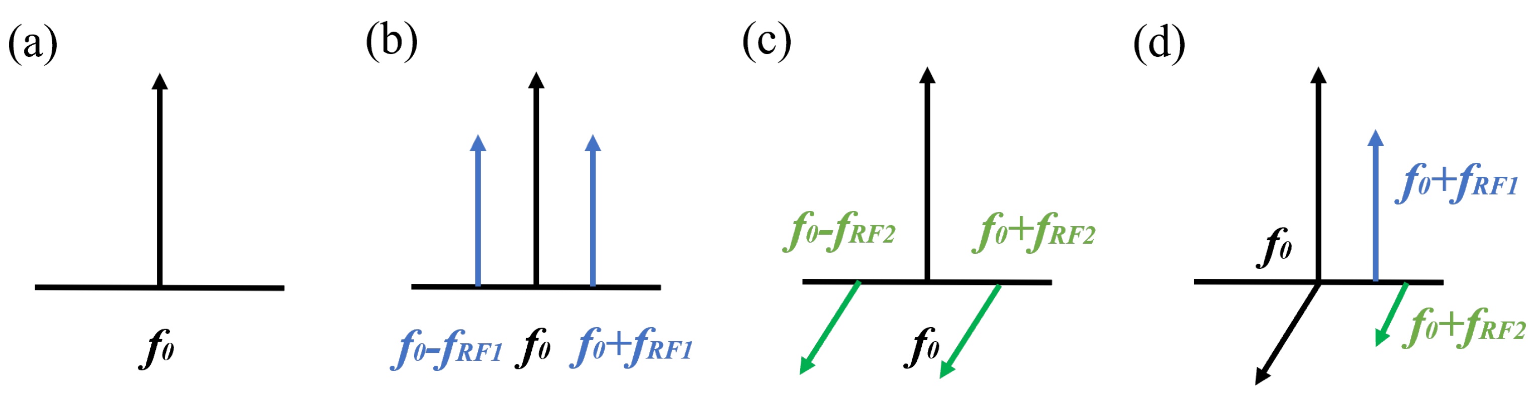
2. Principle
3. Experiment and Results
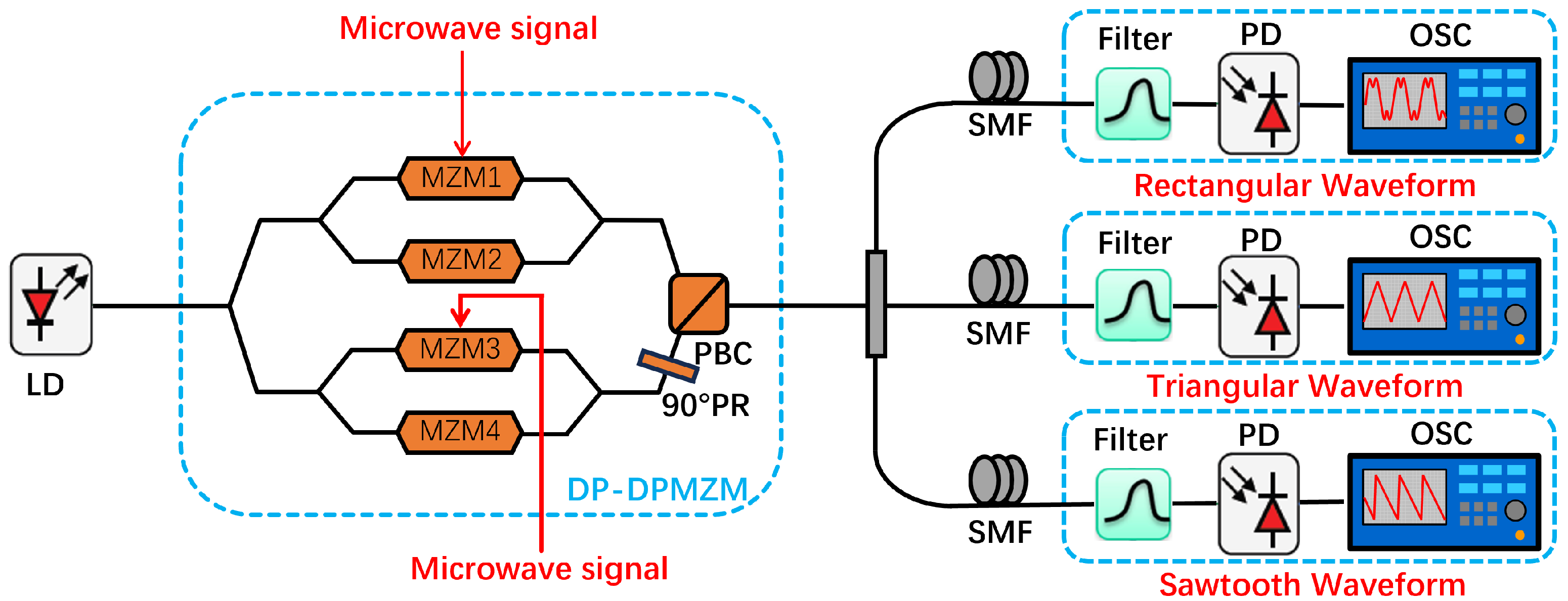
3.1. Experimental Setup
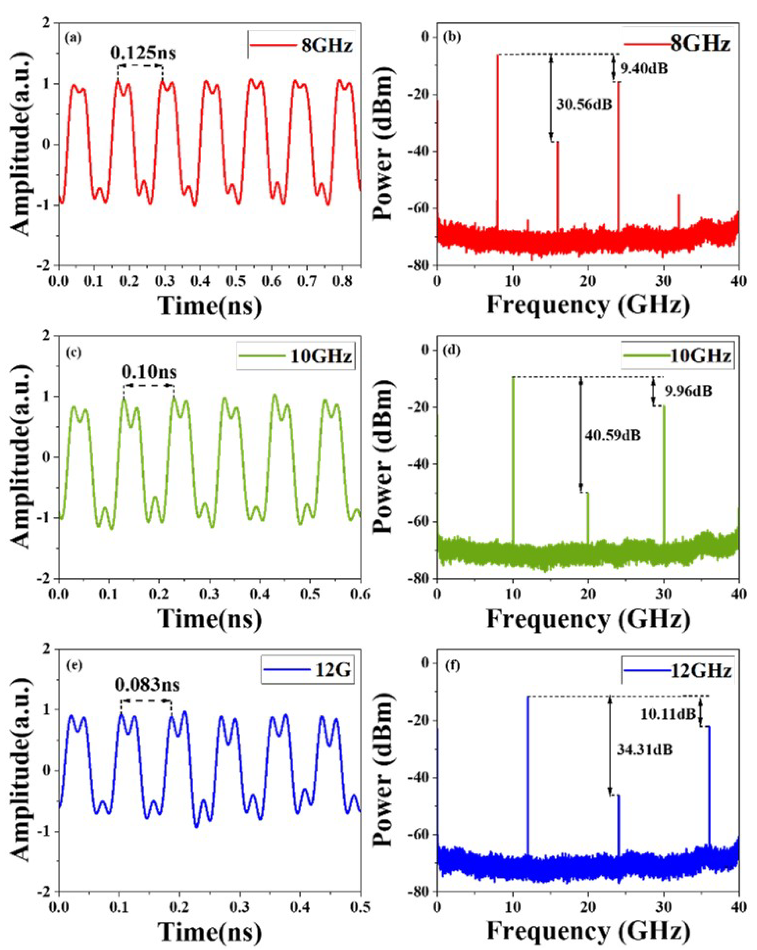
3.2. Waveform Generation
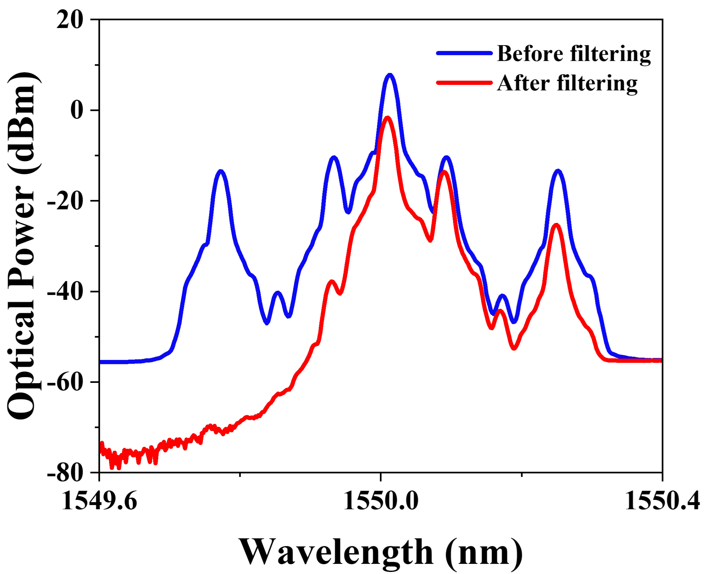
3.3. Anti-Dispersion Transmission
4. Conclusions
Author Contributions
Funding
Data Availability Statement
Conflicts of Interest
References
- Rihaczek, A.W. Principles of High-Resolution Radar; Artech House: Norwood, MA, USA, 1996; pp. 184–185. [Google Scholar]
- Yao, J.P. Photonic generation of microwave arbitrary waveforms. Opt. Commun. 2011, 284, 3723–3736. [Google Scholar] [CrossRef]
- Cundiff, S.T.; Weiner, A.M. Optical arbitrary waveform generation. Nat. Photon. 2010, 4, 760–766. [Google Scholar] [CrossRef]
- Parmigiani, F.; Ibsen, M.; Ng, T.T.; Provost, L.; Petropoulos, P.; Richardson, D.J. An efficient wavelength converter exploiting a grating-based saw-tooth pulse shaper. IEEE Photon. Technol. Lett. 2008, 20, 1461–1463. [Google Scholar] [CrossRef]
- Jiang, Z.; Huang, C.B.; Leaird, D.E.; Weiner, A.M. Optical arbitrary waveform processing of more than 100 spectral comb lines. Nat. Photon. 2007, 1, 463–467. [Google Scholar] [CrossRef]
- Latkin, A.I.; Boscolo, S.; Bhamber, R.S.; Turitsyn, S.K. Optical frequency conversion, pulse compression and signal copying using triangular pulses. In Proceedings of the 2008 34th European Conference on Optical Communication, Brussels, Belgium, 21–25 September 2008. [Google Scholar]
- Latkin, A.I.; Boscolo, S.; Bhamber, R.S.; Turitsyn, S.K. Doubling of optical signals using triangular pulses. J. Opt. Soc. Amer. B 2009, 26, 1492–1496. [Google Scholar] [CrossRef]
- Bhamber, R.S.; Latkin, A.I.; Boscolo, S.; Turitsyn, S.K. All-optical TDM to WDM signal conversion and partial regeneration using XPM with triangular pulses. In Proceedings of the 2008 34th European Conference on Optical Communication, Brussels, Belgium, 21–25 September 2008. [Google Scholar]
- Huang, C.B.; Leaird, D.E.; Weiner, A.M. Time-multiplexed photonically enabled radio-frequency arbitrary waveform generation with 100 ps transitions. Opt. Lett. 2007, 32, 3242–3244. [Google Scholar] [CrossRef] [PubMed]
- Ye, J.; Yan, L.; Pan, W.; Luo, B.; Zou, X.; Yi, A.; Yao, S. Photonic generation of triangular shaped pulses based on frequency-to-time conversion. Opt. Lett. 2011, 36, 1458–1460. [Google Scholar] [CrossRef] [PubMed]
- Li, W.; Wang, W.T.; Zhu, N.H. Photonic generation of radiofrequency waveforms based on dual-parallel Mach–Zehnder modulator. IEEE Photon. J. 2014, 6, 1–8. [Google Scholar]
- Li, J.; Zhang, X.; Hraimel, B.; Ning, T.; Pei, L.; Wu, K. Performance analysis of a photonic-assisted periodic triangular-shaped pulses generator. J. Lightw. Technol. 2012, 30, 1617–1624. [Google Scholar] [CrossRef]
- Chen, X.; Li, G.; Shi, D.; Wang, L.; Du, J.; Li, M.; Zhu, N.; Li, W. Photonic generation of rectangular and triangular microwave waveforms with Tunable Duty Cycle. Opt.Commun. 2022, 34, 371–374. [Google Scholar] [CrossRef]
- Liu, X.; Pan, W.; Zou, X.; Zheng, D.; Yan, L.; Luo, B.; Lu, B. Photonic generation of triangular-shaped microwave pulses using SBS-based optical carrier processing. J. Lightw. Technol. 2014, 32, 3797–3802. [Google Scholar] [CrossRef]
- He, Y.; Jiang, Y.; Zi, Y.; Bai, G.; Tian, J.; Xia, Y.; Zhang, X.; Dong, R.; Luo, H. Photonic microwave waveforms generation based on two cascaded single-drive Mach—Zehnder modulators. Opt. Express. 2018, 26, 7829–7841. [Google Scholar] [CrossRef] [PubMed]
- Liu, W.; Yao, J. Photonic generation of microwave waveforms based on a polarization modulator in a Sagnac loop. J. Lightw. Technol. 2014, 32, 3637–3644. [Google Scholar] [CrossRef]


Disclaimer/Publisher’s Note: The statements, opinions and data contained in all publications are solely those of the individual author(s) and contributor(s) and not of MDPI and/or the editor(s). MDPI and/or the editor(s) disclaim responsibility for any injury to people or property resulting from any ideas, methods, instructions or products referred to in the content. |
© 2024 by the authors. Licensee MDPI, Basel, Switzerland. This article is an open access article distributed under the terms and conditions of the Creative Commons Attribution (CC BY) license (https://creativecommons.org/licenses/by/4.0/).
Share and Cite
Zhang, X.; Zhai, K.; Zhu, S.; Wen, H.; Liu, Y.; Zhu, N. Photonic Generation of Arbitrary Microwave Waveforms with Anti-Dispersion Transmission Capability. Micromachines 2024, 15, 1214. https://doi.org/10.3390/mi15101214
Zhang X, Zhai K, Zhu S, Wen H, Liu Y, Zhu N. Photonic Generation of Arbitrary Microwave Waveforms with Anti-Dispersion Transmission Capability. Micromachines. 2024; 15(10):1214. https://doi.org/10.3390/mi15101214
Chicago/Turabian StyleZhang, Xinyan, Kunpeng Zhai, Sha Zhu, Huashun Wen, Yu Liu, and Ninghua Zhu. 2024. "Photonic Generation of Arbitrary Microwave Waveforms with Anti-Dispersion Transmission Capability" Micromachines 15, no. 10: 1214. https://doi.org/10.3390/mi15101214
APA StyleZhang, X., Zhai, K., Zhu, S., Wen, H., Liu, Y., & Zhu, N. (2024). Photonic Generation of Arbitrary Microwave Waveforms with Anti-Dispersion Transmission Capability. Micromachines, 15(10), 1214. https://doi.org/10.3390/mi15101214