
Control of Self-Winding Microrobot Using an Electromagnetic Drive System: Integration of Movable Electromagnetic Coil and Permanent Magnet


Abstract
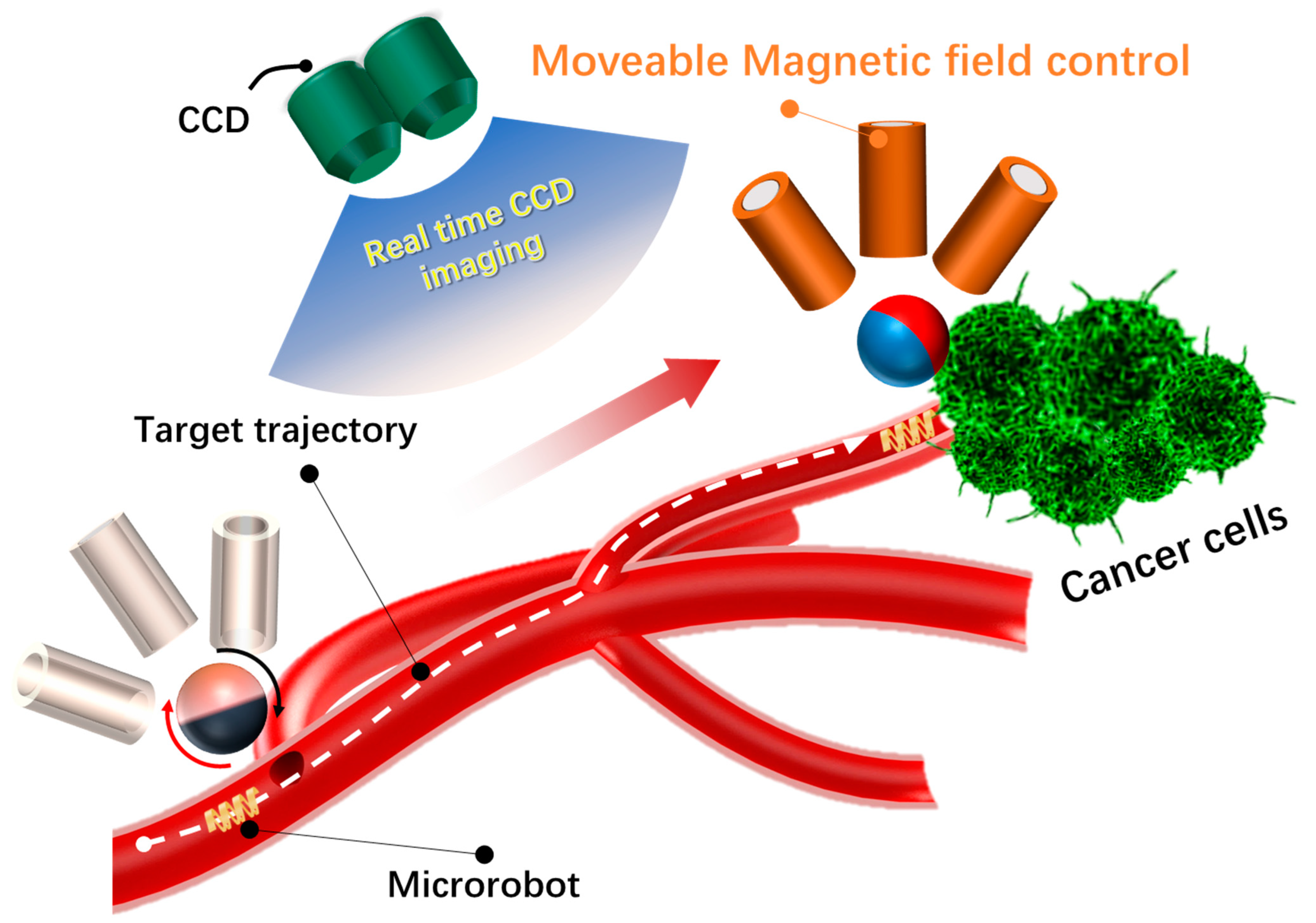
:1. Introduction
2. Materials and Methods
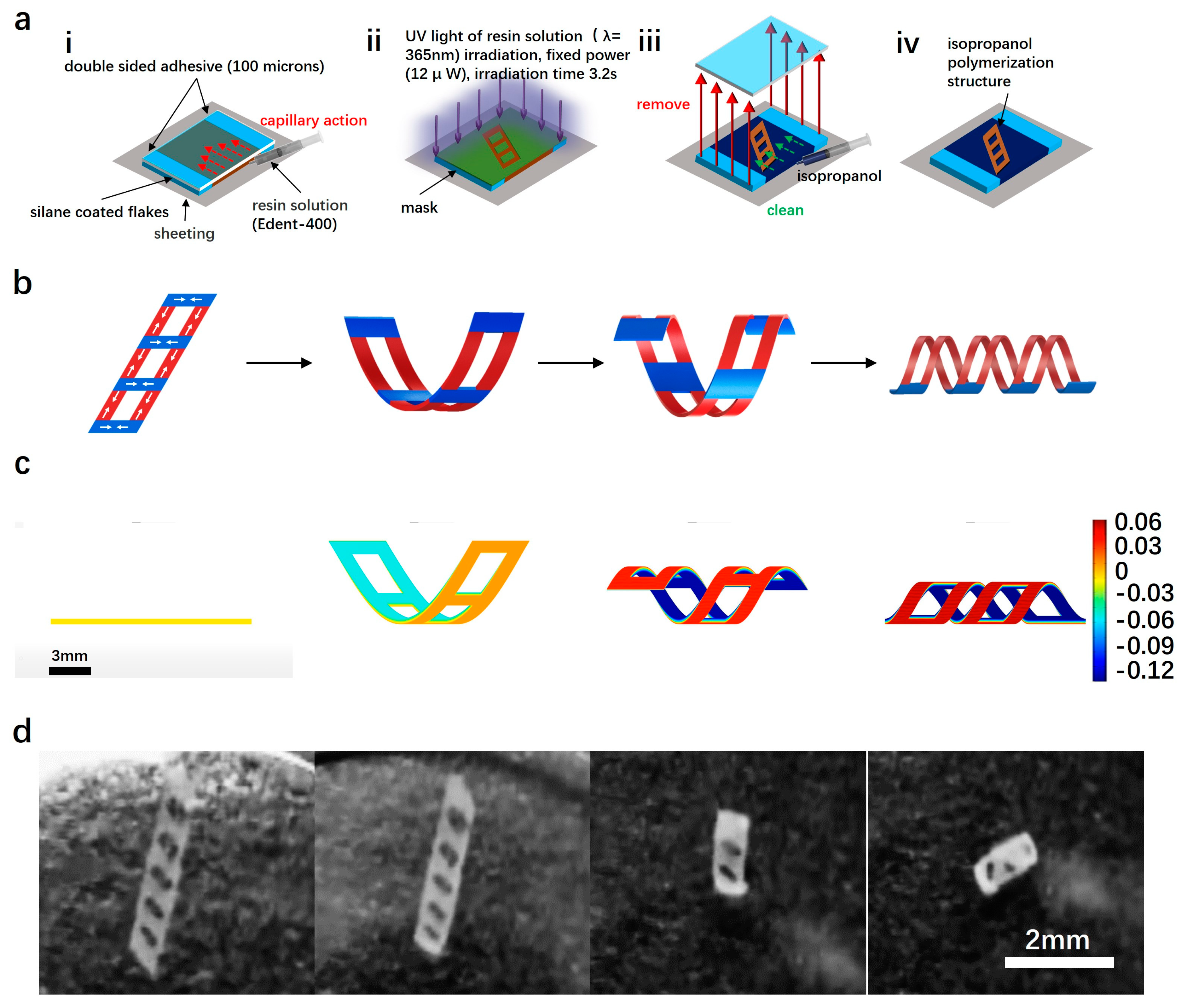
2.1. Magnetic Microrobot
- (i)
- Two transparent slides, each with areas of 24 × 24 mm and 20 × 20 mm, were prepared. Double-sided tape (thickness: 100 μm; Nitto, Inc., Osaka, Japan) was then applied between them to create the microchamber.
- (ii)
- For the biocompatible resin solution, a mixture of 50 wt% of e-dent 400 resin and 50 wt% NdFeB particles was prepared using a plenary mixer at 2000 rpm for 30 min.
- (iii)
- The resin solution was injected into the chamber via capillary force using a syringe. The microchamber was placed in the sample holder and cured with UV light (λ = 365 nm) for 6 s.
- (iv)
- The exposed sample was immersed in a Petri dish filled with isopropyl alcohol (IPA) and covered with aluminum foil for 2 h. Subsequently, the slide glass and tape were removed and rinsed with additional IPA to remove any un-polymerized ink. The patterned membranes adhered to the cover glass. Finally, after several minutes, the patterned membranes self-detached and rolled according to the initial design. (Figure 2d).
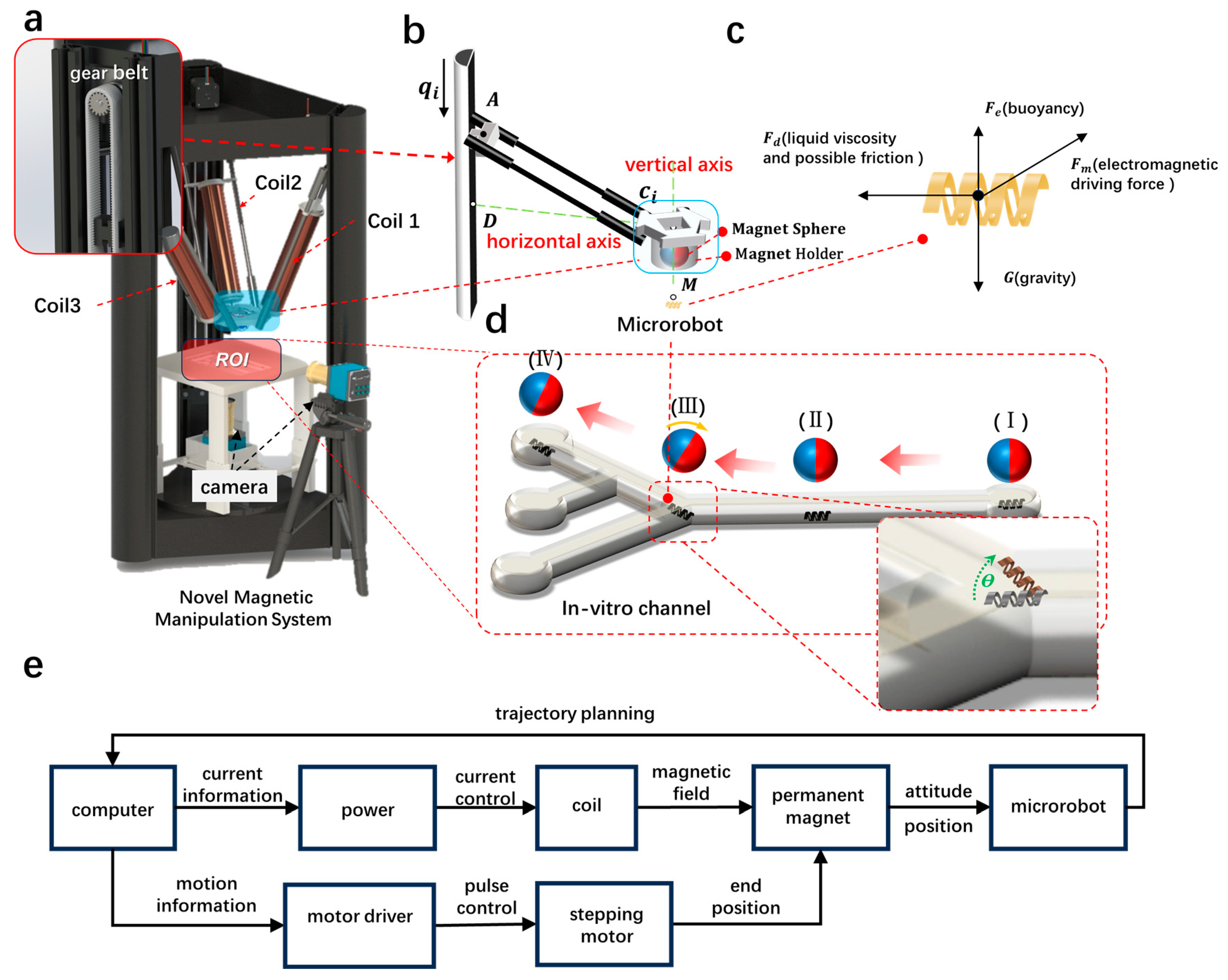
2.2. Electromagnetic Drive System
2.2.1. Electromagnetic Drive System Design
2.2.2. The Kinematic Analysis of Electromagnetic Drive Systems
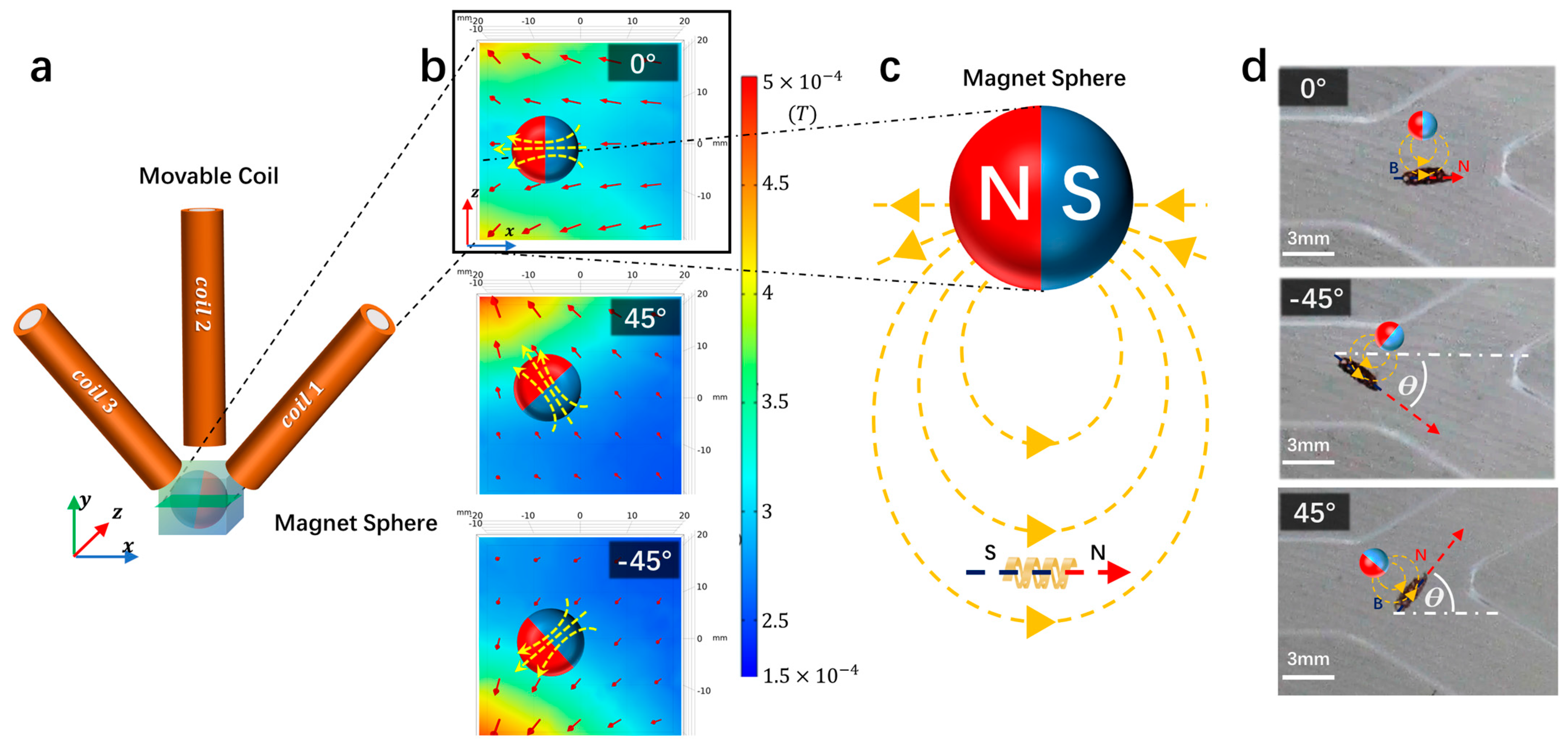
2.2.3. Control of Magnetic Sphere Direction in the Electromagnetic Drive System
2.2.4. Force Analysis of Magnetic Microrobot in Electromagnetic Drive Systems
- 1.
- Liquid Viscosity
- 2.
- Fm magnetic drive
- 3.
- G is gravity and Fb is buoyancy and possibly friction
3. Results
3.1. Microrobot Attitude Control
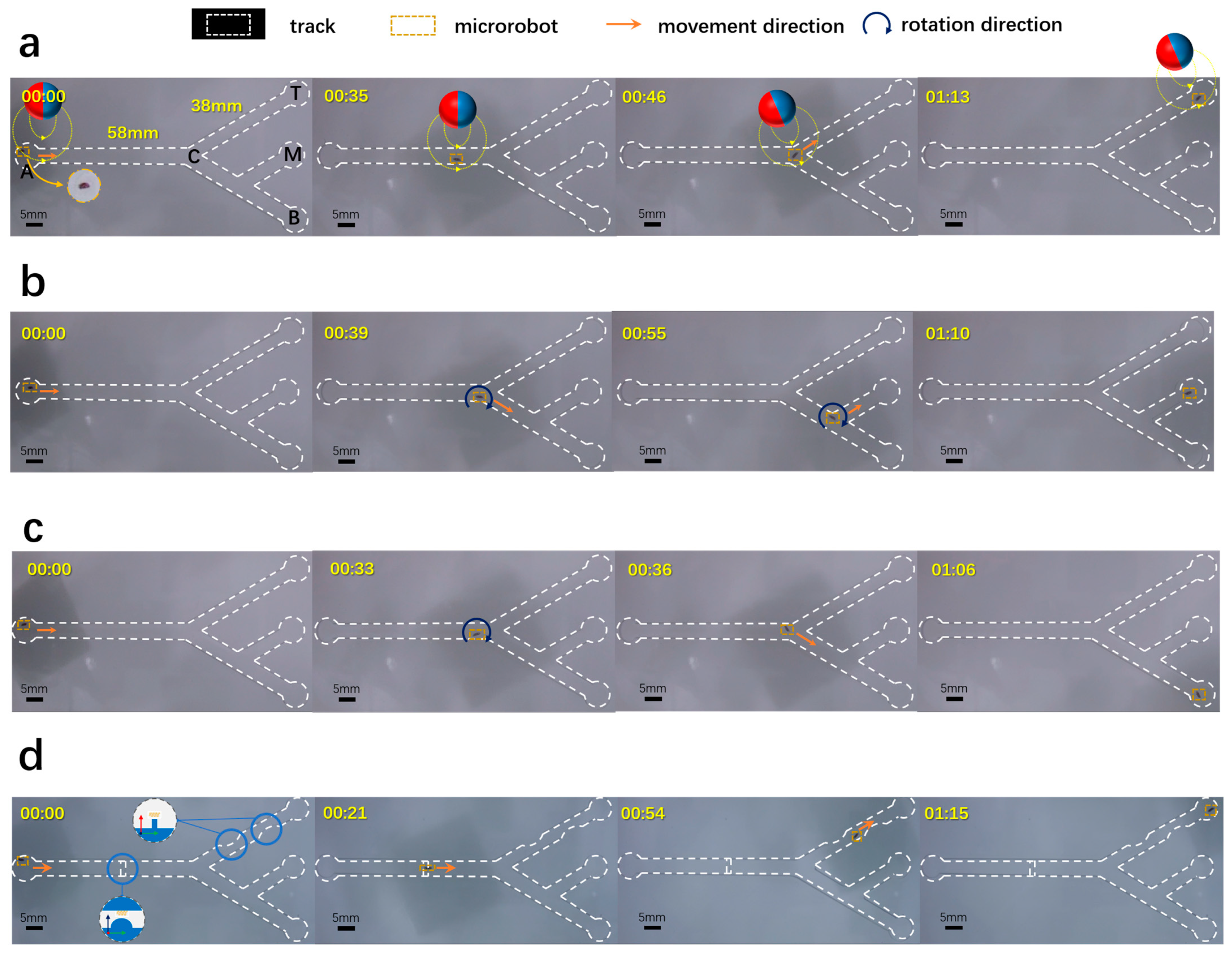
3.2. Microrobot 2D Targeting Experiments
3.3. Microrobot Three-Dimensional Targeting Experiments
4. Discussion and Conclusions
Supplementary Materials
Author Contributions
Funding
Data Availability Statement
Acknowledgments
Conflicts of Interest
References
- Ceylan, H.; Giltinan, J.; Kozielski, K. Mobile microrobots for bioengineering applications. Lab A Chip 2017, 17, 1705–1724. [Google Scholar] [CrossRef]
- Dabbagh, S.R.; Alseed, M.M.; Saadat, M. Biomedical Applications of Magnetic Levitation. Adv. NanoBiomed Res. 2021, 2, 2100103. [Google Scholar] [CrossRef]
- Phillips, J.W.; Prominski, A.; Tian, B. Recent advances in materials and applications for bioelectronic and biorobotic systems. View 2022, 3, 20200157. [Google Scholar] [CrossRef]
- Wang, M.; Wu, T.; Liu, R. Selective and Independent Control of Microrobots in a Magnetic Field: A Review. Engineering 2023, 24, 21–38. [Google Scholar] [CrossRef]
- Lin, D.; Wang, J.; Jiao, N. A Flexible Magnetically Controlled Continuum Robot Steering in the Enlarged Effective Workspace with Constraints for Retrograde Intrarenal Surgery. Adv. Intell. Syst. 2021, 3, 2000211. [Google Scholar] [CrossRef]
- Kummer, M.P.; Abbott, J.J.; Kratochvil, B.E. OctoMag: An electromagnetic system for 5-DOF wireless micromanipulation. IEEE Trans. Robot. 2010, 26, 1006–1017. [Google Scholar] [CrossRef]
- Hwang, G.; Ivan, I.A.; Agnus, J. Mobile microrobotic manipulator in microfluidics. Sens. Actuators A Phys. 2014, 215, 56–64. [Google Scholar] [CrossRef]
- Kim, J.; Lee, H.S.; Hoang, M.C. Redundant electromagnetic control of an endoscopic magnetic capsule driven by multiple electromagnets configuration. IEEE Trans. Ind. Electron. 2022, 69, 11370–11382. [Google Scholar] [CrossRef]
- Gwangjun, G.; Ami, Y.; Kim, T.N. Multifunctional microrobot with real-time visualization and magnetic resonance imaging for chemoembolization therapy of liver cancer. Sci. Adv. 2022, 8, 8545. [Google Scholar]
- Kim, Y.; Chae, J.K.; Lee, J.H. Free manipulation system for nanorobot cluster based on complicated multi-coil electromagnetic actuator. Sci. Rep. 2021, 11, 19756. [Google Scholar] [CrossRef]
- Kim, C.; Kim, J.; Park, J.O. Localization and Actuation for MNPs Based on Magnetic Field-Free Point: Feasibility of Movable Electromagnetic Actuations. Micromachines 2021, 12, 1020. [Google Scholar] [CrossRef] [PubMed]
- Kim, T.N.; Minh, P.B.; Tuan-Anh, L. A magnetic particle imaging in anisotropic magnetic manipulation platform. Measurement 2023, 208, 112391. [Google Scholar] [CrossRef]
- Samuel, S.; Hoyeon, K.; Sheryl, M. Manipulation and Control of Microrobots Using A Novel Permanent Magnet Stage. In Proceedings of the 14th International Conference on Ubiquitous Robots and Ambient Intelligence (URAI), Jeju, Republic of Korea, 28 June–1 July 2017. [Google Scholar]
- Fan, X.; Jiang, Y.; Li, M. Scale-reconfigurable miniature ferrofluidic robots for negotiating sharply variable spaces. Sci. Adv. 2022, 8, eabq1677. [Google Scholar] [CrossRef] [PubMed]
- Li, C.; Sarthak, M.; Khalil, I.S.M. Closed-Loop Control Characterization of Untethered Small-Scale Helical Device in Physiological Fluid with Dynamic Flow Rates. Adv. Intell. Syst. 2023, 5, 2200322. [Google Scholar] [CrossRef]
- Chong, H.; Ren, Z.; Wang, C. Magnetically actuated gearbox for the wireless control of millimeter-scale robots. Sci. Robot. 2022, 7, 4401. [Google Scholar]
- Yang, L.; Zhang, M.; Yang, Z. Mobile Ultrasound Tracking and Magnetic Control for Long-Distance Endovascular Navigation of Untethered Miniature Robots against Pulsatile Flow. Adv. Intell. Syst. 2021, 4, 2100144. [Google Scholar] [CrossRef]
- Yang, Z.; Yang, L. Autonomous Navigation of Magnetic Microrobots in A Large Workspace Using Mobile-Coil System. IEEE/ASME Trans. Mechatron. 2021, 26, 3163–3174. [Google Scholar] [CrossRef]
- Yang, Z.; Yang, L.; Zhang, L. Ultrasound-Guided Wired Magnetic Microrobot with Active Steering and Ejectable Tip. IEEE Trans. Ind. Electron. 2023, 70, 614–623. [Google Scholar] [CrossRef]
- Hwang, J.H.; Shin, J.; Han, J. Monolithically Assembled 3D Soft Transformable Robot. Adv. Intell. Syst. 2022, 4, 2200051. [Google Scholar] [CrossRef]
- Ren, L.; He, Y.; Ren, L. Multi-parameter-encoded 4D printing of liquid crystal elastomers for programmable shape morphing behaviors. Addit. Manuf. 2023, 61, 103376. [Google Scholar] [CrossRef]
- Zhu, Y.; Jiang, S.; Lu, F. A novel enhanced anti-tetra-missing rib auxetic structure with tailorable in-plane mechanical properties. Eng. Struct. 2022, 262, 114399. [Google Scholar] [CrossRef]
- Darmawan, B.A.; Gong, D.; Park, H. Magnetically controlled reversible shape-morphing microrobots with real-time X-ray imaging for stomach cancer applications. J. Mater. Chem. B 2022, 10, 4509–4518. [Google Scholar] [CrossRef]
- Wang, F.; Jin, Z.; Zheng, S. High-fidelity bioelectronic muscular actuator based on porous carboxylate bacterial cellulose membrane. Sens. Actuators B Chem. 2017, 250, 402–411. [Google Scholar] [CrossRef]
- Li, H.; Darmawan, B.A.; Go, G.; Kim, S.J.; Nan, M.; Kang, B.; Kim, H.; Lee, S.B.; Bang, D.; Park, J.-O.; et al. Single-layer 4D Printing System Using Focused Light A Tool for Untethered Microrobot Applications. Chem. Mater. 2021, 33, 7703–7712. [Google Scholar] [CrossRef]
- Darmawan, B.A.; Lee, S.B.; Nguyen, V.D. Self-folded microrobot for active drug delivery and rapid ultrasound-triggered drug release. Sens. Actuators B Chem. 2020, 324, 128752. [Google Scholar] [CrossRef]
- Yang, L.; Du, X.; Yu, E. DeltaMag: An Electromagnetic Manipulation System with Parallel Mobile Coils. In Proceedings of the 2019 International Conference on Robotics and Automation (ICRA), Montreal, QC, Canada, 20–24 May 2019. [Google Scholar]
- Gauthier, M.; Piat, E. Microfabrication and scale effect studies for a magnetic micromanipulation system. In Proceedings of the IEEE/RSJ International Conference on Intelligent Robots and Systems, Lausanne, Switzerland, 30 September–4 October 2002. [Google Scholar]
- Desai, J.P.; Tuteja, A.P. Microscale fluid transport in living systems. Annu. Rev. Fluid. Mech. 2003, 35, 469–496. [Google Scholar]
- Li, J.; Yu, J. Biodegradable Microrobots and Their Biomedical Applications: A Review. Nanomaterials 2023, 13, 1590. [Google Scholar] [CrossRef]

Disclaimer/Publisher’s Note: The statements, opinions and data contained in all publications are solely those of the individual author(s) and contributor(s) and not of MDPI and/or the editor(s). MDPI and/or the editor(s) disclaim responsibility for any injury to people or property resulting from any ideas, methods, instructions or products referred to in the content. |
© 2024 by the authors. Licensee MDPI, Basel, Switzerland. This article is an open access article distributed under the terms and conditions of the Creative Commons Attribution (CC BY) license (https://creativecommons.org/licenses/by/4.0/).
Share and Cite
Li, H.; Zhang, Z.; Yi, X.; Jin, S.; Chen, Y. Control of Self-Winding Microrobot Using an Electromagnetic Drive System: Integration of Movable Electromagnetic Coil and Permanent Magnet. Micromachines 2024, 15, 438. https://doi.org/10.3390/mi15040438
Li H, Zhang Z, Yi X, Jin S, Chen Y. Control of Self-Winding Microrobot Using an Electromagnetic Drive System: Integration of Movable Electromagnetic Coil and Permanent Magnet. Micromachines. 2024; 15(4):438. https://doi.org/10.3390/mi15040438
Chicago/Turabian StyleLi, Hao, Zhaopeng Zhang, Xin Yi, Shanhai Jin, and Yuan Chen. 2024. "Control of Self-Winding Microrobot Using an Electromagnetic Drive System: Integration of Movable Electromagnetic Coil and Permanent Magnet" Micromachines 15, no. 4: 438. https://doi.org/10.3390/mi15040438