
Fabricating Precise and Smooth Microgroove Structures on Zr-Based Metallic Glass Using Jet-ECM

School of Mechanical and Power Engineering, Henan Polytechnic University, Jiaozuo 454003, China
*
Author to whom correspondence should be addressed.
Micromachines 2024, 15(4), 497; https://doi.org/10.3390/mi15040497
Submission received: 2 March 2024
/
Revised: 29 March 2024
/
Accepted: 1 April 2024
/
Published: 4 April 2024
(This article belongs to the Special Issue Emerging Micro Manufacturing Technologies and Applications, 2nd Edition)
Abstract
:Zr-based metallic glasses (MGs) are promising materials for mold manufacturing due to their unique mechanical and chemical properties. However, the high hardness of metallic glasses and their tendency to crystallize at high temperatures make it challenging to fabricate precise and smooth microscale structures on metallic glasses. This limitation hampers the development of metallic glasses as molds. Jet electrochemical machining (jet-ECM) is a non-contact subtractive manufacturing technology that utilizes a high-speed electrolyte to partially remove material from workpieces, making it highly suitable for processing difficult-to-machine materials. Nevertheless, few studies have explored microgroove structures on Zr-based MGs using sodium nitrate electrolytes by jet-ECM. Therefore, this paper advocates the utilization of the jet-ECM technique to fabricate precise and smooth microgroove structures using a sodium nitrate electrolyte. The electrochemical characteristics were studied in sodium nitrate solution. Then, the effects of the applied voltages and nozzle travel rates on machining performance were investigated. Finally, micro-helical and micro-S structures with high geometric dimensional consistency and low surface roughness were successfully fabricated, with widths and depths measuring 433.7 ± 2.4 µm and 101.4 ± 1.6 µm, respectively. Their surface roughness was determined to be 0.118 ± 0.002 µm. Compared to non-aqueous-based methods for jet-ECM of Zr-based MGs, the depth of the microgrooves was increased from 20 μm to 101 μm. Furthermore, the processed microstructures had no uneven edges in the peripheral areas and no visible flow marks on the bottom.
1. Introduction
The dependable large-scale manufacturing of components with micro-/nanoscale features is crucial for the rapid advancement of microelectromechanical systems (MEMS) [1]. Polymers are the most commonly used substrate materials in microelectromechanical systems (MEMS) due to their low cost, chemical corrosion resistance, and the availability of fabrication processes [2]. Polymer surface microstructures are obtained by replicating mold structures. Currently, a variety of materials are employed as molds, including electroformed nickel [3], silicon [4], and stainless steel [5]. However, these materials have the disadvantages of poor precision and short service life. Metallic glasses have outstanding mechanical properties, such as high strength and corrosion resistance, which allow them to be used as mold materials [6,7,8]. Nevertheless, the fabrication of surface microstructures on metallic glass molds presents a significant challenge.
At present, thermoplastic forming has been demonstrated as a prevalent technique for microstructures based on metallic glasses [9]. However, the method requires precise control of temperature and duration to prevent crystallization and oxidation [10]. Micro-subtractive manufacturing exhibits a clear advantage in terms of processing precision and repeatability for fabricating microstructures in metallic glasses. This primarily includes techniques such as cutting, electrical discharge machining, laser processing, etc. [11,12,13,14]. In the cutting process, the high hardness and toughness of amorphous alloys can lead to significant tool wear, consequently diminishing the operational lifespan of the tool [15]. In addition, electrical discharge machining and laser machining are regarded as thermal processing techniques. During the machining process, certain defects may arise, such as recast layers, heat-affected zones, and microcracking [16,17,18].
Electrochemical machining (ECM) removes material through anodic dissolution via electrochemical reactions without generating cutting forces or heat-affected zones during the machining process. Koza et al. [19] employed microtool electrodes for the electrochemical machining of Zr-based bulk metallic glass and confirmed that NaNO3 aqueous solution is not suitable for electrochemical machining of Zr-based MG due to the formation of corrosion products. Furthermore, they found that using a methanol–HClO4 solution could reduce the precipitation of corrosion products. However, methanol–HClO4 solutions cannot be widely used due to their toxicity. Similarly, Geber et al. [20] asserted the impracticality of using standard water-based salt electrolytes for the electrochemical machining of Zr-based metallic glass. Cole et al. [21] discovered that the corrosion products and the dense oxides generated in water-based electrolytes hindered the electrochemical machining (ECM) of Zr-based MG. To address this issue, they adopted a method of increasing the bias voltage to reduce the adhesion of corrosion products to the machined surface. Subsequently, Guo et al. [22,23,24] proposed the utilization of non-aqueous-based methods for pulse electrochemical machining of microstructures on Zr-based bulk metallic glass. However, the machined microstructures exhibited uneven edges in the peripheral regions and pronounced flow marks on the bottom. Additionally, electrochemical machining of Zr-Based MGs using organic solvent electrolytes results in low material removal rates, limiting fabrication to shallow microstructures. In the past decade, Zeng et al. [25,26,27] proposed the utilization of WECMM technology to manufacture high-precision and -quality microstructures in metallic glasses using water-based electrolytes. However, wire electrochemical micromachining faces difficulties in machining blind holes, grooves, and cavities, as well as three-dimensional complex structures and parts.
Jet electrochemical machining is a technology that uses a hollow metal nozzle as the cathode, enabling the electrolyte to be sprayed directly onto the workpiece surface from within the metal nozzle. This technology utilizes the electrochemical anodic dissolution principle to achieve material removal from specific locations on the workpiece [28]. In comparison to alternative ECM techniques, jet-ECM employs high-speed electrolyte flushing to address the adhesion issues of electrolytic products encountered in electrochemical machining. Jet-ECM has shown significant promise as a shaping method. Hackert-Oschatzchen et al. [29] fabricated complex microstructures on stainless steel surfaces using tubular electrodes with an inner diameter of 0.1 mm to mill microgrooves measuring 200 μm in width and 60 μm in depth. Liu et al. [30] investigated the influence of process parameters on the surface groove structure of a titanium alloy through jet electrochemical machining. Ultimately, they utilized optimal process parameters to fabricate an S-shaped groove structure.
To the best of our knowledge, there have been no reports on the study of precise and smooth microgroove structures on Zr-based metallic glass produced using sodium nitrate electrolytes by jet electrochemical machining thus far. Therefore, this paper assesses the feasibility of jet electrochemical machining for fabricating precise, smooth microgroove structures on Zr-based MG. Firstly, the electrochemical characteristics of the Zr-based MG in NaNO3 solution are discussed. Then, the effects of the applied voltage and the nozzle travel rate on the machining quality of microgrooves on the Zr-based MG were investigated. Finally, micro-helical and micro-S structures with high geometric consistency and low surface roughness were successfully fabricated, featuring widths and depths of 433.7 ± 2.4 µm and 101.4 ± 1.6 µm, respectively. Their surface roughness measures were 0.118 ± 0.002 µm.
2. Materials and Methods
2.1. Sample Preparation
The Zr-based metallic glass (MG) was obtained through copper mold suction casting. The Zr-based metallic glass (Zr41.2Ti13.8Cu12.5Ni10.0Be22.5) is named Vit1. The major metal component is Zr, with a mass fraction of 41.2%, and the secondary metal elements are Be and Ti, with mass fractions of 22.5% and 13.8%, respectively. Additionally, 10.0% nickel and 12.5% copper were added to the Zr-based MG. The material properties of the Zr-based MG are presented in Table 1. The workpiece materials (20 mm (W) × 20 mm (L) × 2 mm (T)) were used in jet-ECM. The surfaces were polished with waterproof abrasive paper and ultrasonically cleaned with deionized water and ethanol before the experiments.
2.2. Electrochemical Measurement Setup
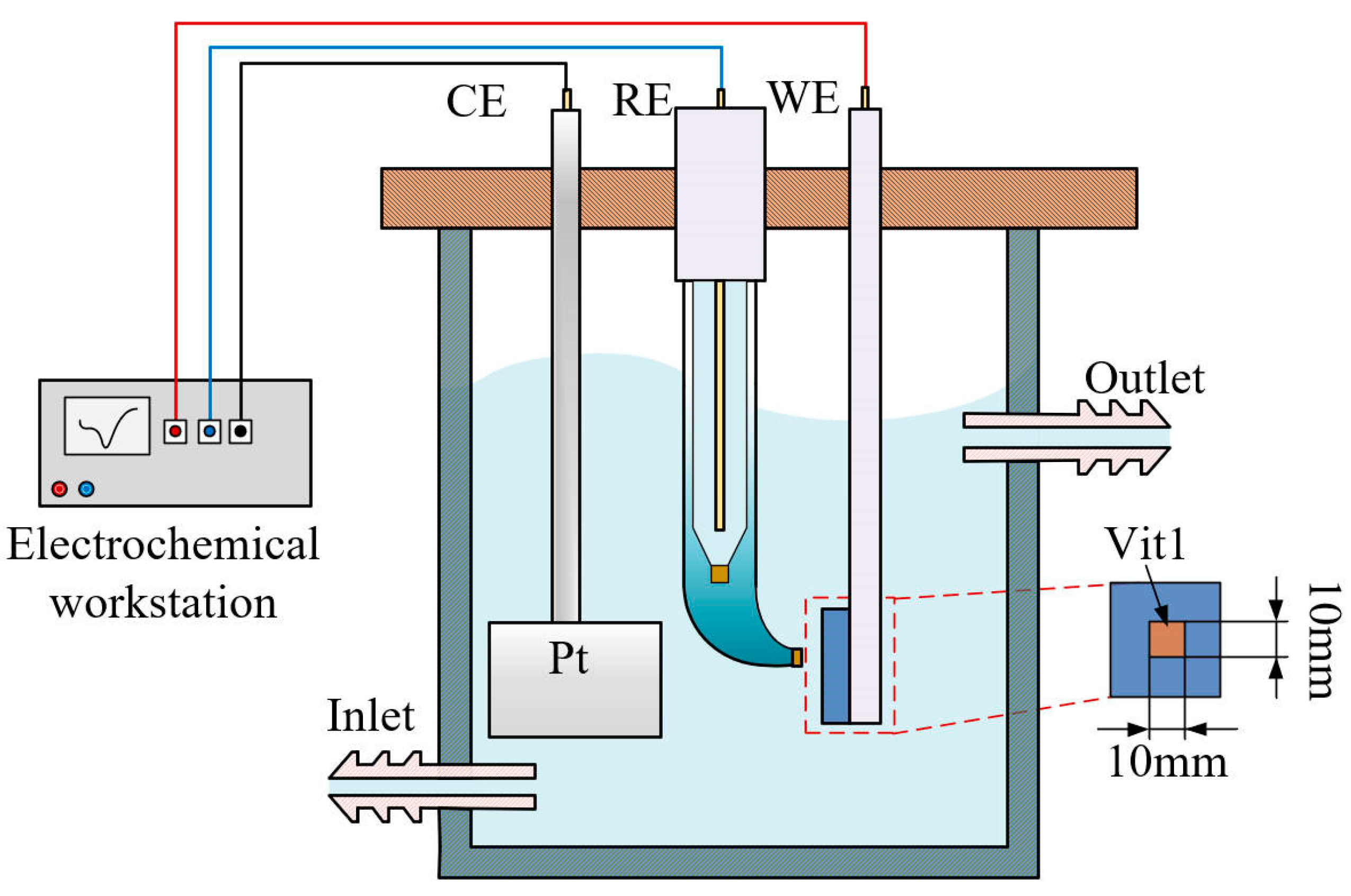
The electrochemical characteristics were measured in a three-electrode system using an electrochemical workstation (CHI604E, CH Instruments, Shanghai, China), as shown in Figure 1. A platinum plate was used as a counter electrode (CE). The reference electrode (RE) employed was Hg/Hg2Cl2, which was in contact with the electrolyte via a salt bridge to reduce the liquid junction potential. The Vit1 (10 mm (W) × 10 mm (L) × 2 mm (T)) was insulated with epoxy resin as the working electrode (WE), and only 1 cm2 of surface area was exposed to the electrolyte. The open circuit potential (OCP) was monitored in NaNO3 solution until a stable surface state was reached before the electrochemical measurements.
Polarization tests were conducted with a scan rate of 10 mV s−1. The potential range was −1 V to 3 V vs. Hg/Hg2Cl2. To obtain details of the interface structure of the passive film on the Vit1 in NaNO3 solution under different corrosion states, electrochemical impedance spectroscopy (EIS) was employed over a frequency range of 100 kHz to 0.1 Hz with a disturbance amplitude set to 5 mV. The EIS fitting data for the Zr-based MG were determined using ZView2 software.
2.3. Experimental System for Jet-ECM
The experimental setup was conducted in NaNO3 solutions using a homemade experimental system, as depicted in Figure 2. The system included a 3D XYZ stage, a power supply, an electrolyte circulation unit, and a motion control unit. The anode workpiece was the Vit1, and a hollow SUS304 nozzle was chosen as the cathode. The hollow nozzle and anode workpiece were installed on the Z-stage and XY-stage, respectively. The electrolyte was ejected from the nozzle at a relatively constant high speed by a pump. The positioning and movement operations between the anode and the cathodic substrate were precisely controlled by a computer numerical control system. A groove was machined on the surface of the Vit1 through electrochemical milling. All experiments were carried out under the conditions listed in Table 2.
2.4. Test Equipment
A field emission scanning electron microscope (Merlin Compact, Carl Zeiss NTS GmbH, Jena, Germany) was used to analyze the topography of the sample. The surface morphology and the surface roughness were measured by a confocal laser scanning microscope (OLS5100, Olympus, Tokyo, Japan). A photograph of the microstructure as obtained using a camera (Z5, Nikon, Tokyo, Japan).
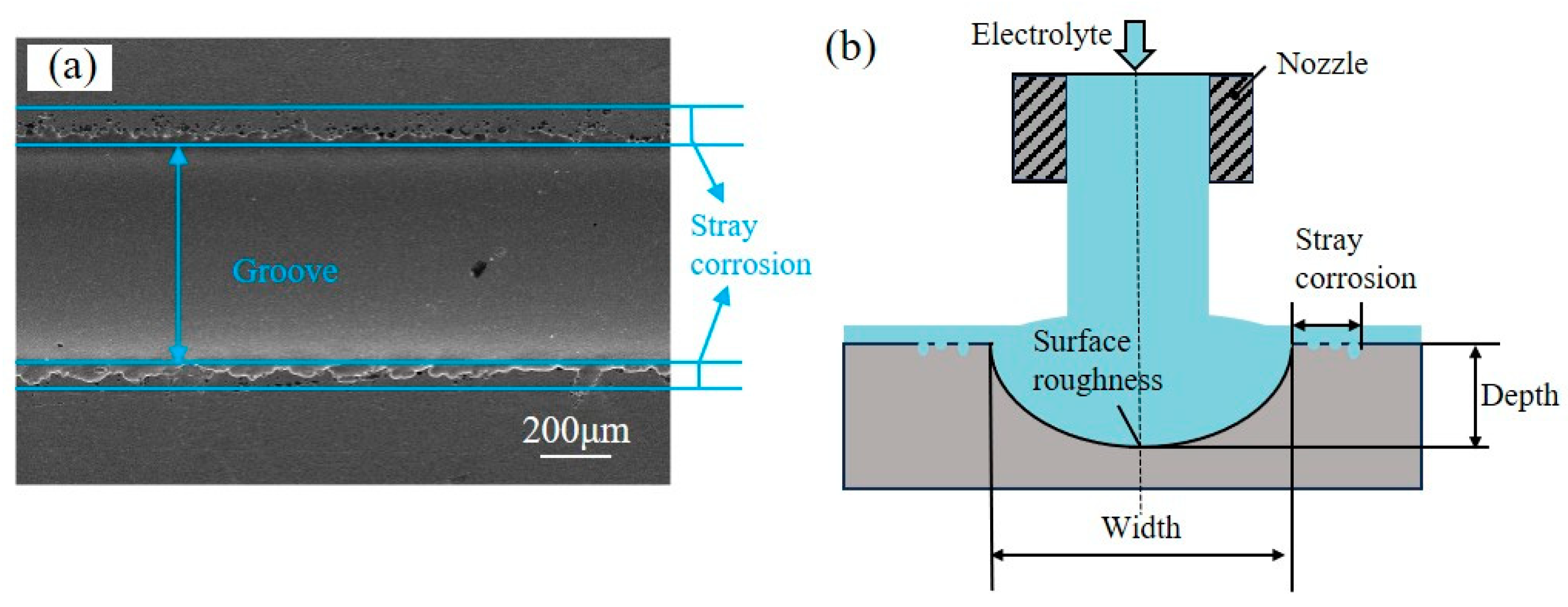
The performance evaluation criteria for machining in the experiment included width, depth, aspect ratio, surface roughness, and stray corrosion, as shown in Figure 3. The aspect ratio is defined as the ratio of depth to width. Figure 3a exhibits an SEM picture of the groove profile machined by jet-ECM with an applied voltage of 20 V and a nozzle travel rate of 100 μm/s. Stray corrosion is defined in Figure 3a.
3. Results and Discussion
3.1. Electrochemical Characteristic Analysis of the Vit1
3.1.1. Anodic Polarization Curves
The anodic electrochemical characteristics of the Vit1 in a 10 wt% NaNO3 solution at a temperature of 25 °C were investigated after the surface stabilized. A linear sweep voltammetry (LSV) curve is shown in Figure 4a. When the voltage is below 2.15 V, the passive film remains intact, and the current density does not change with increasing potential, forming a passive region. When the voltage exceeds the breakdown potential (2.15 V), the curve exhibits an ohmic (Roh) behavior [31]. The current increases with voltage, which indicates that the electrochemical dissolution enters the transpassive region. At this stage, the passive film ruptures, leading to pitting corrosion. As illustrated in Figure 4c, pits are distributed on the sample surface, resulting in a uniform and rough surface morphology.
Ecorr and Etrans are the corrosion potential and the transpassivation potential, respectively. As shown in Figure 4b, the corrosion potential is Ecorr (−0.27 V), corresponding to the minimum value of the polarization curve, which is conducive to the formation of passive film in the air. When the potential exceeds −0.27 V, the corrosion current density of the Vit1 increases rapidly, reaching 31.7 μA cm−2 at 0.13 V. When the polarization potential is between 0.13 and 1.48 V, the current density remains nearly constant, and a passive film forms on the sample surface, hindering the anodic reaction. As the potential is increased from 1.48 V to 2.15 V, the current density increases from 50.6 to 363.5 μA cm−2. When the potential exceeds Etrans (2.15 V), pitting corrosion starts to appear on the surface of the anodic specimen. Weak points in the passivation film can be penetrated. Therefore, the resistance of the passivation film decreases, leading to an increase in current.
A reverse scan was conducted to investigate the re-passivation performance of the Vit1 in NaNO3 solution. Upon reaching a potential of 3 V during the reverse scan (regions C and D), the current density rapidly decreases as the voltage descends. In the pitting area, the passive film is re-established. In the phase D–E, the deceleration in the rate of current decrease is attributed to the increase in resistance. Point D in the cyclic voltammetry curve is the intersection of the forward voltage scan and the reverse voltage scan. The presence of point D indicates that the pitting generated during the forward voltage scan is filled during the reverse scan [32].
3.1.2. Electrochemical Impedance Spectroscopy (EIS)
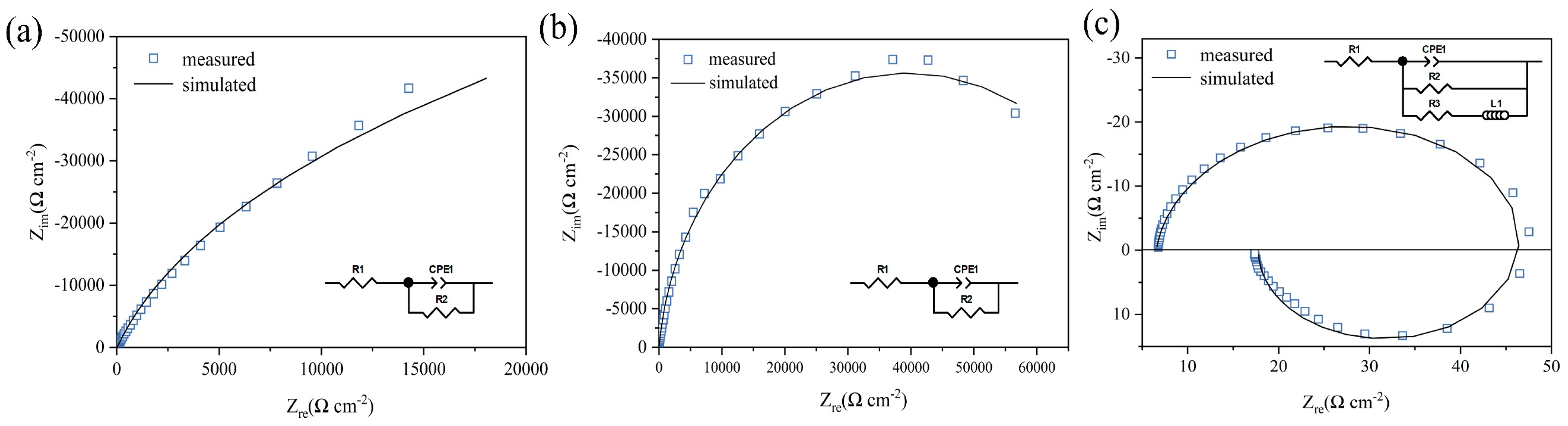
In the NaNO3 electrolyte, electrochemical impedance spectroscopy (EIS) tests were performed on three typical DC potentials in the polarization curve: 0.1 V (Tafel region), 1 V (passive region), and 2.1 V (near pitting onset) vs. Hg/Hg2Cl2.
Table 3 displays the EIS data and fitting results for the Vit1. The equivalent circuit is proposed, mainly consisting of the solution resistance (R1), charge transfer resistance (R2), constant phase element (CPE), and inductance element (L1). R1 is related to the dissolution resistance of the workpiece material. ZCPE represents the capacitance of the passivation film, which is defined as follows [33]:
where Q is the constant of the CPE, j is the imaginary number (j2 = −1), w is the angular frequency, and n is the deviation parameter, which is used to gauge surface heterogeneity. The closer n is to 1, the more uniform the surface [34,35]. The EIS data (scatter plot) and the fitting data (straight line) are shown in Figure 5. The fitted values for all the variables are listed in Table 3. At a potential of 0.1 V, the initial surface forms a monolayer of passive film, typically exhibiting a relatively dense structure. R2 exhibits the highest value, and the value of n1 is equal to 0.91, indicating the presence of pores within the typically dense internal structure of the passive film. A Nyquist plot of the polarization process at 1 V is illustrated in Figure 5b. The appearance of a semicircle is attributed to the oxidation of the base metal during the electrochemical dissolution process. As depicted in Figure 5c, increasing the polarization potential to 2.1 V leads to an evident reduction in the impedance modulus and the appearance of an inductive loop. The charge transfer resistance (R2) decreases to 44.18 Ω·cm2, indicating that the material begins to dissolve in the solution.
ZCPE = [Q(jw)n]−1
3.1.3. Discussion of the Material Removal Region in Jet-ECM
Jet-ECM processing uses a nozzle as the cathode, and an electrolyte is sprayed out from the cathode of the nozzle. The electrolyte is dispersed radially around the center of the nozzle, forming a thin layer of electrolyte of a certain thickness around the nozzle. The distribution of the electric field determines the magnitude of the current density. Low electric field intensities and current densities are distributed in regions far from the electrode center. In the high-current-density region, the passive film ruptures or reaches a dynamic equilibrium stage of transpassivation, leading to the workpiece material being rapidly removed. The passive film is regenerated in the low-current-density region [36]. The passive film prevents the material from contacting the electrolyte and thus plays a protective role.
3.2. Parametric Effects of Microgroove Fabrication by Jet-ECM
3.2.1. Effects of Applied Voltage
Applied voltage plays a crucial role in determining the precision, surface quality, and morphology characteristics in electrolytic processing. In order to investigate the effect of applied voltage on microstructural morphological changes and geometric contours, jet-ECM was carried out with the following processing parameters: a NaNO3 electrolyte concentration of 10 wt%, an initial gap of 200 μm, a nozzle travel rate of 100 μm/s, and an applied voltage of 10 to 25 V.
Figure 6 shows the microgroove morphology and cross-sectional profiles at different applied voltages. When the voltage was 10 V and 15 V, the microgroove structure contour was not clear, the width of the microgroove was only 392.4 μm and 437.5 μm, and the depth was only 47.5 μm and 78.1 μm. When the applied voltage was increased to 20 V, the material dissolution increased and the width and depth of the microgroove were 465.8 μm and 109.6 μm, respectively. When the voltage was 25 V, the width and depth of the microgroove were 475.9 μm and 119.8 μm, with less stray corrosion at the edges and a smoother bottom. The main reasons for this phenomenon are as follows: When the applied voltage is low, the passive film on the surface of the sample cannot be dissolved constantly, the amount of material removed is less, and the microgroove contour is shallower.
As shown in Figure 7, when the applied voltages were 10, 15, 20, and 25 V, the Ras were 0.211, 0.146, 0.135, and 0.129 μm, respectively. The surface roughness of Vit1 produced in the NaNO3 electrolyte is mainly dependent on the voltage applied to the machined surface, with smoother surfaces obtained at higher applied voltages. The surface roughness and stray corrosion show a decreasing trend. However, the aspect ratio gradually increases. With an increase in applied voltage from 10 V to 25 V, the aspect ratio increased from 0.121 to 0.252, the stray corrosion was reduced from 38.21 μm to 29.54 μm, and the surface roughness was changed from 0.211 μm to 0.129 μm. According to the results of studies, higher applied voltages can decrease stray corrosion and surface roughness. Consequently, 25 V was used as the applied voltage for jet-ECM of microgrooves.
3.2.2. Effects of Nozzle Travel Rate
Unlike stationary microdimples, microgrooves remove material through relative motion between the tool electrode and the workpiece. The tool electrode moves at a relatively fast rate, leading to significant changes in the electric field. However, the relative motion between the tool electrode and the workpiece is too slow and there may be excessive accumulations of products which cannot be discharged in time. Therefore, the nozzle travel rate has a significant impact on the surface quality of the machining. Jet-ECM was performed with the following machining parameters: a NaNO3 electrolyte concentration of 10 wt%, an initial gap of 200 μm, an applied voltage of 25 V, and a nozzle travel rate of 100 to 400 μm/s.
Figure 8 exhibits the machining parameters of the grooves obtained using different nozzle travel rates (100, 200, 300, and 400 μm/s). At a nozzle travel rate of 100 μm/s, the bottoms of the microgrooves exhibited relatively smooth surfaces, characterized by distinct boundaries and minimal stray corrosion. At this point, the width and depth of the microgrooves were 432.9 μm and 112.4 μm, respectively. With the increase in the nozzle travel rate, the depth of the microgrooves had a tendency to decrease gradually, and the edge contours became less clear. When the nozzle moving speed reached 400 μm/s, the fast movement caused a drastic change in the current density distribution, resulting in minimal anode material removal. Consequently, the width and depth of the microgrooves were only 454.6 μm and 44.6 μm, respectively.
The main machining quality indicators (aspect ratio, stray corrosion, and surface roughness) measured at different nozzle travel rates are shown in Figure 9. The aspect ratio decreases from 0.259 to 0.098 as the nozzle travel rate increases. Additionally, the stray corrosion range increases from 29.54 μm to 48.70 μm. Surface roughness tends to decrease from 0.128 μm to 0.120 μm. Due to the high-speed scouring of the electrolyte, the product can easily be eliminated, resulting in a smoother surface. Considering both machining efficiency and precision, better machining results are achieved at a nozzle travel rate of 100 μm/s.
3.2.3. The Dissolution Mechanism of the Zr-based MG in NaNO3
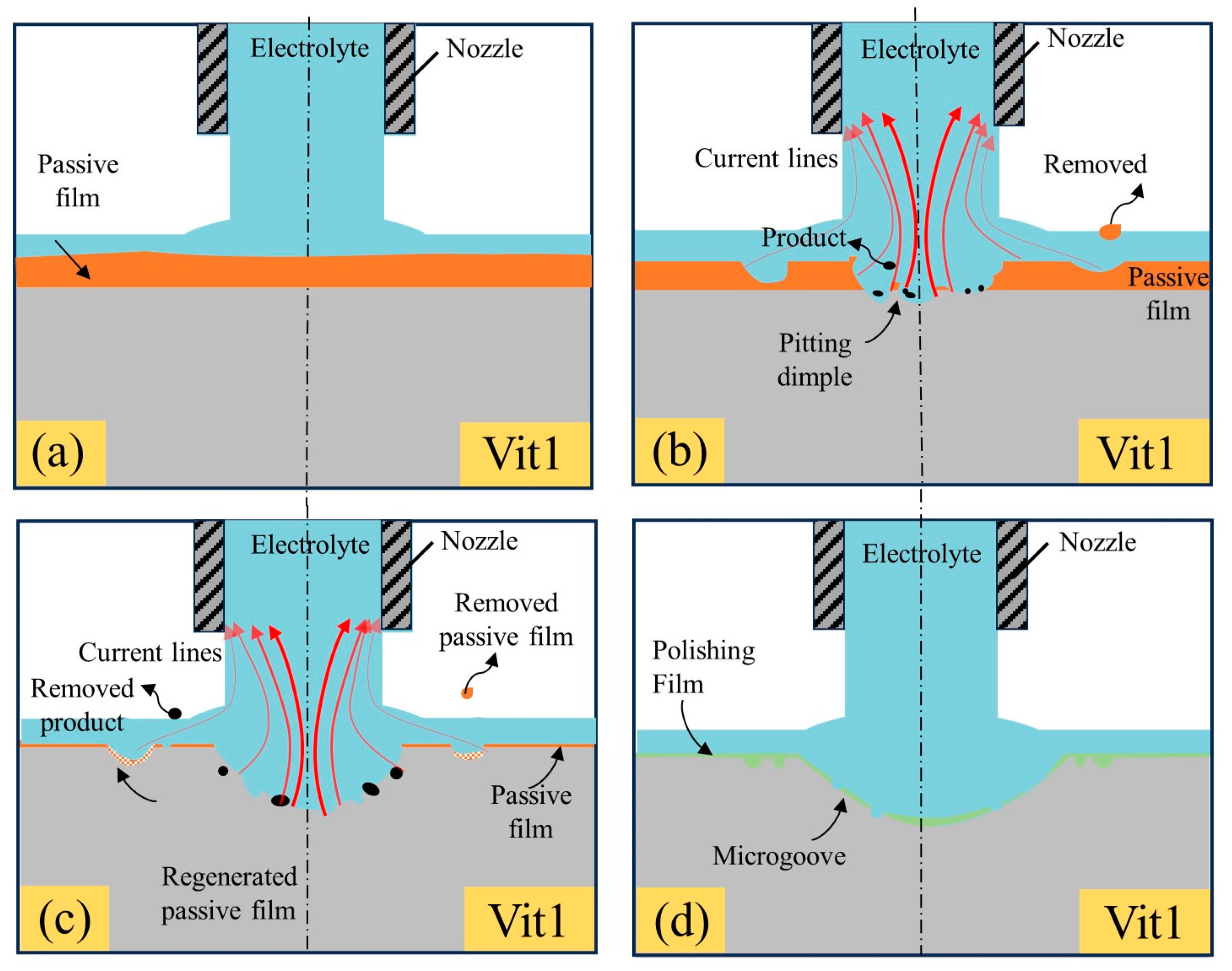
Figure 10 illustrates a possible dissolution mechanism of the Vit1 in a 10 wt% NaNO3 solution. Based on the preceding discussion of polarization properties, the Vit1 exhibited behaviors of passivation, transpassivation, and re-passivation in NaNO3 solution.
As shown in Figure 10a, the passive film is generated on the surface of Vit1 and the thickness is uneven at the initial stage. As shown in Figure 10b, the scouring action of the fast-flowing electrolyte causes rupture of the film layer, leading to local dissolution and thinning of the passive film by jet electrochemical machining [37]. In the high-current-density region, pitting occurs on the surface of the anode material and dissolution of the material occurs. In the low-current-density region, partial rupture of the passive film occurs [36].
With an increase in both the number and dimensions of pits, the localized corrosion region expands as it intersects with neighboring minor pits, ultimately leading to the removal of the passive film covering the entire anodic surface and the stable dissolution of the anode material, as shown in Figure 10c. Due to the oxidation by ions in the passive electrolyte NaNO3. In the low-current-density region, the passivation film is regenerated, which is similar to that observed during reverse scanning for cyclic voltammetry [30]. As shown in Figure 10d, the anodic surface is covered with a layer of supersaturated nitrate film, which works as a polishing film and levels the anodic surface [38].
3.3. Fabrication of Precise and Smooth Microgroove Structures
Jet-ECM can selectively remove material with the multidimensional movement of the cathode nozzle [39]. This characteristic of jet-ECM renders it a highly flexible machining technique suitable for fabricating complex microstructures. A series of experiments were conducted using the following machining parameters: an applied voltage of 25 V, an initial gap of 200μm, a nozzle travel rate of 100 μm/s, and a NaNO3 electrolyte concentration of 10 wt%.
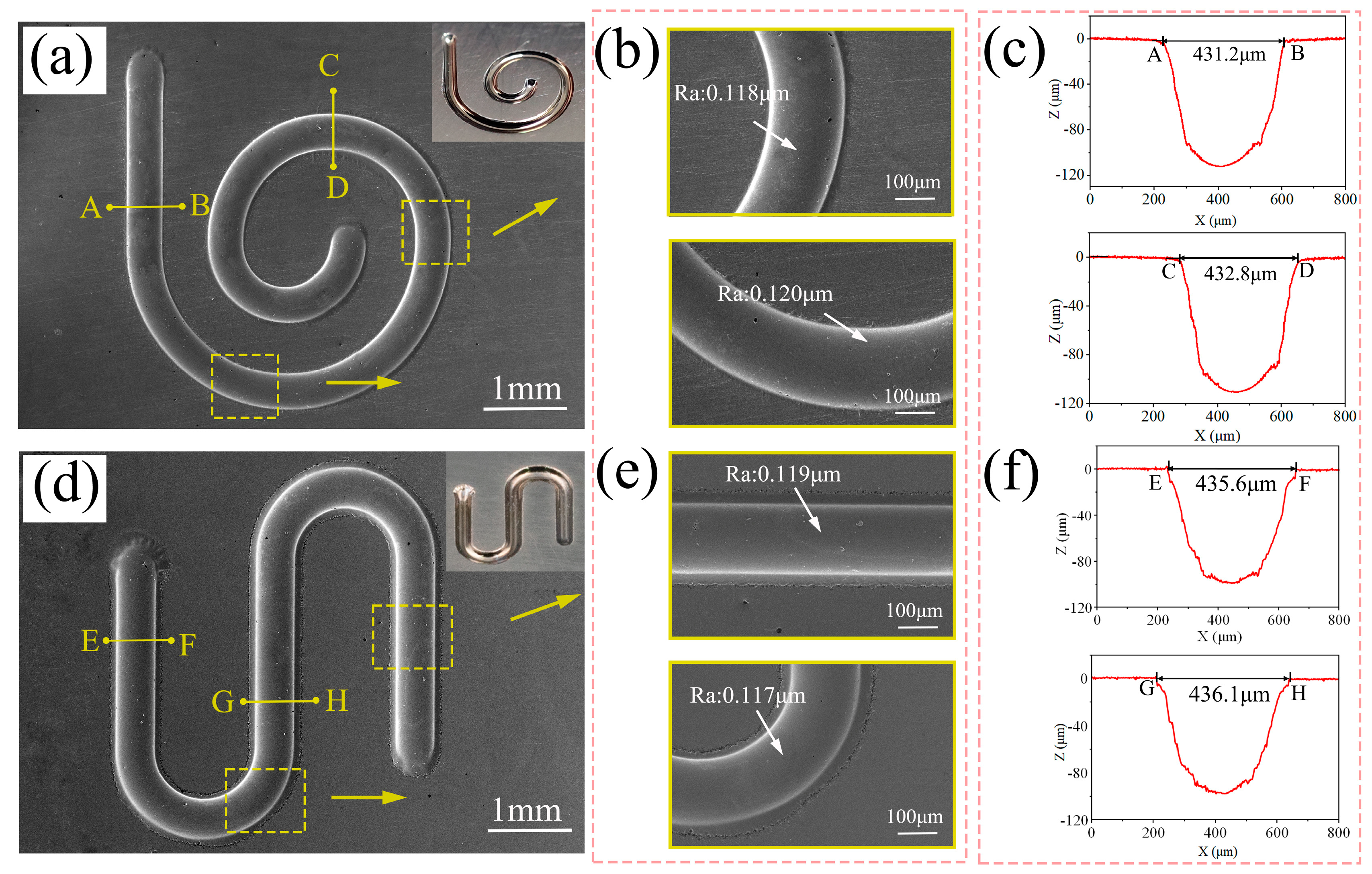
The complex microstructures fabricated on the Vit1 are depicted in Figure 11. As depicted in Figure 11a, both SEM and photographic images of the microhelical spiral are presented. The manufactured helical spiral structure exhibits clear edge contours and a smooth bottom. Figure 11b shows magnified SEM images of two regions with surface roughness values of 0.118 μm and 0.120 μm, respectively. Figure 11c displays the cross-sectional profiles of the groove bottoms in the two distinct regions. From measurements of the profiles in the cross-sections AB and CD, the results indicate microgroove widths of 431.2 µm and 432.8 µm and depths of 102.3 µm and 102.4 µm.
In Figure 11d, both SEM and photographic images of the micro-S structure are presented. Figure 11e displays magnified SEM images of two regions exhibiting surface roughness values of 0.119 μm and 0.117 μm. Figure 11f shows the cross-sectional profiles of the groove bottoms in the two distinct regions. Measurements of the profiles in the cross-sections EF and GH indicate microgroove widths of 435.6 µm and 436.1 µm, with depths of 101.1 µm and 99.8 µm. Additionally, the widths, depths, and surface roughness values of the microstructures were calculated to be 433.7 ± 2.4 µm, 101.4 ± 1.6 µm, and 0.118 ± 0.002 µm, which indicates the consistency of the contour dimensions of the fabricated microstructures. Therefore, jet electrochemical machining can manufacture precise and smooth microgroove structures on the Zr-based MG by using sodium nitrate solution.
4. Discussion
In this study, the electrochemical properties of Zr-based MG in NaNO3 solution and the feasibility of manufacturing precise and smooth microgrooves using jet-ECM were investigated. The main conclusions are summarized as follows:
- Electrochemical characteristics indicate that Zr-based MG exhibited passive, trans-passive, and re-passive performances. An applied voltage higher than the transpassivation potential is required for jet electrochemical machining of Zr-based MG.
- Jet-ECM can attain precise and smooth microgroove structures on the Zr-based metallic glass using a sodium nitrate electrolyte, with processing parameters including an applied voltage of 25 V, a nozzle travel rate of 100 μm/s, and a NaNO3 electrolyte concentration of 10 wt%.
- High geometric dimensional consistency and low surface roughness microhelical and micro-S structures can be fabricated, and their widths and depths are 433.7 ± 2.4 µm and 101.4 ± 1.6 µm, respectively. Their surface roughness is 0.118 ± 0.002 µm, which represents a significant improvement over the structures obtained by non-aqueous-based ECM processes reported earlier.
Author Contributions
Data curation, D.L., P.M., S.N., G.Y. and K.C.; funding acquisition, P.M. and S.N.; investigation, D.L. and P.M.; methodology, D.L. and P.M.; project administration, P.M.; supervision, P.M.; validation, D.L., P.M., S.N., G.Y. and K.C.; writing—original draft, D.L. and P.M.; writing—review and editing, D.L. and P.M. All authors have read and agreed to the published version of the manuscript.
Funding
This research was funded by the Scientific and Technological Innovation Leaders in Central Plains of Henan Province, grant number 214200510018; the China Postdoctoral Science Foundation, grant number 2020M682289; the Key Research and Development and Promotion Program of Henan Province, grant number 222102220001; and the Fundamental Research Funds for the Universities of Henan Province, grant number NSFRF210338.
Data Availability Statement
Data are contained within the article.
Conflicts of Interest
The authors declare no conflicts of interest.
References
- Zhang, N.; Chu, J.S.; Byrne, C.J.; Browne, D.J.; Gilchrist, M.D. Replication of Micro/Nano-Scale Features by Micro Injection Molding with a Bulk Metallic Glass Mold Insert. J. Micromech. Microeng. 2012, 22, 065019. [Google Scholar] [CrossRef]
- Becker, H.; Gärtner, C. Polymer Microfabrication Technologies for Microfluidic Systems. Anal. Bioanal. Chem. 2008, 390, 89–111. [Google Scholar] [CrossRef] [PubMed]
- Kukharenka, E.; Farooqui, M.M.; Grigore, L.; Kraft, M.; Hollinshead, N. Electroplating Moulds Using Dry Film Thick Negative Photoresist. J. Micromech. Microeng. 2003, 13, S67. [Google Scholar] [CrossRef]
- Bourne, G.R.; Bardt, J.; Sawyer, W.G.; Ziegert, J.; Zeenberg, D.; Schmitz, T. Closed Channel Fabrication Using Micromolding of Metallic Glass. J. Mater. Process. Technol. 2009, 209, 4765–4768. [Google Scholar] [CrossRef]
- Hupert, M.L.; Guy, W.J.; Llopis, S.D.; Shadpour, H.; Rani, S.; Nikitopoulos, D.E.; Soper, S.A. Evaluation of Micromilled Metal Mold Masters for the Replication of Microchip Electrophoresis Devices. Microfluid. Nanofluid 2006, 3, 1–11. [Google Scholar] [CrossRef]
- Saotome, Y.; Imai, K.; Shioda, S.; Shimizu, S.; Zhang, T.; Inoue, A. The Micro-Nanoformability of Pt-Based Metallic Glass and the Nanoforming of Three-Dimensional Structures. Intermetallics 2002, 10, 1241–1247. [Google Scholar] [CrossRef]
- Gong, Y.D.; Liu, Y.; Sun, Y.; Wen, X.L.; Li, Q.; Qu, S.S.; Cai, M. Experimental and Emulational Investigations into Grinding Characteristics of Zr-Based Bulk Metallic Glass (BMG) Using Microgrinding. Int. J. Adv. Manuf. Technol. 2018, 97, 3431–3451. [Google Scholar]
- Inoue, A. Stabilization of Metallic Supercooled Liquid and Bulk Amorphous Alloys. Acta Materialia 2000, 48, 279–306. [Google Scholar] [CrossRef]
- Wei, Z.; Miao, H.T.; Li, Y.H.; Chang, C.T.; Xie, G.Q.; Jia, X.J. Glass-Forming Ability and Thermoplastic Formability of Ferromagnetic (Fe, Co, Ni)75P10C10B5 Metallic Glasses. J. Alloys Compd. 2017, 707, 57–62. [Google Scholar]
- Bakkal, M.; Shih, A.J.; McSpadden, S.B.; Scattergood, R.O. Thrust Force, Torque, and Tool Wear in Drilling the Bulk Metallic Glass. Int. J. Mach. Tools Manuf. 2005, 45, 863–872. [Google Scholar] [CrossRef]
- Bakkal, M.; Shih, A.J.; McSpadden, S.B.; Liu, C.T.; Scattergood, R.O. Light Emission, Chip Morphology, and Burr Formation in Drilling the Bulk Metallic Glass. Int. J. Mach. Tools Manuf. 2005, 45, 741–752. [Google Scholar] [CrossRef]
- Williams, E.; Lavery, N. Laser Processing of Bulk Metallic Glass: A Review. J. Mater. Process. Technol. 2017, 247, 73–91. [Google Scholar] [CrossRef]
- Pradana, Y.; Ferara, A.; Aminnudin, A.; Wahono, W.; Jang, S.C. The Effect of Discharge Current and Pulse-On Time on Biocompatible Zr-Based BMG Sinking-EDM. Open Engineering 2020, 10, 401–407. [Google Scholar] [CrossRef]
- Ding, F.; Wang, C.Y.; Zhang, T.; Zheng, L.J.; Zhu, X.G. High Performance Cutting of Zr-Based Bulk Metallic Glass: A Review of Chip Formation. Procedia CIRP 2018, 77, 421–424. [Google Scholar] [CrossRef]
- Schuster, R.; Kirchner, V.; Allongue, P.; Ertl, G. Electrochemical Micromachining. Science 2000, 289, 98–101. [Google Scholar] [CrossRef] [PubMed]
- Hsieh, S.F.; Chen, S.L.; Lin, M.H.; Ou, S.F.; Lin, W.T.; Huang, M.-S. Crystallization and Carbonization of an Electrical Discharge Machined Zr-Based Bulk Metallic Glass Alloy. J. Mater. Res. 2013, 28, 3177–3184. [Google Scholar] [CrossRef]
- Huang, H.; Yan, J.W. Microstructural Changes of Zr-Based Metallic Glass during Micro-Electrical Discharge Machining and Grinding by a Sintered Diamond Tool. J. Alloys Compd. 2016, 688, 14–21. [Google Scholar] [CrossRef]
- Huang, H.; Yan, J.W. On the Surface Characteristics of a Zr-Based Bulk Metallic Glass Processed by Microelectrical Discharge Machining. Appl. Surf. Sci. 2015, 355, 1306–1315. [Google Scholar] [CrossRef]
- Koza, J.A.; Sueptitz, R.; Uhlemann, M.; Schultz, L.; Gebert, A. Electrochemical Micromachining of a Zr-Based Bulk Metallic Glass Using a Micro-Tool Electrode Technique. Intermetallics 2011, 19, 437–444. [Google Scholar] [CrossRef]
- Gebert, A.; Gostin, P.F.; Sueptitz, R.; Oswald, S.; Abdi, S.; Uhlemann, M.; Eckert, J. Polarization Studies of Zr-Based Bulk Metallic Glasses for Electrochemical Machining. J. Electrochem. Soc. 2014, 161, E66. [Google Scholar] [CrossRef]
- Cole, K.M.; Kirk, D.W.; Singh, C.V.; Thorpe, S.J. Optimizing Electrochemical Micromachining Parameters for Zr-Based Bulk Metallic Glass. J. Manuf. Process. 2017, 25, 227–234. [Google Scholar] [CrossRef]
- Guo, C.; Wu, B.; Xu, B.; Wu, S.; Shen, J.; Wu, X. Investigation of Pulse Electrochemical Machining of Zr-Based Bulk Metallic Glasses in NaNO3 -Ethylene Glycol Electrolyte. J. Electrochem. Soc. 2021, 168, 071502. [Google Scholar] [CrossRef]
- Guo, C.; He, J.; Zhuang, W.; Li, K.; Li, D. Fabrication of Dimples by Jet-ECM of Zr-Based Bulk Metallic Glasses with NaCl-Ethylene Glycol Electrolyte. Micromachines 2023, 14, 2196. [Google Scholar] [CrossRef] [PubMed]
- Guo, C.; Zhou, A.; He, J.; Xiao, H.; Li, D. An Investigation in Sub-Millimeter Channel Fabrication by the Non-Aqueous Electrolyte Jet Machining of Zr-Based Bulk Metallic Glasses. Micromachines 2023, 14, 2232. [Google Scholar] [CrossRef] [PubMed]
- Hang, Y.S.; Zeng, Y.B.; Yang, T.; Meng, L.C. The Dissolution Characteristics and Wire Electrochemical Micromachining of Metallic Glass Ni82Cr7Si5Fe3B3. J. Manuf. Process. 2020, 58, 884–893. [Google Scholar] [CrossRef]
- Zhu, D.; Zeng, Y.B.; Xu, Z.Y.; Zhang, X.Y. Precision Machining of Small Holes by the Hybrid Process of Electrochemical Removal and Grinding. CIRP Annals 2011, 60, 247–250. [Google Scholar] [CrossRef]
- Meng, L.C.; Zeng, Y.B.; Zhu, D. Investigation on Wire Electrochemical Micro Machining of Ni-Based Metallic Glass. Electrochim. Acta 2017, 233, 274–283. [Google Scholar] [CrossRef]
- Yang, T.; Li, Y.L.; Xu, Z.Y.; Zeng, Y.B. Electrochemical Cutting with Inner-Jet Electrolyte Flushing for Titanium Alloy (Ti-6Al-4V). Int. J. Adv. Manuf. Technol. 2021, 112, 2583–2592. [Google Scholar] [CrossRef]
- Hackert-Oschätzchen, M.; Meichsner, G.; Zinecker, M.; Martin, A.; Schubert, A. Micro Machining with Continuous Electrolytic Free Jet. Precis. Eng. 2012, 36, 612–619. [Google Scholar] [CrossRef]
- Liu, W.D.; Ao, S.S.; Li, Y.; Liu, Z.M.; Zhang, H.; Manladan, S.M.; Luo, Z.; Wang, Z.P. Effect of Anodic Behavior on Electrochemical Machining of TB6 Titanium Alloy. Electrochim. Acta 2017, 233, 190–200. [Google Scholar] [CrossRef]
- Wang, D.Y.; Zhu, Z.W.; Wang, N.F.; Zhu, D.; Wang, H.R. Investigation of the Electrochemical Dissolution Behavior of Inconel 718 and 304 Stainless Steel at Low Current Density in NaNO3 Solution. Electrochim. Acta 2015, 156, 301–307. [Google Scholar] [CrossRef]
- Liu, Y.; Qu, N.S. Electrochemical Milling of TB6 Titanium Alloy in NaNO3 Solution. J. Electrochem. Soc. 2019, 166, E35–E49. [Google Scholar] [CrossRef]
- Bolzoni, F.M.; Diamanti, M.V.; Ormellese, M.; Pedeferri, M.P.; Pérez-Rosales, E. Characterisation of Titanium Oxide Films By Potentiodynamic Polarization And Electrochemical Impedance Spectroscopy. Corros. Eng. Sci. Technol. 2010, 45, 428–434. [Google Scholar]
- Wang, J.T.; Xu, Z.Y.; Wang, J.; Zhu, D. Anodic Dissolution Characteristics of Inconel 718 in C6H5K3O7 and NaNO3 Solutions by Pulse Electrochemical Machining. Corros. Sci. 2021, 183, 109335. [Google Scholar] [CrossRef]
- Herraiz-Cardona, I.; Ortega, E.; Antón, J.G.; Pérez-Herranz, V. Assessment of the Roughness Factor Effect and the Intrinsic Catalytic Activity for Hydrogen Evolution Reaction on Ni-Based Electrodeposits. Int. J. Hydrogen Energy 2011, 36, 9428–9438. [Google Scholar] [CrossRef]
- Liu, G.D.; Tong, H.; Li, Y.; Tan, Q.F.; Zhu, Y.L. Passivation Behavior of S136H Steel in Neutral Electrolytes Composed of NaClO3 and NaNO3 and Its Influence on Micro Electrochemical Machining Performance. Mater. Today Commun. 2021, 29, 102762. [Google Scholar] [CrossRef]
- Schultze, J.W.; Lohrengel, M.M. Stability, Reactivity and Breakdown of Passive Films. Problems of Recent and Future Research. Electrochim. Acta 2000, 45, 2499–2513. [Google Scholar] [CrossRef]
- Rosenkranz, C.; Lohrengel, M.M.; Schultze, J.W. The Surface Structure during Pulsed ECM of Iron in NaNO3. Electrochim. Acta 2005, 50, 2009–2016. [Google Scholar] [CrossRef]
- Liu, W.D.; Luo, Z.; Li, Y.; Liu, Z.M.; Li, K.B.; Xu, J.X.; Ao, S.S. Investigation on Parametric Effects on Groove Profile Generated on Ti1023 Titanium Alloy by Jet Electrochemical Machining. Int. J. Adv. Manuf. Technol. 2019, 100, 2357–2370. [Google Scholar] [CrossRef]
Figure 1.
Electrochemical measurement setup.

Figure 2.
The experimental setup for processing the Vit1 by jet-ECM.
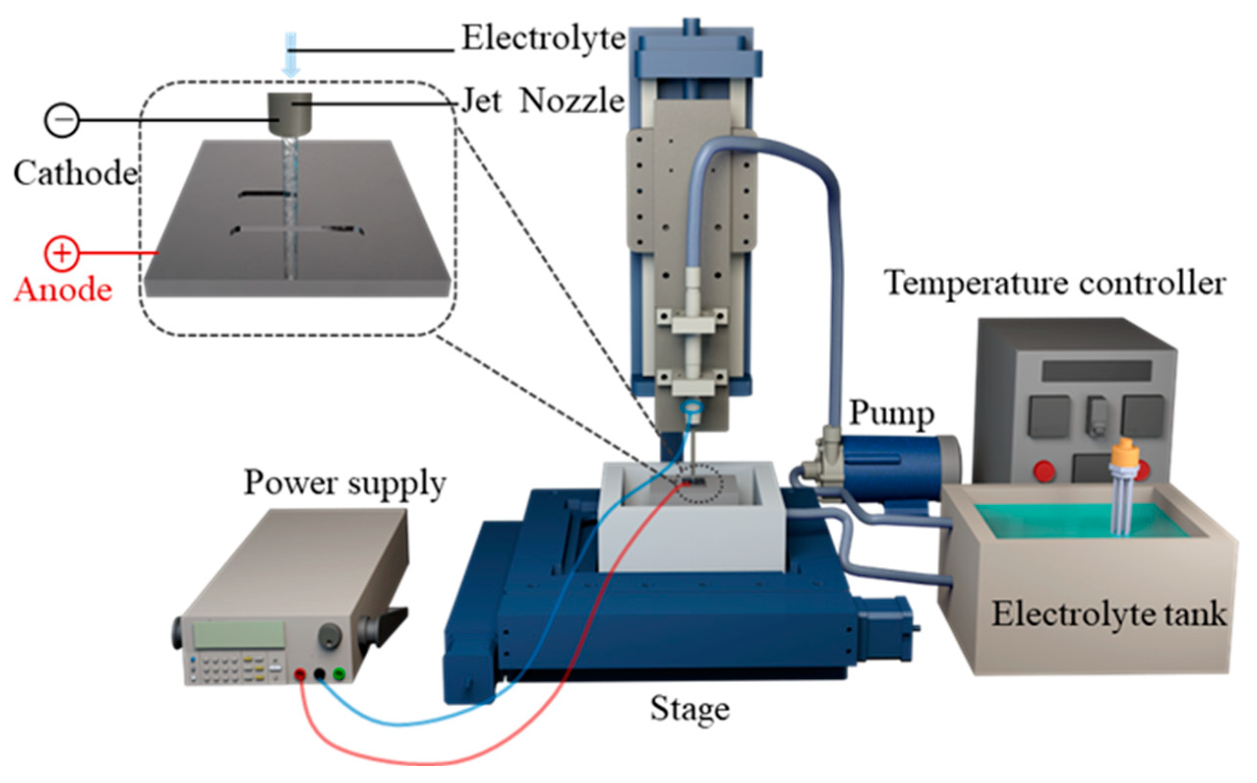
Figure 3.
Profile of the machined groove: (a) SEM picture of the detailed stray corrosion; (b) schematic of performance evaluation indices.
Figure 3.
Profile of the machined groove: (a) SEM picture of the detailed stray corrosion; (b) schematic of performance evaluation indices.

Figure 4.
Polarization curve of the Vit1 in NaNO3 solution: (a) linear sweep voltammetry curve; (b) cyclic voltammetry curve; (c) SEM image of the transpassive region.
Figure 4.
Polarization curve of the Vit1 in NaNO3 solution: (a) linear sweep voltammetry curve; (b) cyclic voltammetry curve; (c) SEM image of the transpassive region.
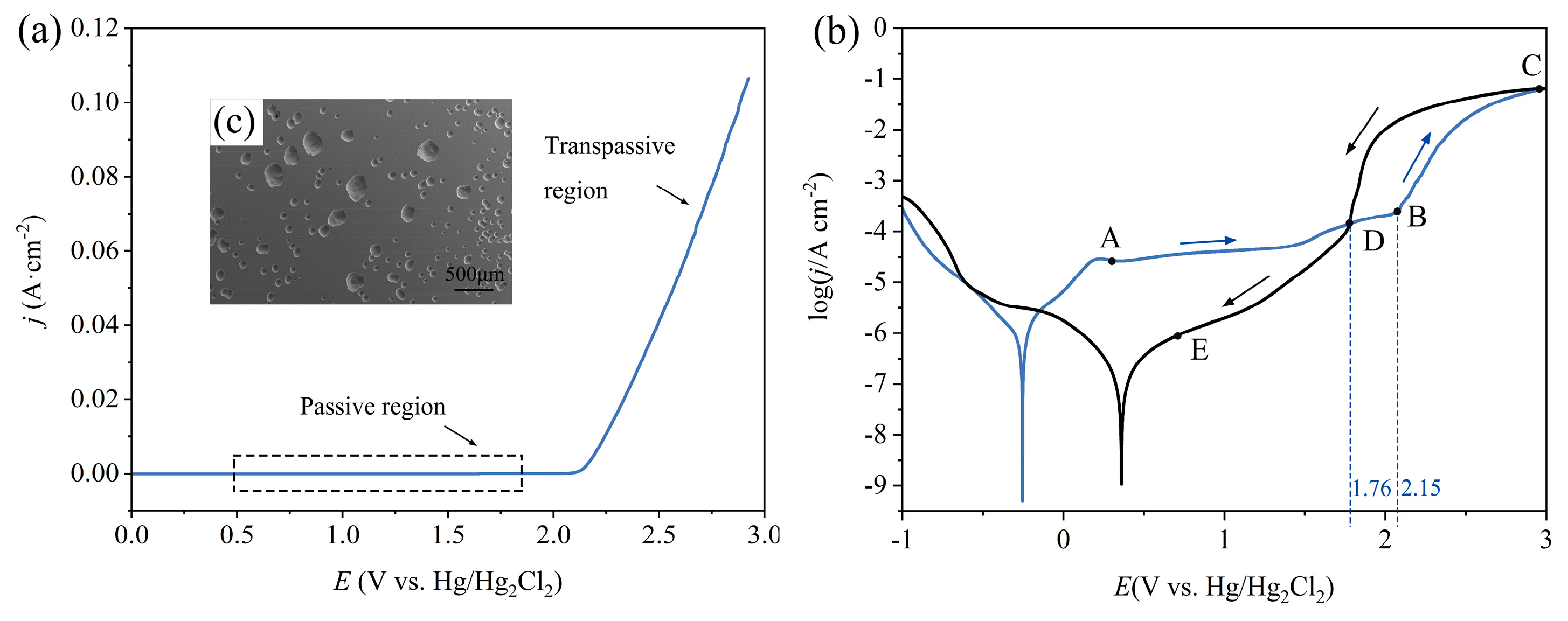
Figure 5.
EIS results during polarization at different potentials: (a) 0.1 V; (b) 1 V; (c) 2.1 V.

Figure 6.
Morphology and profiles of microgrooves at different applied voltages.
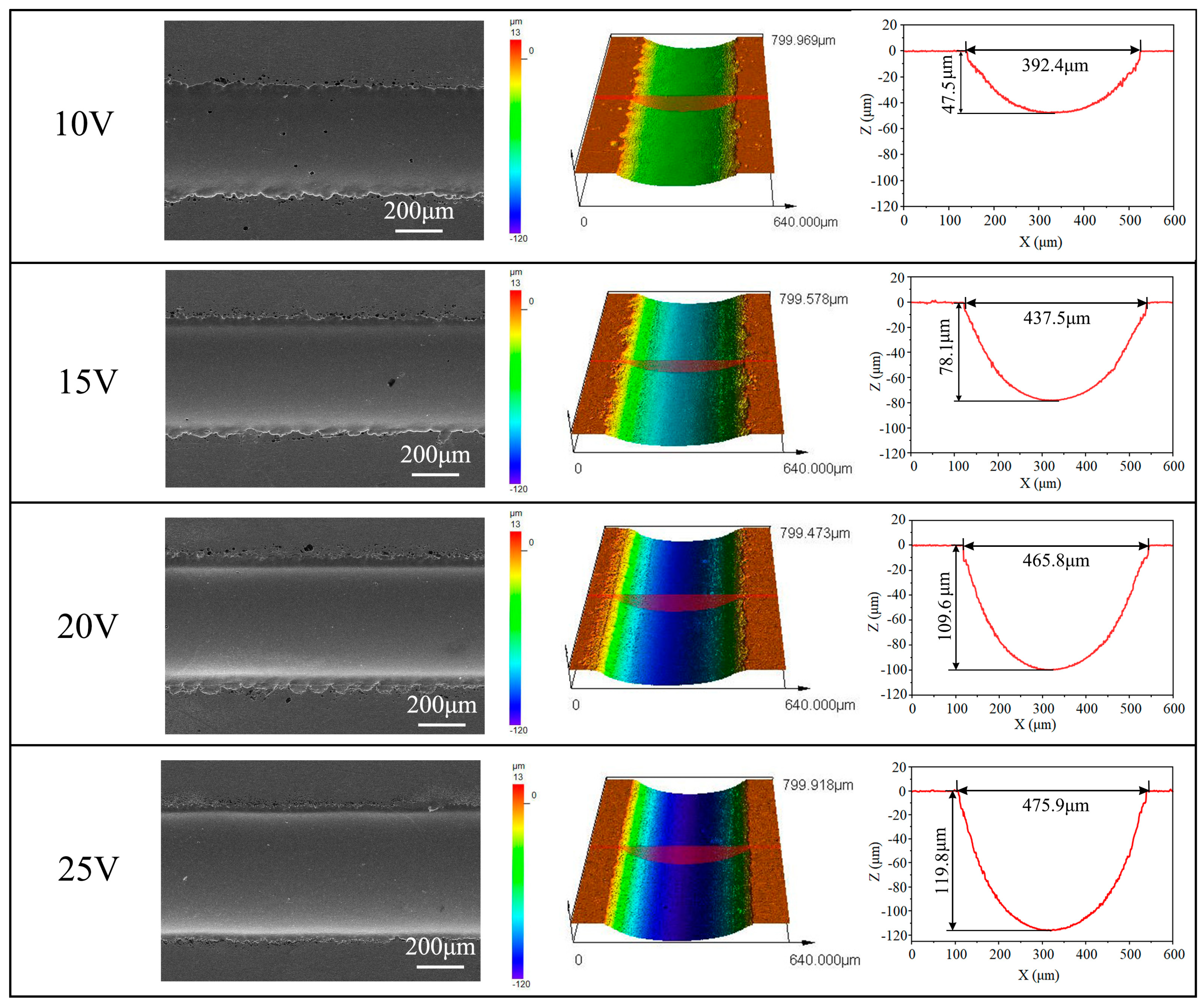
Figure 7.
Influence of applied voltage on machining performance.
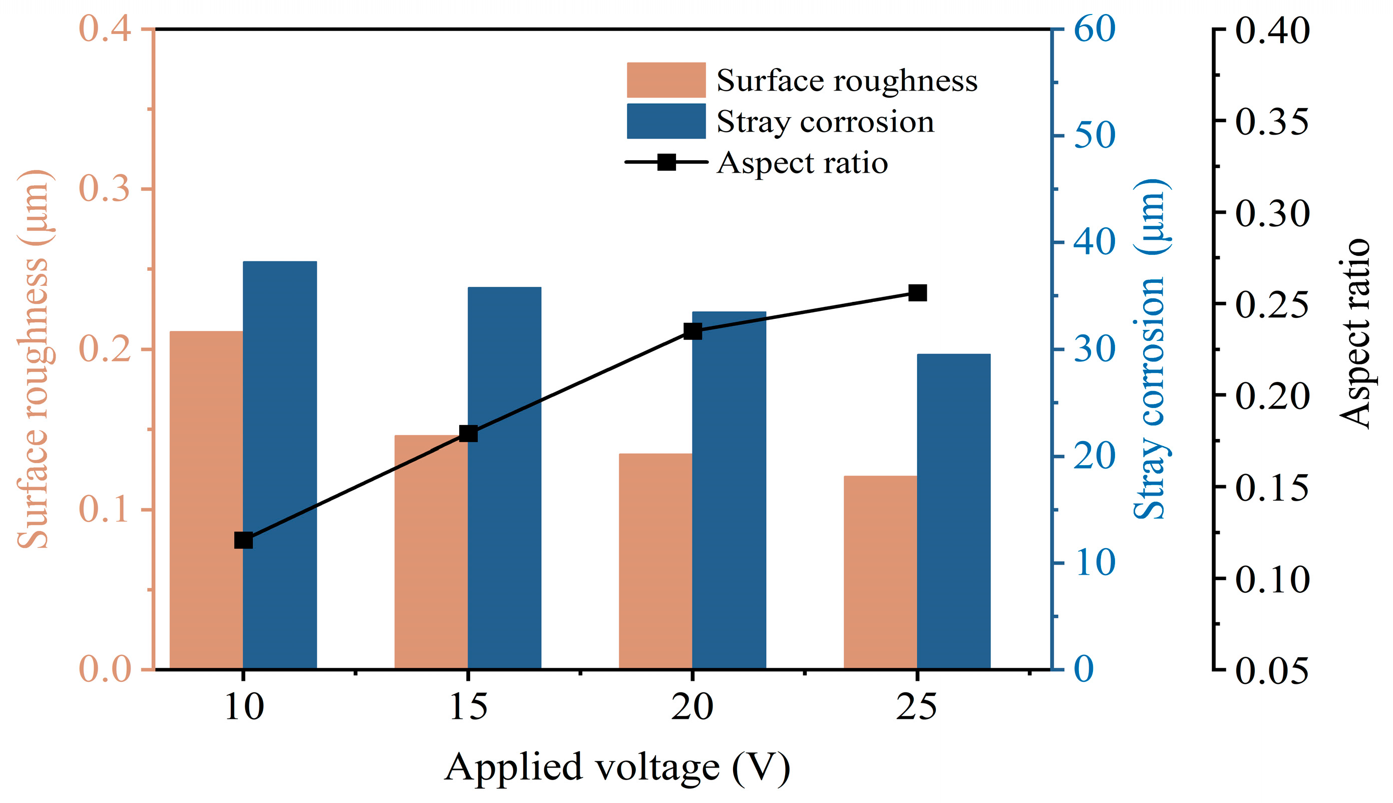
Figure 8.
Morphology and profiles of microgrooves at different nozzle travel rates.
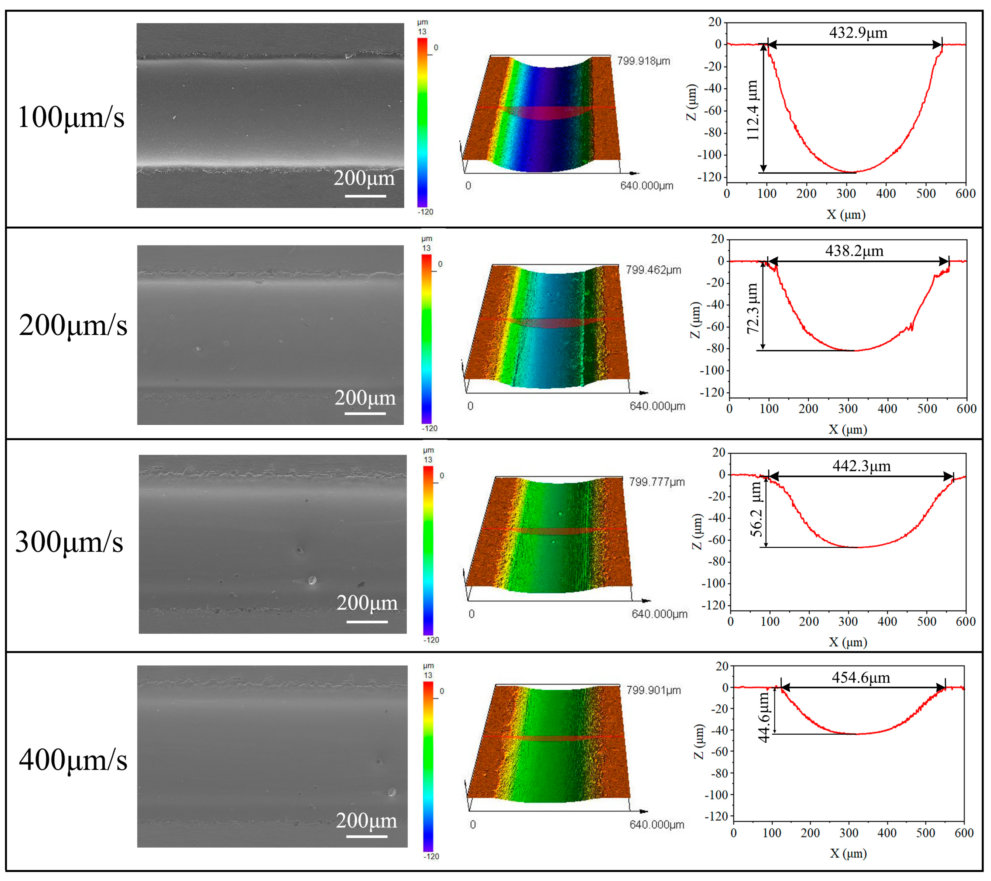
Figure 9.
Influence of nozzle travel rate on machining performance.
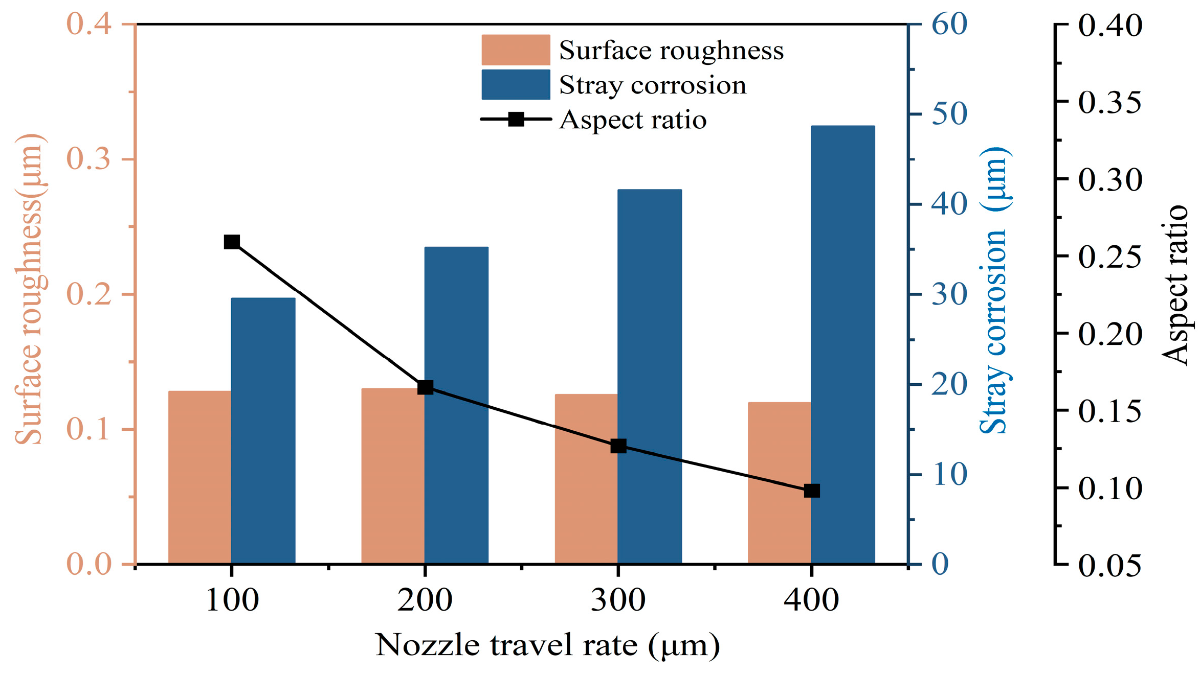
Figure 10.
(a–d) Schematic of the dissolution mechanism of the Vit1 in 10 wt% NaNO3 solution.

Figure 11.
(a–f) Complex microstructures fabricated on the Vit1 by jet-ECM.


Table 1.
Properties of the Zr-based MG.
| Parameters | Value |
|---|---|
| Specific conductance (Ms/m) | 0.52–0.53 |
| Young’s modulus (GPa) | 94.9 |
| Poisson ratio | 0.30 |
| Hardness (HV) | 568–619 |
Table 2.
Processing conditions for jet-ECM.
| Parameters | Value |
|---|---|
| Material | Zr41.2Ti13.8Cu12.5Ni10.0Be22.5 |
| Tool electrode | SUS 304 nozzle |
| Inner diameter of nozzle | 220 ± 2 μm |
| Outer diameter of nozzle | 450 ± 3 μm |
| Electrolyte composition | 10 wt% NaNO3 |
| Machining gap (μm) | 200 |
| Electrolyte pressure (MPa) | 1 |
| Machining voltage (V) | 10, 15, 20, 25, |
| Nozzle travel rate (μm/s) | 100, 200, 300, 400 |
| Temperature of electrolyte (°C) | 25 ± 5 |
Table 3.
Fitting results of the Vit1.
| Potential (V) | R1 (Ω cm−2) | Q1 × 10−6 (snΩ−1 cm−2) | n1 | R2 (Ω cm−2) | R3 (Ω cm−2) | L1 (H cm−2) |
|---|---|---|---|---|---|---|
| 0.1 | 16.36 | 17.96 | 0.91 | 182,770 | - | - |
| 1 | 8.49 | 8.13 | 0.93 | 78,989 | - | - |
| 2.1 | 6.55 | 10.21 | 0.93 | 44.18 | 15.06 | 0.064 |
Disclaimer/Publisher’s Note: The statements, opinions and data contained in all publications are solely those of the individual author(s) and contributor(s) and not of MDPI and/or the editor(s). MDPI and/or the editor(s) disclaim responsibility for any injury to people or property resulting from any ideas, methods, instructions or products referred to in the content. |
© 2024 by the authors. Licensee MDPI, Basel, Switzerland. This article is an open access article distributed under the terms and conditions of the Creative Commons Attribution (CC BY) license (https://creativecommons.org/licenses/by/4.0/).
Share and Cite
MDPI and ACS Style
Li, D.; Ming, P.; Niu, S.; Yang, G.; Cheng, K. Fabricating Precise and Smooth Microgroove Structures on Zr-Based Metallic Glass Using Jet-ECM. Micromachines 2024, 15, 497. https://doi.org/10.3390/mi15040497
AMA Style
Li D, Ming P, Niu S, Yang G, Cheng K. Fabricating Precise and Smooth Microgroove Structures on Zr-Based Metallic Glass Using Jet-ECM. Micromachines. 2024; 15(4):497. https://doi.org/10.3390/mi15040497
Chicago/Turabian StyleLi, Dongdong, Pingmei Ming, Shen Niu, Guangbin Yang, and Kuaile Cheng. 2024. "Fabricating Precise and Smooth Microgroove Structures on Zr-Based Metallic Glass Using Jet-ECM" Micromachines 15, no. 4: 497. https://doi.org/10.3390/mi15040497
Note that from the first issue of 2016, this journal uses article numbers instead of page numbers. See further details here.