
Flexible Electronics: Advancements and Applications of Flexible Piezoelectric Composites in Modern Sensing Technologies
 ,
, 
Abstract
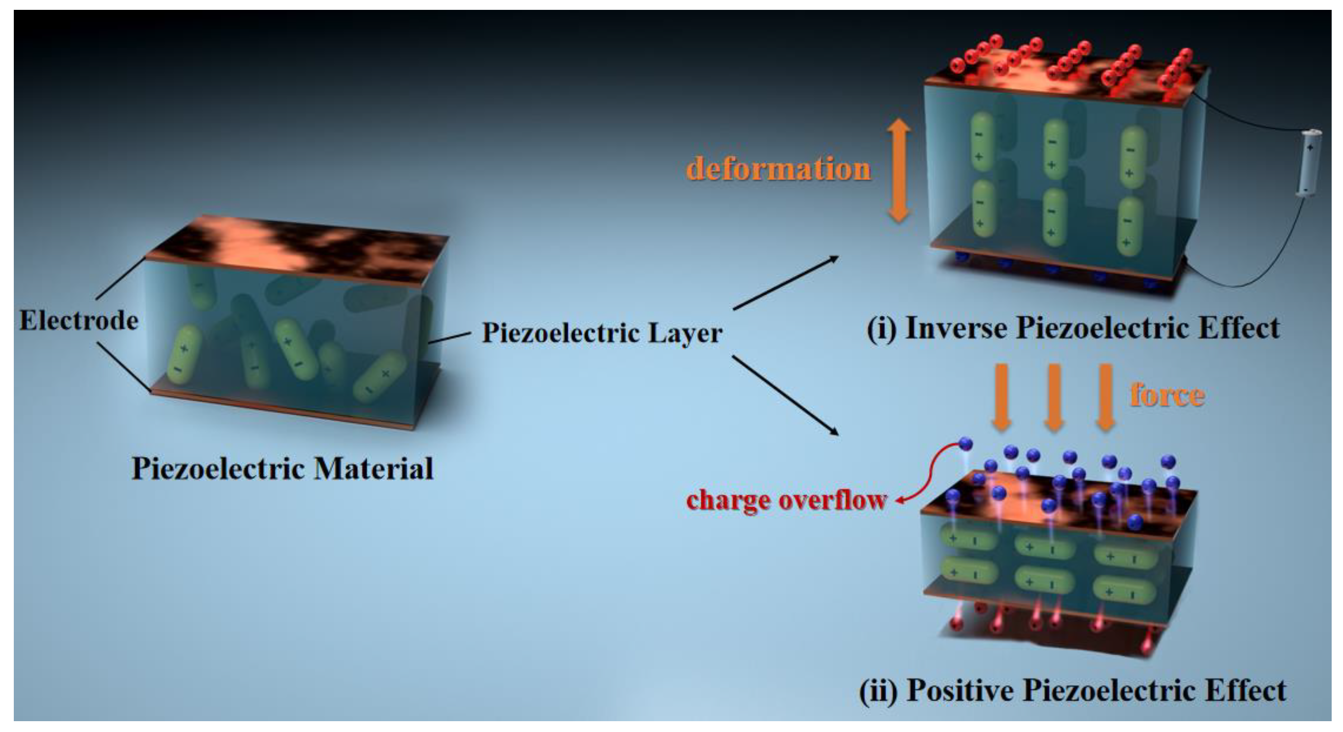
:1. Introduction
2. Types of Flexible Piezoelectric Composite Materials
2.1. 0-3 Type
2.1.1. PVDF Series Matrix Type
2.1.2. Non PVDF Series Matrix Type
2.2. 1-3 Type
2.3. Special Structural Design
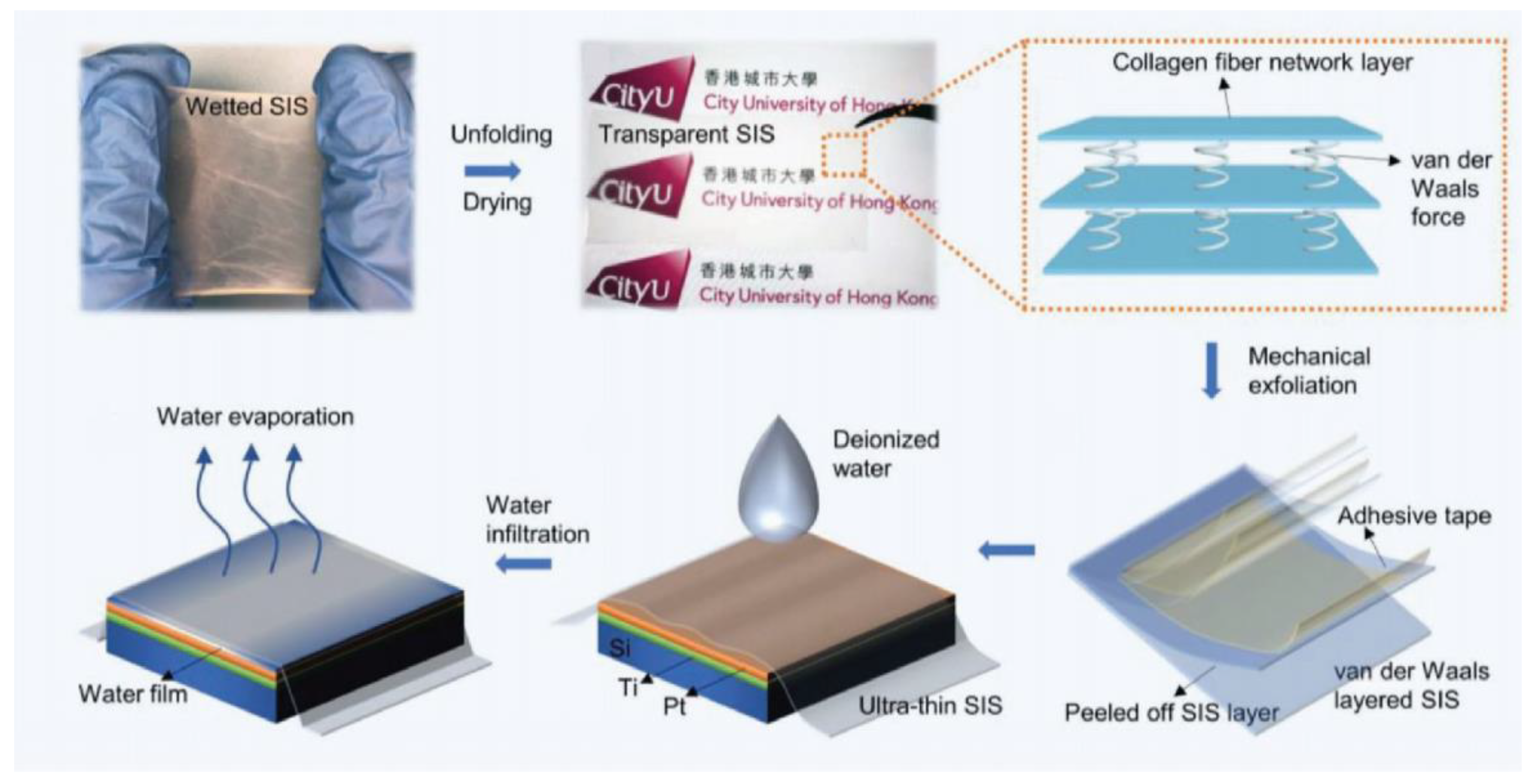
2.4. Flexible Piezoelectric Composite Biomaterials
3. Fabrication Process of Flexible Piezoelectric Composite Materials
3.1. Fabrication Process
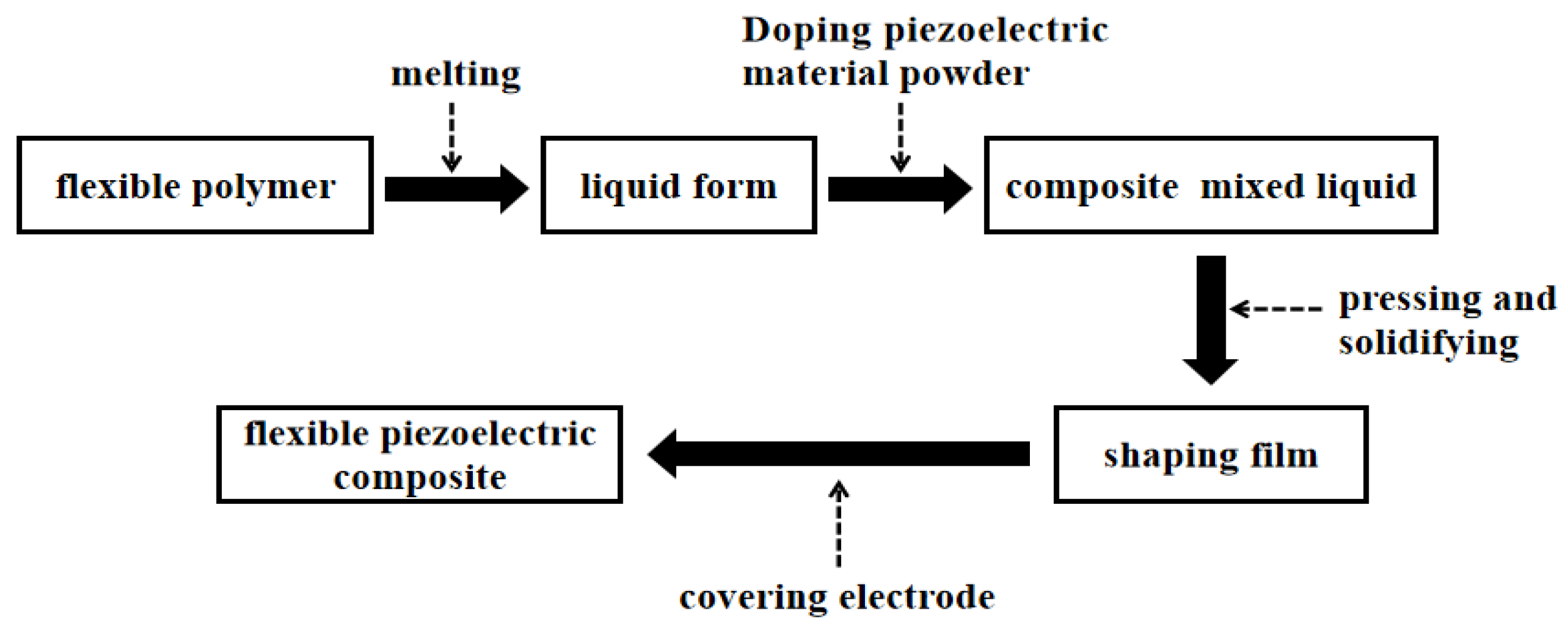
3.1.1. Molding by Hot Pressing
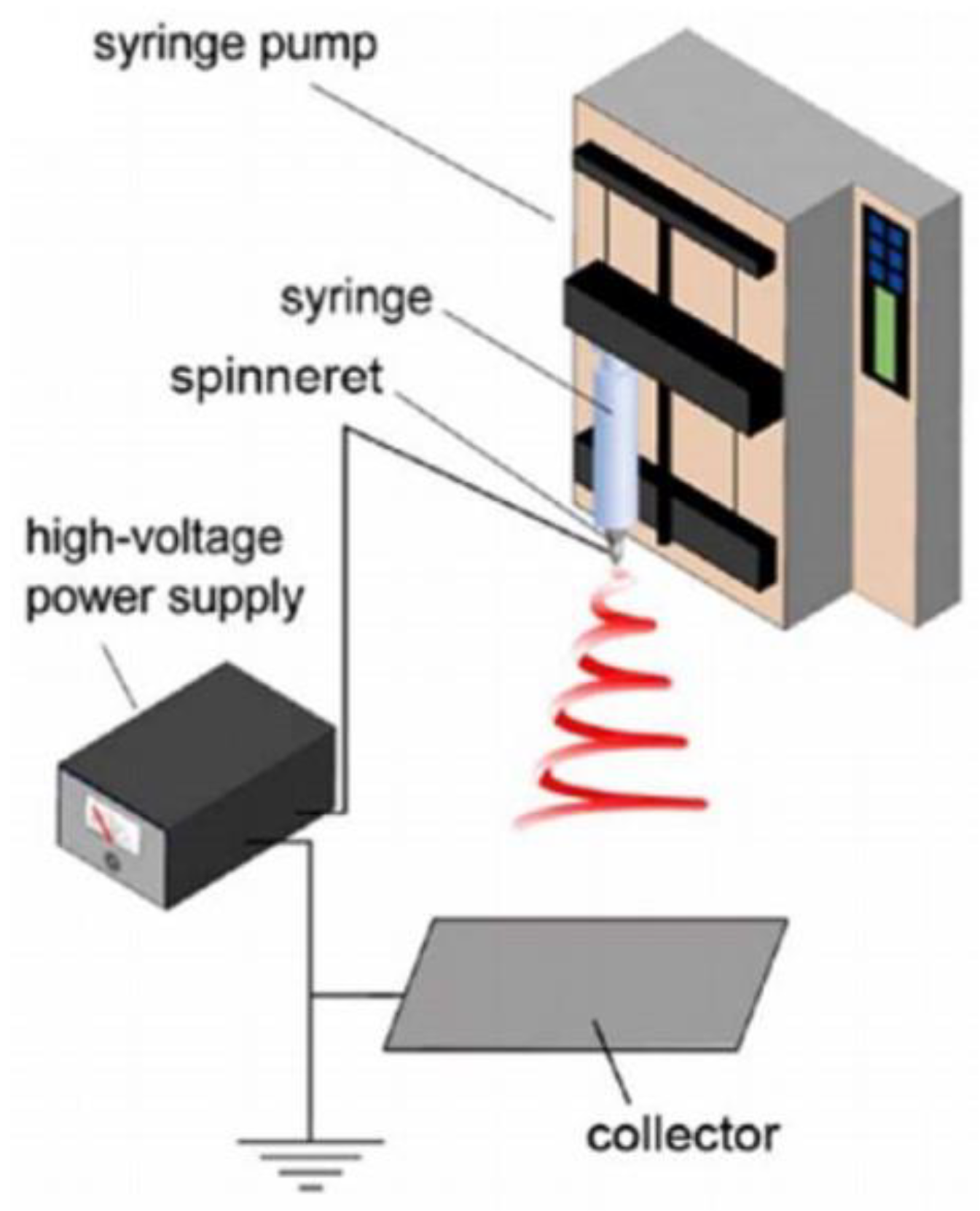
3.1.2. Electrospinning
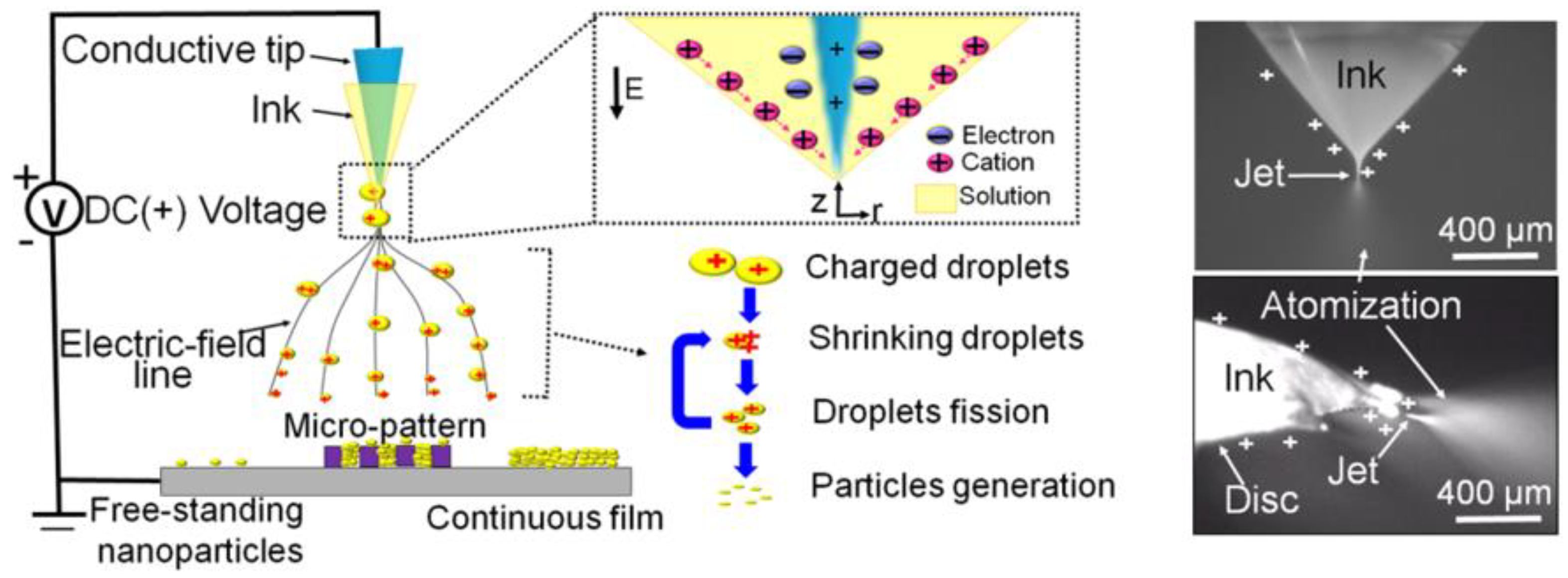
3.1.3. Electrospray Deposition
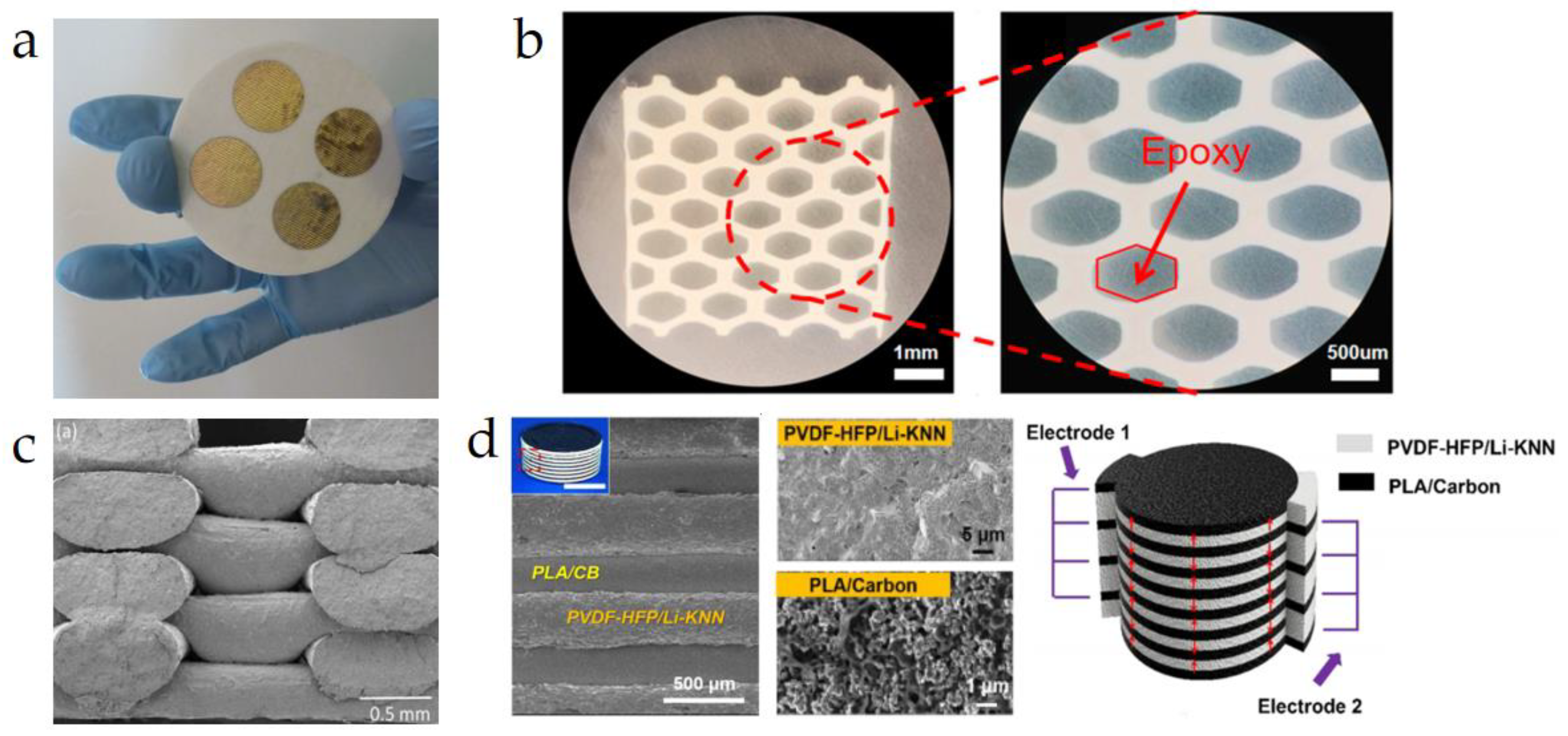
3.1.4. Dice-Fill
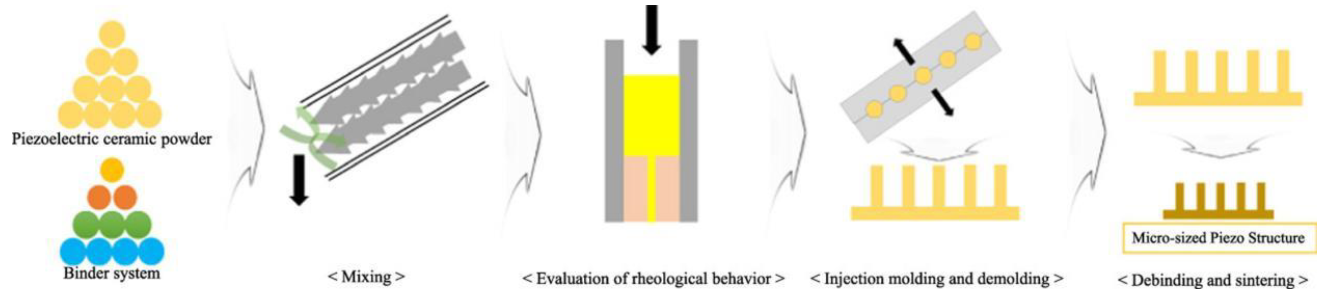
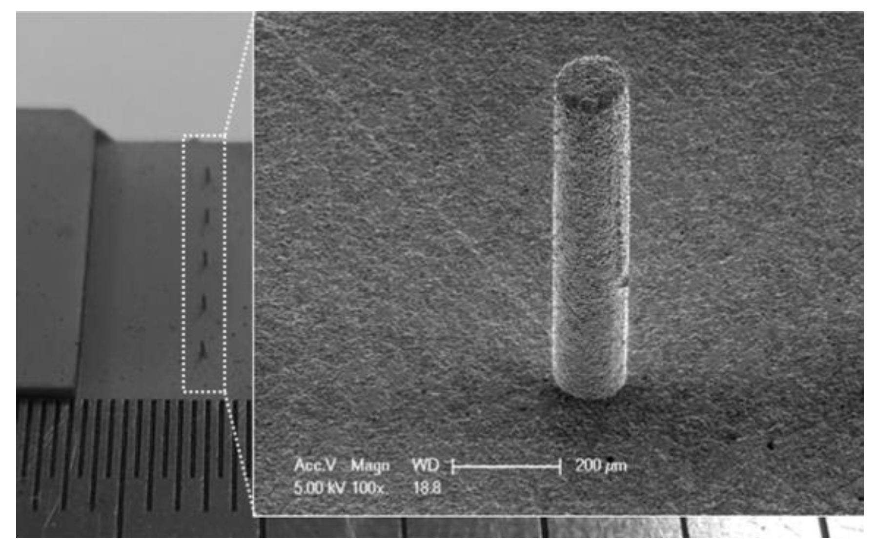
3.1.5. Injection-Molding
3.1.6. Freeze-Casting
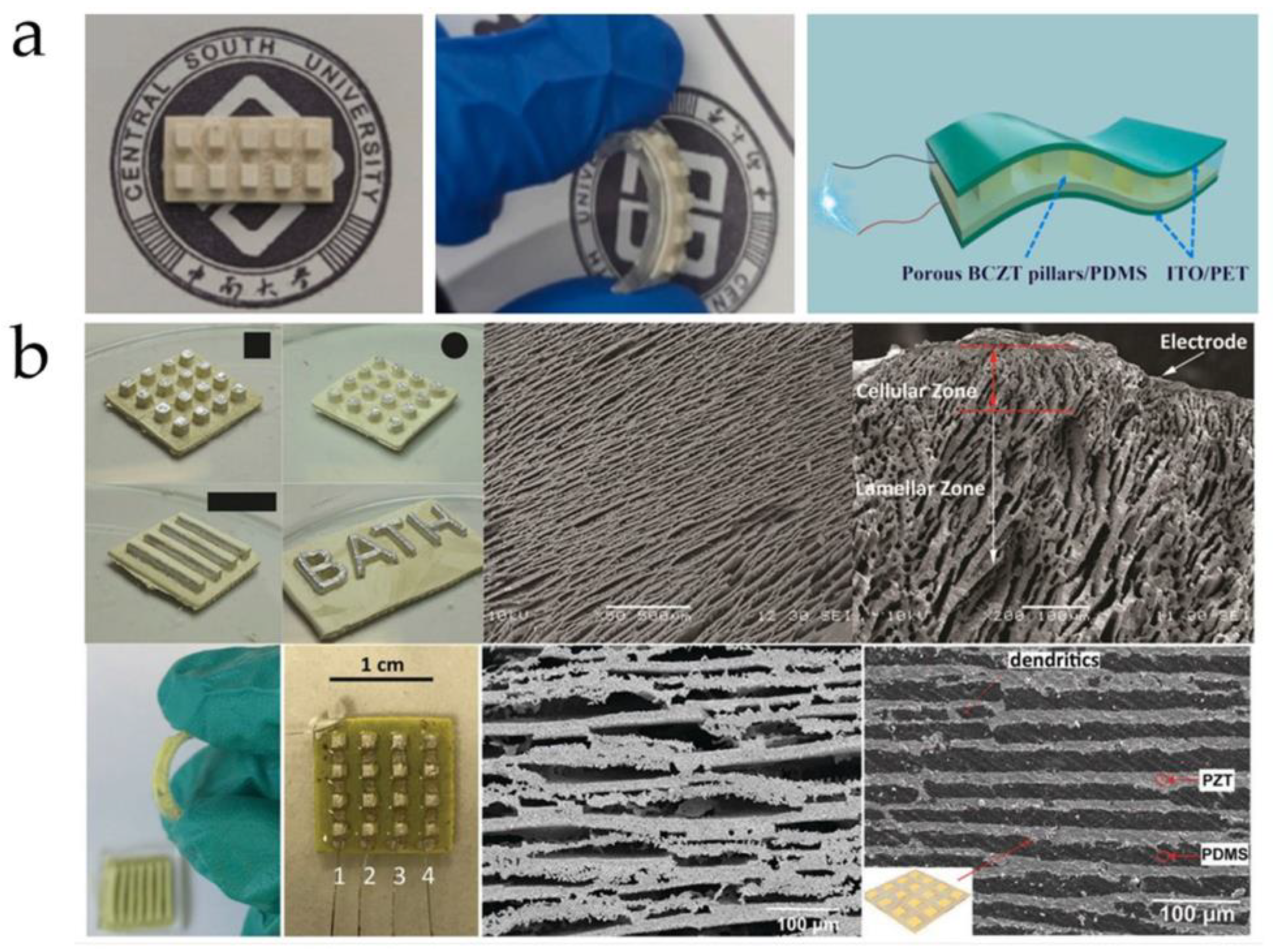
3.1.7. 3D Printing
3.2. Discussion on Factors Affecting the Piezoelectric Performance of Flexible Composite Materials
- (1)
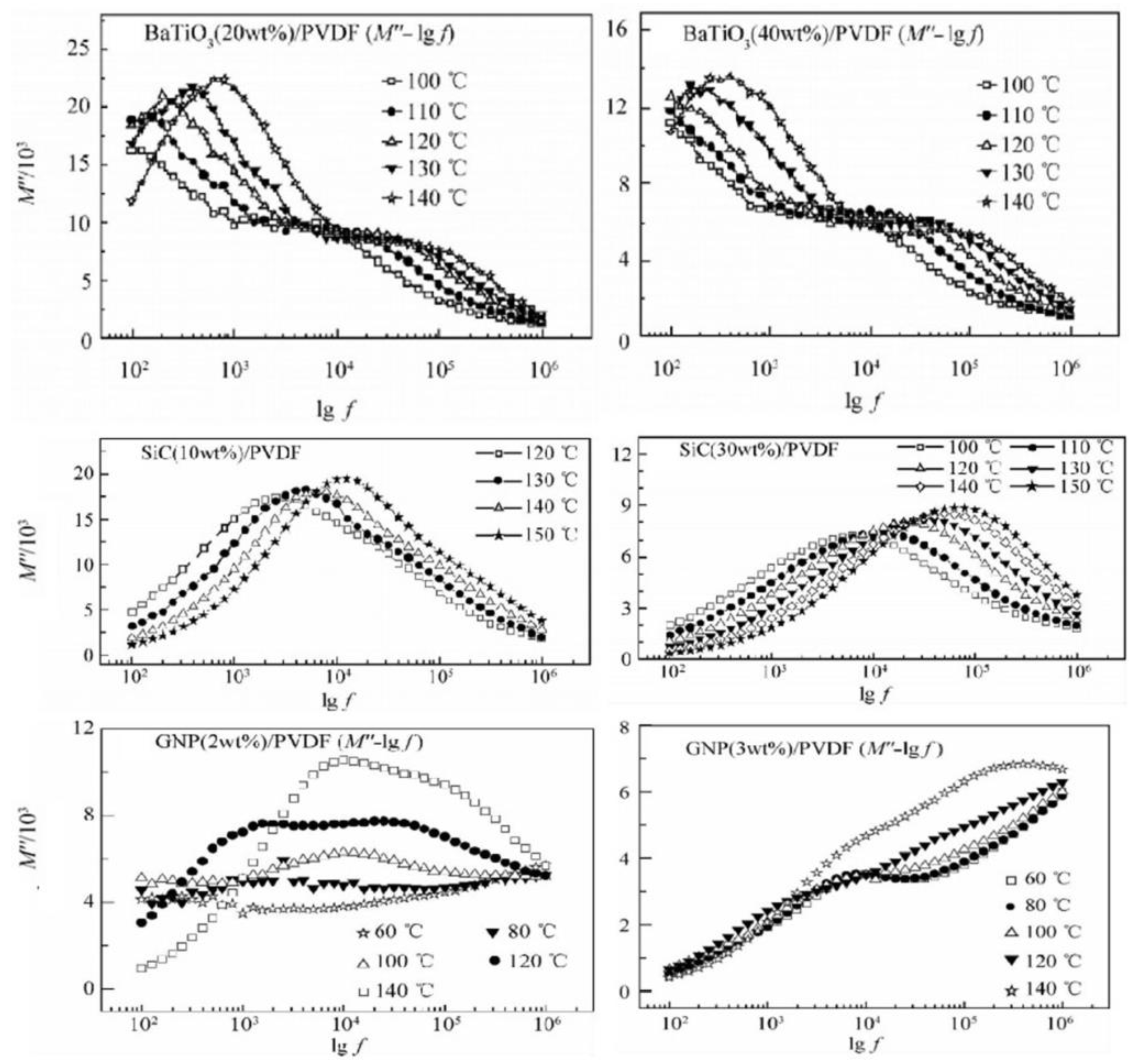
- Dielectric Relaxation Behavior
- (2)
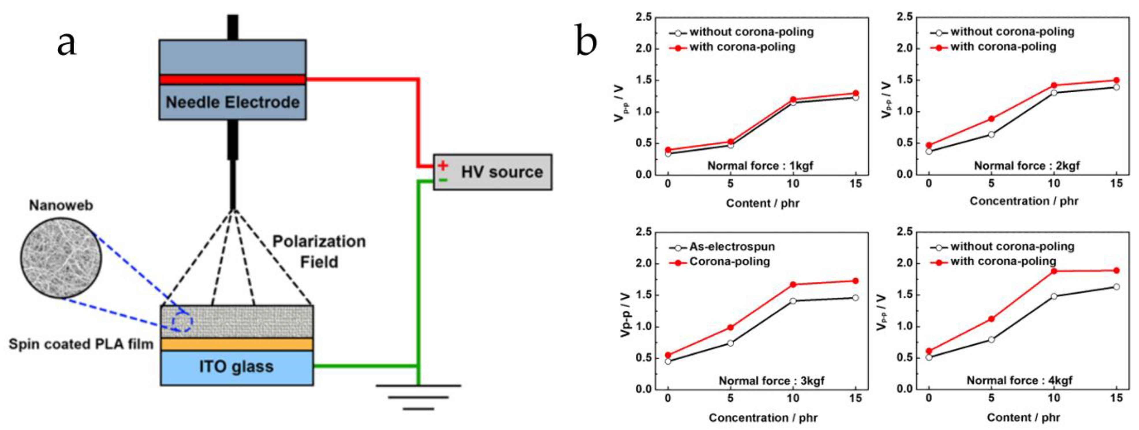
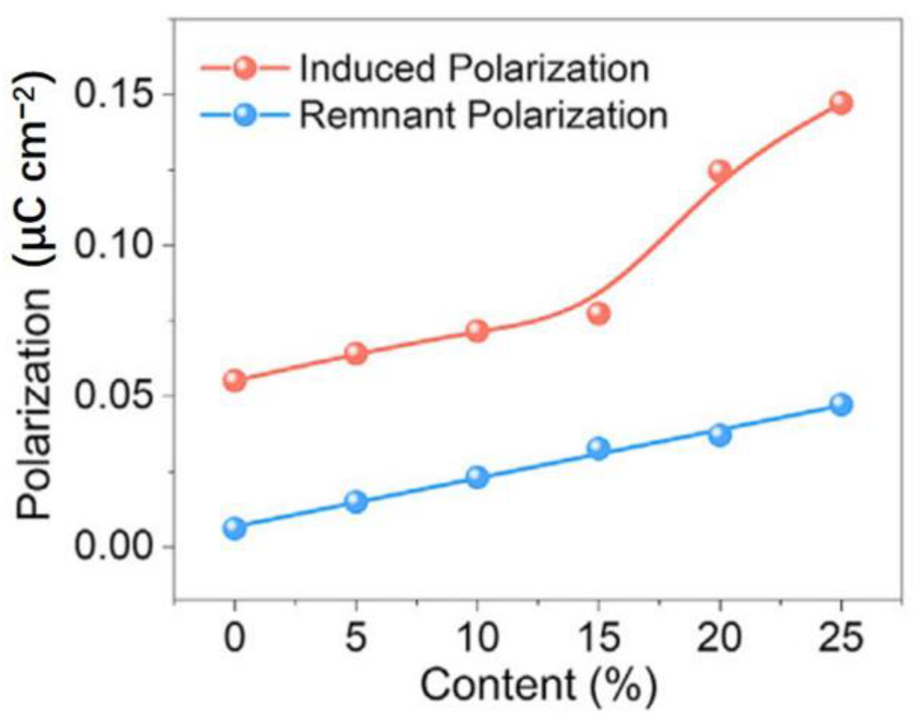
- Polarization
- (3)
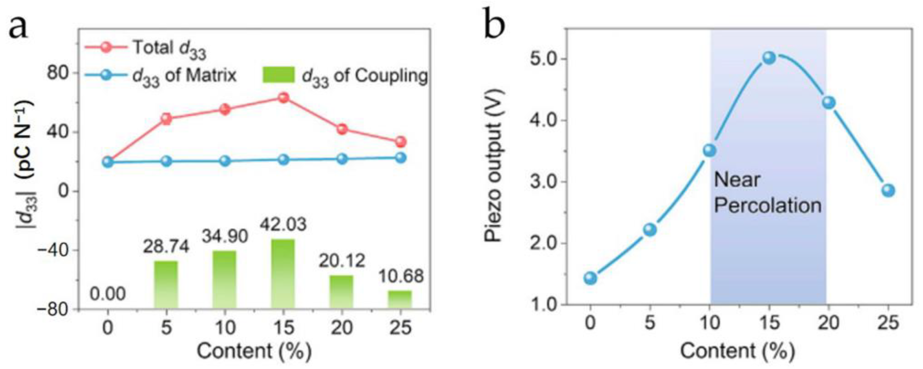
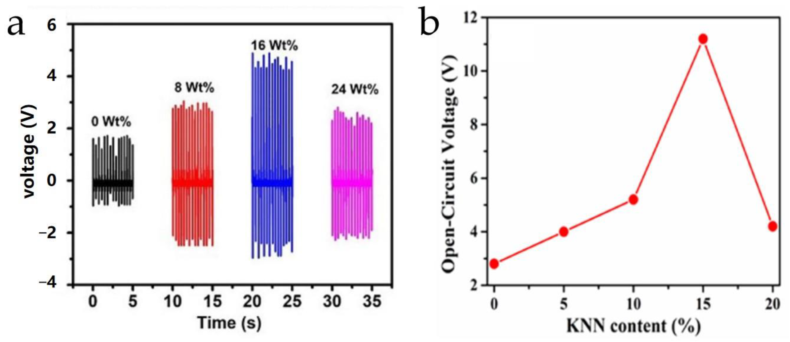
- Determination of Filler Content
- (4)
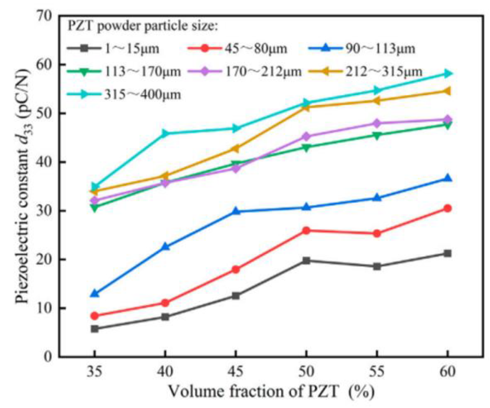
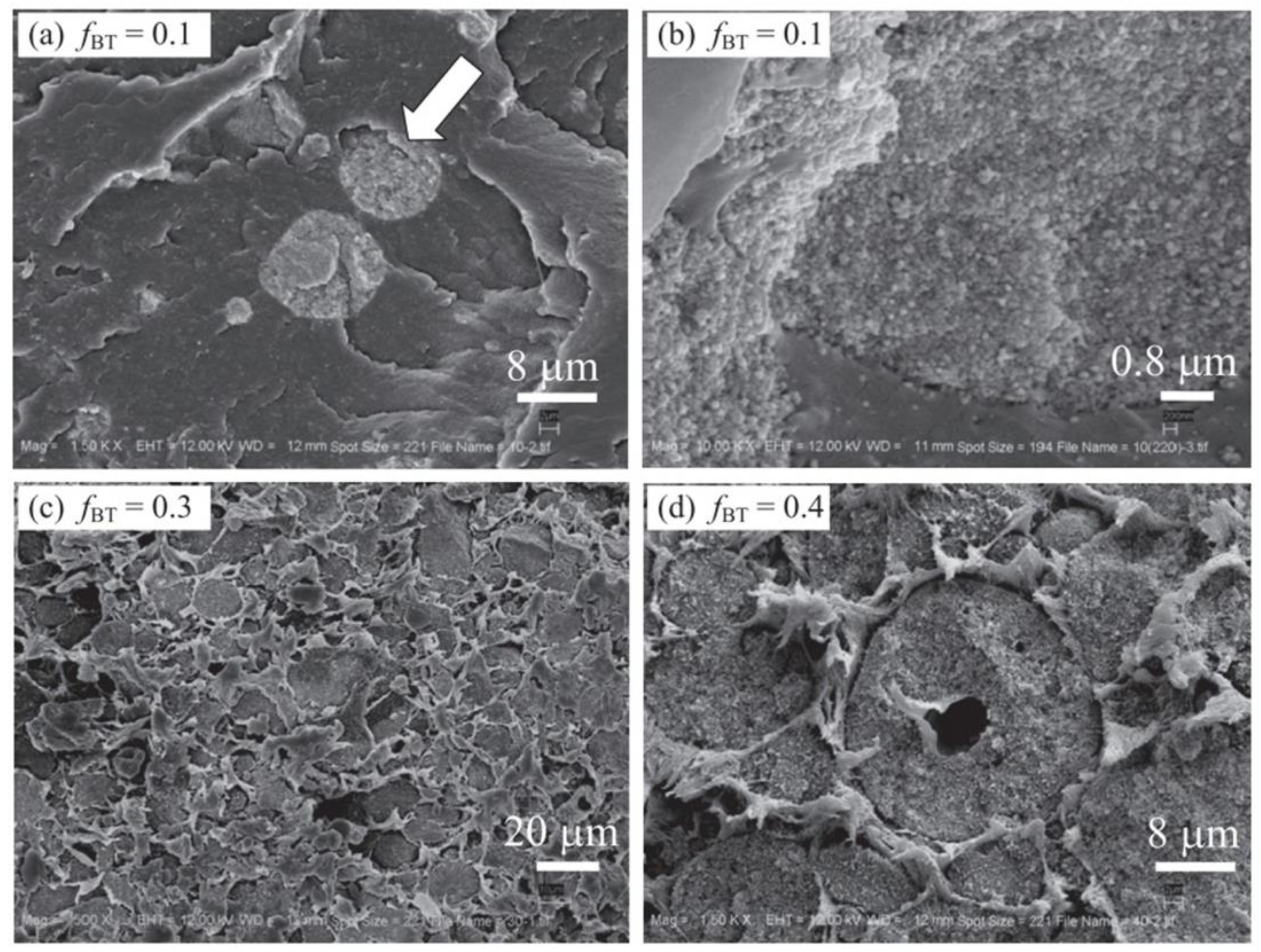
- Agglomeration
4. Application of Flexible Piezoelectric Composite Materials
4.1. Underwater Detection
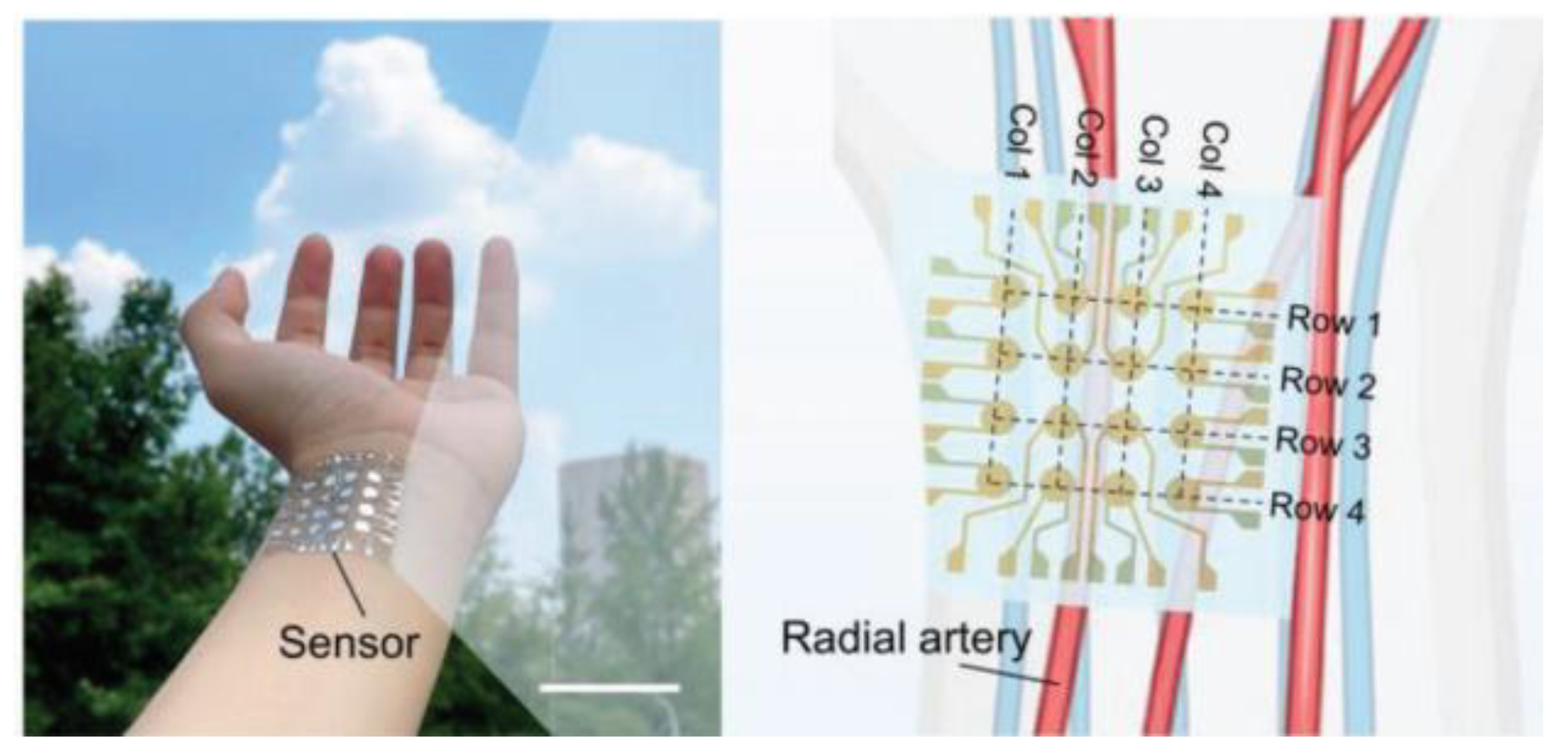
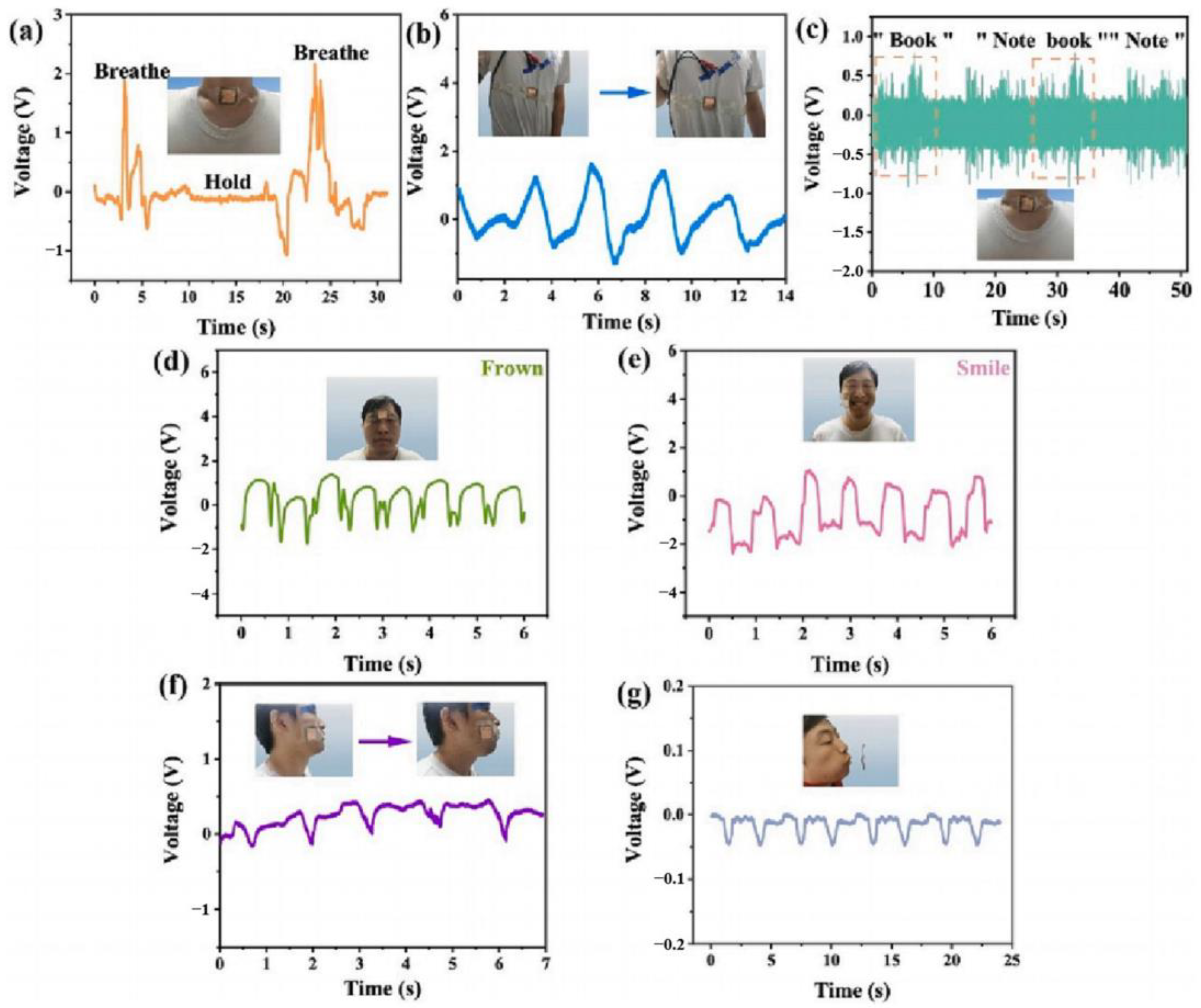
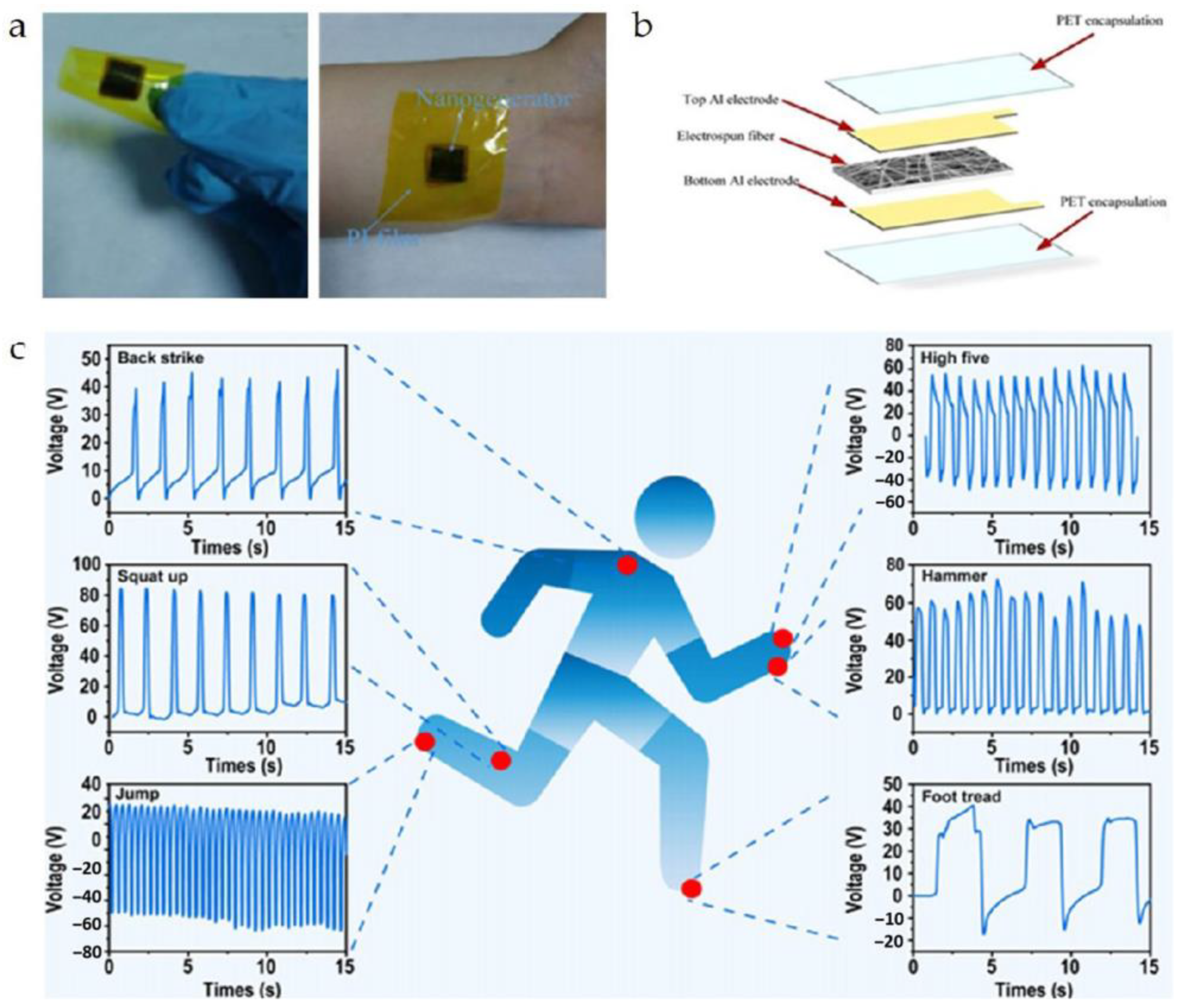
4.2. Wearable Sensor
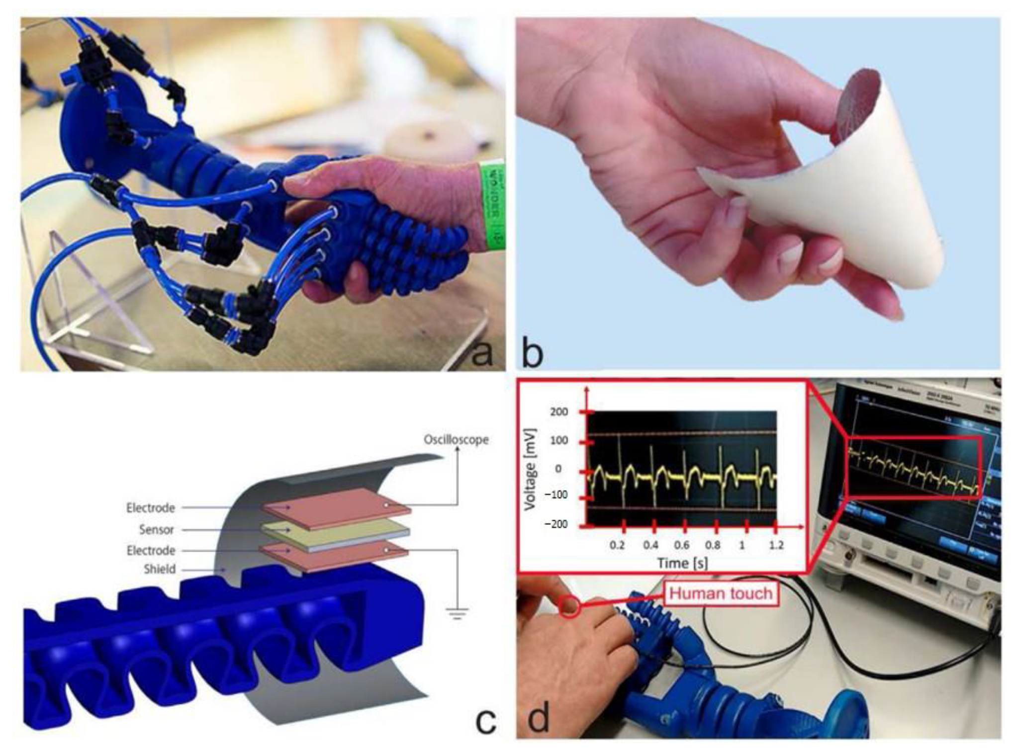
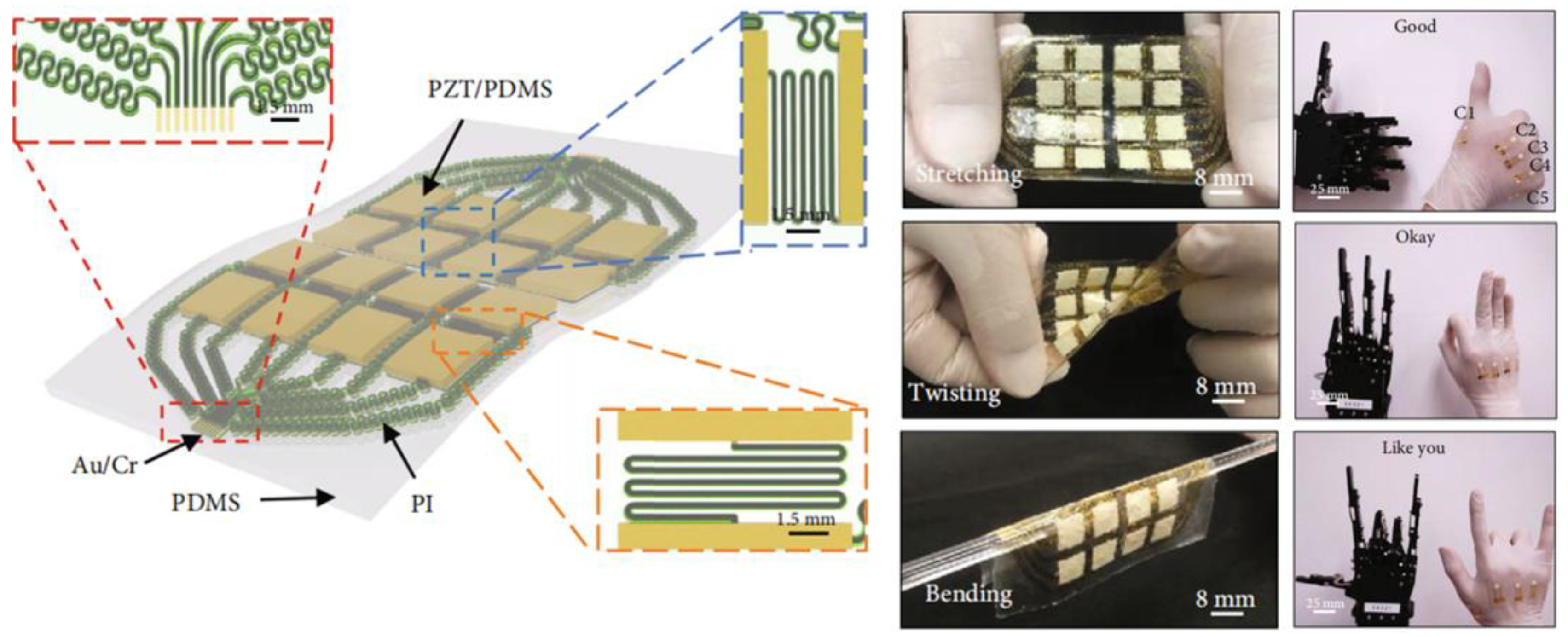
4.3. Flexible Electronic Skin
4.4. Targeted Therapy
4.5. Ultrasound Diagnostics for Deep Tissue
5. Conclusions and Outlook
- One critical aspect is non-toxicity and environmental sustainability. The enhancement of piezoelectric properties in flexible piezoelectric composite materials often involves doping with high lead content PZT powder, which is a ceramic material known for its high lead content, which poses potential harm to human health and the environment with prolonged use. Besides PZT, improved ZnO materials are occasionally considered for flexible piezoelectric composite materials. However, due to their toxic and polluting nature, these inherent drawbacks may limit the potential applications of such materials. Therefore, advancements in non-toxic and environmentally friendly piezoelectric materials have the potential to further expand the application scope of flexible piezoelectric composite materials. Furthermore, some researchers have integrated lead-free ceramics like BZT into applications involving piezoelectric composite materials, suggesting that flexible piezoelectric composite materials developed using such piezoelectric materials may hold significant economic advantages.
- Functional integration of sensing structures. The inception of wearable sensors and electronic skin has initiated a new epoch in advancing the design of flexible piezoelectric composite materials towards miniaturization, convenience, and mass accessibility. However, many of these sensors are designed with relatively single functions, making it difficult to address complex integrated problems. For this reason, flexible piezoelectric composite materials may require smaller structural sizes to promote the multi-functional integration of sensors.
- Further optimization of performance trade-offs is essential. The development of flexible piezoelectric composite materials with high-performance trade-offs is crucial for resolving various trade-offs. For example, in 0-3 type piezoelectric composite materials, it is crucial to consider the balance between material flexibility and piezoelectricity. When the piezoelectric ceramic powder is excessively doped, the material’s flexibility will significantly decrease, while when the doping amount is too small, the material’s piezoelectricity will be greatly compromised. However, piezoelectric composites developed through doping tend to exhibit lower piezoelectricity compared to existing piezoelectric ceramics. Therefore, to meet performance requirements, the development of flexible piezoelectric materials that can simultaneously balance flexibility and high piezoelectricity will become extremely important. On the other hand, multi-component flexible piezoelectric composites, comprising three or more materials, demonstrate great development potential. Since achieving compression resistance and flexibility simultaneously in the same material poses challenges, this multi-component design approach provides support for balancing compression resistance and flexibility. In complex underwater environments, this approach might be the most optimal solution.
Author Contributions
Funding
Conflicts of Interest
References
- Xie, F. Natural polymer starch-based materials for flexible electronic sensor development: A review of recent progress. Carbohydr. Polym. 2024, 337, 122116. [Google Scholar] [CrossRef] [PubMed]
- Liu, Y.; Yue, W.; Zhang, Z. Application of Sensor Technology in Manufacturing Automation. Mech. Eng. Autom. 2023, 4, 162–164. [Google Scholar]
- Sawane, M.; Prasad, M. MEMS piezoelectric sensor for self-powered devices: A review. Mater. Sci. Semicond. Process. 2023, 158, 107324. [Google Scholar] [CrossRef]
- Zhang, Y. Research on High Frequency Spherical Broadband Transducer. Ph.D. Thesis, Beijing University of Posts and Telecommunications, Beijing, China, May 2022. [Google Scholar]
- Berto, L.; Ettmayer, J.; Stutzer, D.; Nietzsche, S.; Niederhauser, T.; Burger, J.; Sculean, A.; Eick, S.; Hofmann, M. In-vitro effects of novel periodontal scalers with a planar ultrasonic piezoelectric transducer on periodontal biofilm removal, dentine surface roughness, and periodontal ligament fibroblasts adhesion. Clin. Oral Investig. 2024, 28, 294. [Google Scholar] [CrossRef]
- Zhong, C.; Xu, J.; Hao, S.; Zhang, Y.; Wang, L.; Qin, L. High-frequency wide beam underwater transducer based on 1–3 piezocomposite. Ferroelectr. Lett. Sect. 2021, 48, 93–103. [Google Scholar] [CrossRef]
- Zhao, H.; Li, H.; Wang, Y.; Liu, Z.; Bian, J.; Chen, J. A thickness-mode high-frequency underwater acoustic transducer with a low sidelobe level. Actuators 2021, 10, 226. [Google Scholar] [CrossRef]
- Li, J.; Gao, Y.; Zhou, Z.; Ping, Q.; Qiu, L.; Lou, L. An AlScN Piezoelectric Micromechanical Ultrasonic Transducer-Based Power-Harvesting Device for Wireless Power Transmission. Micromachines 2024, 15, 624. [Google Scholar] [CrossRef]
- Singh, A.; Singh, M. Electrochemical and piezoelectric monitoring of taurine via electropolymerized molecularly imprinted films. J. Mol. Recognit. 2017, 30, e2652. [Google Scholar] [CrossRef]
- Yein, T.; Wang, Q.; Kim, S. Piezoelectric catalytic driven advanced oxidation process using two-dimensional metal dichalcogenides for wastewater pollutants remediation. Chemosphere 2024, 353, 141524. [Google Scholar] [CrossRef]
- Shi, X.; Sun, Y.; Tian, H.; Liu, H.; Li, D. 3D-printed wearable BaTiO3/PDMS piezoelectric nanogenerator for self-powered body movement sensing. Flex. Print. Electron. 2023, 8, 045005. [Google Scholar] [CrossRef]
- Hasan, M.; Rahman, M.; Sadeque, M.; Ordu, M. Self-Poled Piezoelectric Nanocomposite Fiber Sensors for Wireless Monitoring of Physiological Signals. ACS Appl. Mater. Interfaces 2024, 16, 34549–34560. [Google Scholar]
- Zhong, C. Research on Three-Phase Piezocomposite and Curved Surface Transducer. Ph.D. Thesis, Beijing University of Posts and Telecommunications, Beijing, China, April 2019. [Google Scholar]
- Luan, G.; Zhang, J.; Wang, R. Piezoelectric Transducers and Arrays; Beijing University: Beijing, China, 2005; pp. 73–100. [Google Scholar]
- Li, L. Research on 1–3 Series Piezoelectric Composite and Underwater Transducer. Ph.D. Thesis, Beijing University of Posts and Telecommunications, Beijing, China, May 2008. [Google Scholar]
- Newnham, R.; Bowen, L.; Klicker, K.; Cross, L. Composite piezoelectric transducers. Mater. Des. 1980, 2, 93–106. [Google Scholar] [CrossRef]
- Moulin, E.; Assaad, J.; Delebarre, C.; Kaczmarek, H.; Balageas, D. Piezoelectric transducer embedded in a composite plate: Application to Lamb wave generation. J. Appl. Phys. 1997, 82, 2049–2055. [Google Scholar] [CrossRef]
- Shi, Y. Structural Design and Performance Analysis of a Flexible Piezoresistive Pressure Sensor. Master’s Thesis, Xi’an University of Technology, Xi’an, China, June 2023. [Google Scholar]
- Wen, D. The Preparation and Application of Magnetoelectrical Composite Materials. Ph.D. Thesis, University of Electronic Science and Technology of China, Chengdu, China, June 2018. [Google Scholar]
- Teng, D.; Yang, H.; Li, D. Fundamentals of Underwater Acoustic Transducers; Northwestern Polytechnical University: Xi’an, China, 2016; pp. 21–26. [Google Scholar]
- Nurkowski, J.; Nowakowski, A. Inductive sensor for measuring linear displacement and velocity-Version with stationary magnetic core. Measurement 2023, 222, 113675. [Google Scholar] [CrossRef]
- Xiao, Z. Structure Design and Electrical Output Performance of Flexible Piezoelectric Composites. Master’s Thesis, Central South University, Changsha, China, June 2023. [Google Scholar]
- Xu, L. Study on Fabrication, Structure and Peoperties of PZT5/Epoxy Resin 1–3 Composite. Ph.D. Thesis, Wuhan University of Technology, Wuhan, China, May 2006. [Google Scholar]
- Wang, H. Analysis for the effective properties of piezocomposite. Master’s Thesis, Beijing University of Technology, Beijing, China, May 2006. [Google Scholar]
- Li, N. Study on Preparation and Physical Properties of 1–3 Piezoelectric Composites. Master’s Thesis, Shandong University, Jinan, China, 29 May 2019. [Google Scholar]
- Richard, C.; Eyraud, P.; Eyraud, L.; Audigier, D.; Richard, M. An optimization of 1.3.1 PZT-polymer composite for deep underwater hydrophone application. In Proceedings of the Eighth IEEE International Symposium on Applications of Ferroelectrics, Greenville, SC, USA, 30 August 1992; pp. 255–258. [Google Scholar]
- Howarth, T.; Ting, R. Development of a broadband underwater sound projector, Oceans’ 97. In Proceedings of the MTS/IEEE Conference Proceedings, Halifax, NS, Canada, 6–9 October 1997; pp. 1195–1201. [Google Scholar]
- Benjamin, K. Recent advances in 1–3 piezoelectric polymer composite transducer technology for AUV/UUV acoustic imaging applications. J. Electroceramics 2002, 8, 145–154. [Google Scholar] [CrossRef]
- Bowen, L.; Gentilman, R.; Fiore, D.; Hong, P.; Serwatka, W.; Near, C.; Pazol, B. Design, fabrication, and properties of sonopanelTM 1–3 piezocomposite transducers. Ferroelectrics 1996, 187, 109–120. [Google Scholar] [CrossRef]
- Howarth, T.; Ting, R. Electroacoustic evaluations of 1–3 piezocomposite SonoPanelTM materials. IEEE Trans. Ultrason. Ferroelectr. Freq. Control 2000, 47, 886–894. [Google Scholar] [CrossRef] [PubMed]
- Robertson, D.; Cochran, S. Experimental investigation of alternative pre-stress components for a 3–1 connectivity multilayer piezoelectric-polymer composite ultrasonic transducer. Ultrasonics 2002, 40, 913–919. [Google Scholar] [CrossRef] [PubMed]
- Pei, L.; Roh, Y. Design of an Underwater Tonpilz Transducer with 1–3 Piezocomposite Materials. Jpn. J. Appl. Phys. 2008, 47, 4003–4006. [Google Scholar] [CrossRef]
- Li, L.; Wang, L.; Qin, L.; Wang, G. Modified 1–3 Ceramic/Epoxy Piezocompsite and Cylinder Array Transducer. Ferroelectrics 2010, 409, 145–151. [Google Scholar] [CrossRef]
- Benjamin, K.; Petrie, S. A new Navy calibration standard transducer using 1–3 piezocomposite. In Proceedings of the OCEANS 2000 MTS/IEEE Conference and Exhibition, Providence, RI, USA, 11–14 September 2000; pp. 1299–1304. [Google Scholar]
- Safari, A.; Danforth, S.; Panda, R.; Lous, G.; Cornejo, I.; Kholkine, A. Novel piezocomposites for ultrasonic transducer applications. In Proceedings of the 1998 IEEE Ultrasonics Symposium, Sendai, Japan, 5–8 October 1998; Volume 1, pp. 615–618. [Google Scholar]
- Cochran, A.; Reynolds, P.; Hayward, G. Progress in stacked piezocomposite ultrasonic transducers for low frequency applications. Ultrasonics 1998, 36, 969–977. [Google Scholar] [CrossRef]
- Ritter, T.; Shrout, T.; Tutwiler, R.; Shuang, K. A 30-MHz piezo-composite ultrasound array for medical imaging applications. IEEE Trans. Ultrason. Ferroelectr. Freq. Control 2002, 49, 217–230. [Google Scholar] [CrossRef]
- Fleury, G.; de Lima, D.; Hynynen, K.; Berriet, R.; Baron, O.; Huguenin, B. New piezocomposite transducers for therapeutic ultrasound. In Proceedings of the Thermal Treatment of Tissue: Energy Delivery and Assessment II, San Jose, CA, USA, 10 June 2003; Volume 4954, pp. 227–236. [Google Scholar]
- Or, S.; Chan, H.; Liu, P. Piezocomposite ultrasonic transducer for high-frequency wire-bonding of microelectronics devices. Sens. Actuators A Phys. 2007, 133, 195–199. [Google Scholar] [CrossRef]
- Zhang, Q.; Chen, J.; Wang, H.; Zhao, J.; Cross, L.; Trottier, M. A new transverse piezoelectric mode 2–2 piezocomposite for underwater transducer applications. IEEE Trans. Ultrason. Ferroelectr. Freq. Control 1995, 42, 774–781. [Google Scholar] [CrossRef]
- Yoon, K.; Shin, S.; Park, H.; Goo, N. Design and manufacture of a lightweight piezo-composite curved actuator. Smart Mater. Struct. 2002, 11, 163. [Google Scholar] [CrossRef]
- Schoenecker, A.; Gebhardt, S.; Roedig, T.; Keitel, U.; Brueckner, B.; Schnetter, J.; Daue, T. Piezocomposite transducers for smart structures applications. In Proceedings of the Smart Structures and Materials 2005: Smart Structures and Integrated Systems, San Diego, CA, USA, 17 May 2005; Volume 5764, pp. 34–41. [Google Scholar]
- Schultz, M.; Hyer, M.; Williams, R.; Wilkie, W.; Inman, D. Snap-through of unsymmetric laminates using piezocomposite actuators. Compos. Sci. Technol. 2006, 66, 2442–2448. [Google Scholar] [CrossRef]
- Salas, K.; Cesnik, C.; Raghavan, A. Modeling of wedge-shaped anisotropic piezocomposite transducer for guided wave-based structural health monitoring. In Proceedings of the 48th AIAA/ASME/ASCE/AHS/ASC Structures, Structural Dynamics, and Materials Conference, Honolulu, Hawaii, 23–26 April 2007; p. 1723. [Google Scholar]
- Gentilman, R.; Bowen, L.; Fiore, D.; Pham, H.; Serwatka, W. Injection molded 1–3 piezocomposite velocity sensors. In Proceedings of the AIP Conference Proceedings, Mystic, CT, USA, 12–13 September 1995; Volume 368, pp. 312–319. [Google Scholar]
- Yuan, Y. Measuring frozen soils with composite piezoelectric transducers of 1–3 and 2–2 connectivity. J. Appl. Acoust. 2003, 22, 39–44. [Google Scholar]
- Badcock, R.; Birt, E. The use of 0–3 piezocomposite embedded Lamb wave sensors for detection of damage in advanced fibre composites. Smart Mater. Struct. 2000, 9, 291. [Google Scholar] [CrossRef]
- Kim, C.; Rittenmyer, K.; Kahn, M. 1–1–3 Piezocomposite for hydrophone transducer. Ferroelectrics 1994, 156, 19–24. [Google Scholar] [CrossRef]
- Wang, L.; Wan, Y.; Li, L.; Qin, L.; Lu, Y. Investigation on stability of PZT/epoxy piezocomposite with pressure and temperature. Acta Mech. Solida Sin. 2009, 22, 226–231. [Google Scholar] [CrossRef]
- Qin, L.; Li, L.; Wang, L.; Sun, B. Research on Hydrostatic Characteristics of 3–2 Piezoelectric Composite. J. Funct. Mater. 2007, 11, 1824–1830. [Google Scholar]
- Li, L.; Wang, L.; Qin, L.; Lv, Y. The theoretical model of 1–3–2 piezocomposites. IEEE Trans. Ultrason. Ferroelectr. Freq. Control 2009, 56, 1476–1482. [Google Scholar] [CrossRef] [PubMed]
- Cheng, X.; Xu, D.; Lu, L.; Huang, S.; Jiang, M. Performance investigation of 1–3 piezoelectric ceramic-cement composite. Mater. Chem. Phys. 2010, 121, 63–69. [Google Scholar] [CrossRef]
- Potong, R.; Rianyoi, R.; Jaitanong, N.; Yimnirun, R.; Chaipanich, A. Ferroelectric hysteresis behavior and dielectric properties of 1–3 lead zirconate titanate–cement composites. Ceram. Int. 2011, 38, S267–S270. [Google Scholar] [CrossRef]
- Hu, R.; Li, J.; Wu, F.; Lu, Z.; Deng, C. A dual function flexible sensor for independent temperature and pressure sensing. Chem. Eng. J. 2024, 491, 152135. [Google Scholar] [CrossRef]
- Sun, Y.; Yang, Y.; Yao, D.; Gao, X.; Chen, J.; Wang, H.; You, T.; Dong, Y.; Lu, Y.; Lu, C.; et al. Biomimetic multilayer flexible sensors for multifunctional underwater sensing. Chem. Eng. J. 2024, 492, 152273. [Google Scholar] [CrossRef]
- Dong, Y.; Xu, C.; Chen, S.; Wang, Z. Flexible piezoelectric pressure sensor based on BaTiO3–CNT/RTV composite film with filter paper microstructures for monitoring hand motions. Meas. Sci. Technol. 2024, 35, 085111. [Google Scholar] [CrossRef]
- Zhang, C.; Yuan, C.; Zhu, Q.; Sun, H. Large-scale fabrication and performance improvement of polyvinylidene fluoride piezoelectric composite films. Ceram. Int. 2023, 49, 27255–27265. [Google Scholar] [CrossRef]
- Wei, X.; Xu, K.; Wang, Y.; Zhang, Z.; Chen, Z. 3D Printing of Flexible BaTiO3/Polydimethylsiloxane Piezocomposite with Aligned Particles for Enhanced Energy Harvesting. ACS Appl. Mater. Interfaces 2024, 16, 11740–11748. [Google Scholar] [CrossRef]
- Zhao, Z.; Yu, Y.; He, L.; Wang, Z.; Kurita, H.; Narita, F. Effect of carbon black addition on electromechanical performance of flexible piezoelectric composite films. Compos. Part A 2024, 180, 108103. [Google Scholar] [CrossRef]
- Verma, K.; Sharma, R. Development of KNNLTS-PVDF-based flexible piezoelectric generator for energy-harvesting application. Bull. Mater. Sci. 2024, 47, 38. [Google Scholar] [CrossRef]
- Huang, Z.; Li, L.; Huang, Y.; Rao, W.; Jiang, H.; Wang, J.; Zhang, H.; He, H.; Qu, J. Self-poled piezoelectric polymer composites via melt-state energy implantation. Nat. Commun. 2024, 15, 819. [Google Scholar] [CrossRef] [PubMed]
- Jiang, S.; Shen, Y.; Wang, S.; Jiang, W.; Liu, Y.; Wu, Q. Flexible piezoelectric composite sensor for impact monitoring of curved structures. Sens. Actuators A Phys. 2023, 362, 114655. [Google Scholar] [CrossRef]
- Chen, S.; Luo, J.; Wang, X.; Li, Q.; Zhou, L.; Liu, C.; Feng, C. Fabrication and piezoresistive/piezoelectric sensing characteristics of carbon nanotube/PVA/nano-ZnO flexible composite. Sci. Rep. 2020, 10, 8895. [Google Scholar] [CrossRef] [PubMed]
- Suyambazhahan, S.; Rao, C.; Girma, D. Characterization of 0–3 piezoelectric polymer composites using FEA for biomedical transducers applications. Ferroelectrics 2024, 618, 718–731. [Google Scholar] [CrossRef]
- Guler, Z.; Vazquez, I.; Jackson, N. Multi-functional 0–3 composite polyimide films for microsystem applications. Smart Mater. Struct. 2023, 32, 075015. [Google Scholar] [CrossRef]
- Wang, L.; Wang, K.; Shi, S.; Wang, N.; Zhang, L.; Lu, B. 3D printed 0–3 type piezoelectric composites with high voltage sensitivity-. Ceram. Int. 2022, 48, 12559–12568. [Google Scholar] [CrossRef]
- Weng, F. Design, Fabrication and Application of Flexible Pressure Sensor Based on PVDF Piezoelectric Film. Master’s Thesis, Hangzhou Dianzi University, Hangzhou, China, May 2023. [Google Scholar]
- He, S. Preparation and Performance Study of PVDF Blended Composite Film and Its Application in Sensor. Master’s Thesis, Beijing Institute of Petrochemical Technology, Beijing, China, June 2023. [Google Scholar]
- Li, Y.; Xu, L.; Wang, L.; Zhang, B.; Wang, P. Performance optimization of piezoelectric PVDF film and its application. New Chem. Mater. 2023, 51, 8–12. [Google Scholar]
- Ali, N.; Kenawy, E.; Wadoud, A.; Elhadary, M. Wearable Electrospun Piezoelectric Mats Based on a PVDF Nanofiber–ZnO@ ZnS Core–Shell Nanoparticles Composite for Power Generation. Nanomaterials 2023, 13, 2833. [Google Scholar] [CrossRef]
- Taleb, S.; Badillo, M.; Flores-Ruiz, F.; Acuautla, M. From synthesis to application: High-quality flexible piezoelectric sensors fabricated from tetragonal BaTiO3/P(VDF-TrFE) composites. Sens. Actuators A Phys. 2023, 361, 114585. [Google Scholar] [CrossRef]
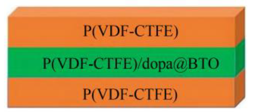
- Xiong, P.; Wu, R.; Ma, C.; Xu, J.; Wang, Q. Study on dielectric and energy storage characteristics of P(VDF-CTFE/dopa@BTO laminated composite film. Insul. Mater. 2024, 54, 28–35. [Google Scholar]
- He, S.; Xue, R.; He, Y.; Huang, Y.; Wu, Y.; Shi, Q. Preparation and Properties of Tb3+ Doped PVDF/PLLA Electrospun Multifunctional Piezoelectric Nano fibers. Mater. Rep. 2024, 38, 250–255. [Google Scholar]
- Jiang, S.; Shen, Y.; Wang, S.; Zhi, Y.; Han, B. Properties of novel 0–3 PZT/silicone resin flexible piezoelectric composites for ultrasonic guided wave sensor applications. Front. Mater. 2022, 9, 958775. [Google Scholar] [CrossRef]
- Bradley, L.; Yaras, Y.; Karahasanoglu, B.; Atasoy, B.; Degertekin, F. Application of low-temperature processed 0–3 composite piezoelectric thick films in flexible, nonplanar, high-frequency ultrasonic devices. IEEE Sens. J. 2023, 23, 6672–6679. [Google Scholar] [CrossRef]
- Jo, E.; Lee, Y.; Cho, Y.; Gunther, P.; Gebhardt, S.; Neubert, H.; Kim, H. The 0–3 Lead Zirconate-Titanate (PZT)/Polyvinyl-Butyral (PVB) Composite for Tactile Sensing. Sensors 2023, 23, 1649. [Google Scholar] [CrossRef]
- Zhang, J.; Wang, J.; Zhong, C.; Qin, L. 1–3-Type piezoelectric composites with three-layer cascade structure. Compos. Struct. 2023, 322, 117406. [Google Scholar] [CrossRef]
- Zhou, C.; Zhang, J.; Su, W.; Cao, Y. Large thickness-mode electromechanical coupling and good temperature stability of 1–3 PZT/epoxy composites. J. Mater. Sci. Mater. Electron. 2021, 32, 4705–4712. [Google Scholar] [CrossRef]
- Wang, J.; Chen, M.; Zhao, X.; Wang, F.; Tang, Y.; Lin, D.; Luo, H. Fabrication and high acoustic performance of high frequency needle ultrasound transducer with PMN-PT/Epoxy 1–3 piezoelectric composite prepared by dice and fill method. Sens. Actuators A Phys. 2021, 318, 112528. [Google Scholar] [CrossRef]
- Zhao, Y.; Wang, L.; Liao, Q. Temperature stability of hyperboloid piezoelectric composite. J. Beijing Inf. Sci. Technol. Univ. Sci. Technol. Ed. 2021, 36, 53–58. [Google Scholar]
- Huang, Q. Research on High Frequency and Broadband Directional Controllable Cylindrical Transducer. Master’s Thesis, Beijing Information Science and Technology University, Beijing, China, June 2021. [Google Scholar]
- Sim, M.; Jeong, W.; Hong, C. An equivalent circuit based electro-vibro-acoustic model of a cylindrical transducer array. J. Acoust. Soc. Am. 2021, 149, 3228–3240. [Google Scholar] [CrossRef]
- Herickhoff, C.; Telichko, A.; Dahl, J. Cylindrical transducer for intravascular ARFI imaging: Design and feasibility. IEEE Trans. Ultrason. Ferroelectr. Freq. Control 2019, 67, 760–769. [Google Scholar] [CrossRef] [PubMed]
- Kim, T.; Cui, Z.; Chang, W.; Kim, H.; Zhu, Y.; Jiang, X. Flexible 1–3 composite ultrasound transducers with silver-nanowire-based stretchable electrodes. IEEE Trans. Ind. Electron. 2019, 67, 6955–6962. [Google Scholar] [CrossRef]
- Hou, C.; Li, Z.; Fei, C.; Wang, Y.; Zhao, T.; Quan, Y.; Chen, D.; Li, X.; Bao, W.; Li, Y.; et al. Active acoustic field modulation of ultrasonic transducers with flexible composites. Commun. Phys. 2023, 6, 252. [Google Scholar] [CrossRef]
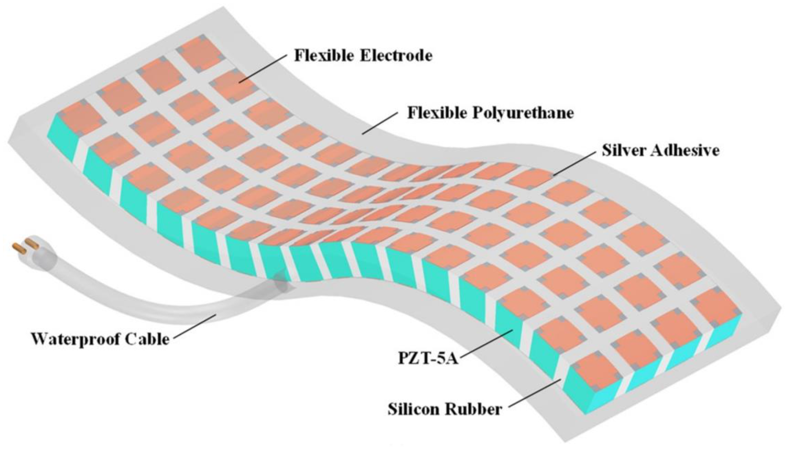
- Hao, S.; Zhong, C.; Wang, L.; Qin, L. A High-Performance Flexible Hydroacoustic Transducer Based on 1–3 PZT-5A/Silicone Rubber Composite. Sensors 2024, 24, 2081. [Google Scholar] [CrossRef] [PubMed]
- Hao, S.; Zhong, C.; Zhang, Y.; Chen, Y.; Wang, L.; Qin, L. Flexible 1–3 Piezoelectric Composites with Soft Embedded Conductive Interconnects for Underwater Acoustic Transducers. ACS Appl. Electron. Mater. 2023, 5, 2686–2695. [Google Scholar] [CrossRef]
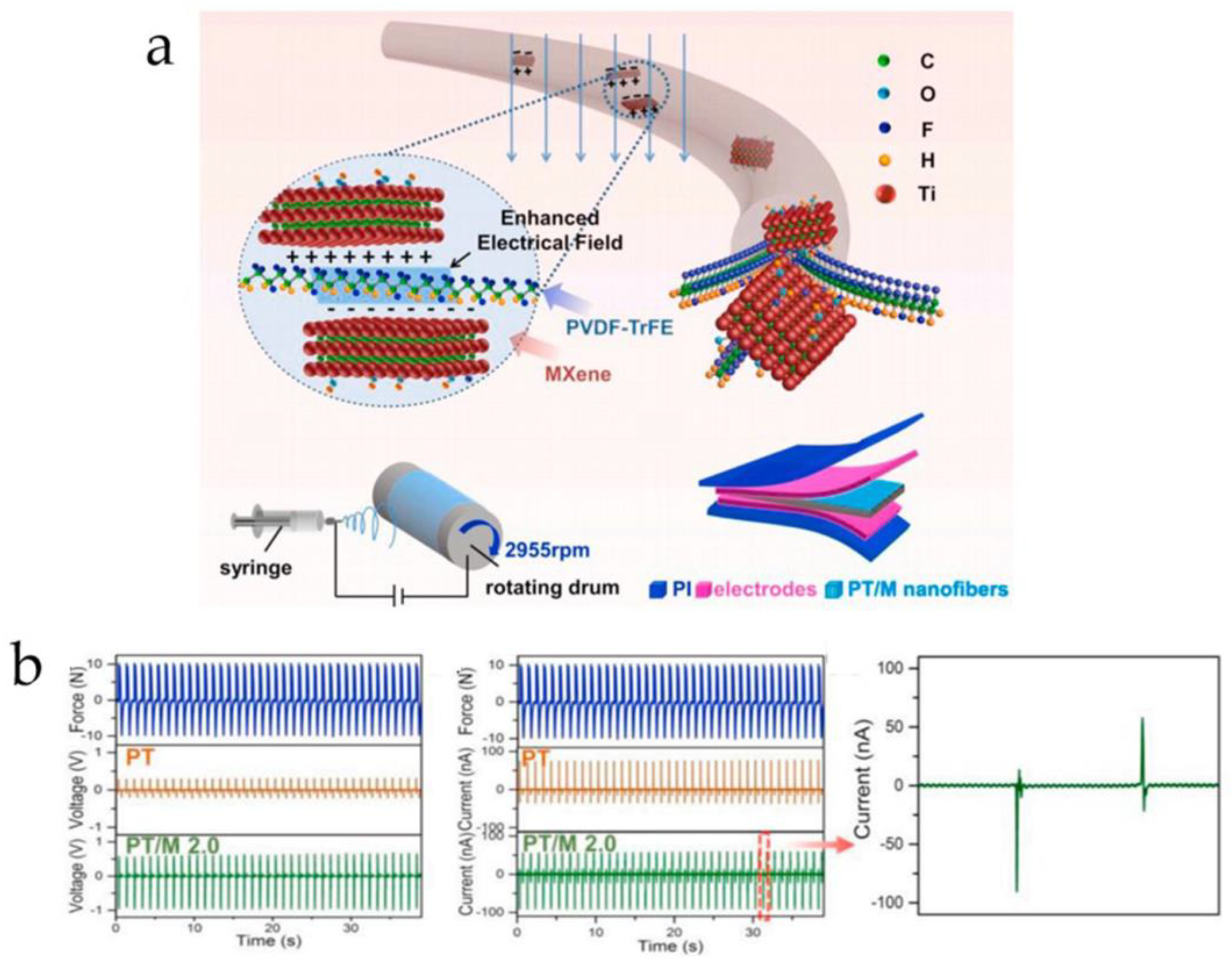
- Wang, S.; Shao, H.; Liu, Y.; Tang, C.; Zhao, X.; Ke, K.; Bao, R.; Yang, M.; Yang, W. Boosting piezoelectric response of PVDF-TrFE via MXene for self-powered linear pressure sensor. Compos. Sci. Technol. 2021, 202, 108600. [Google Scholar] [CrossRef]
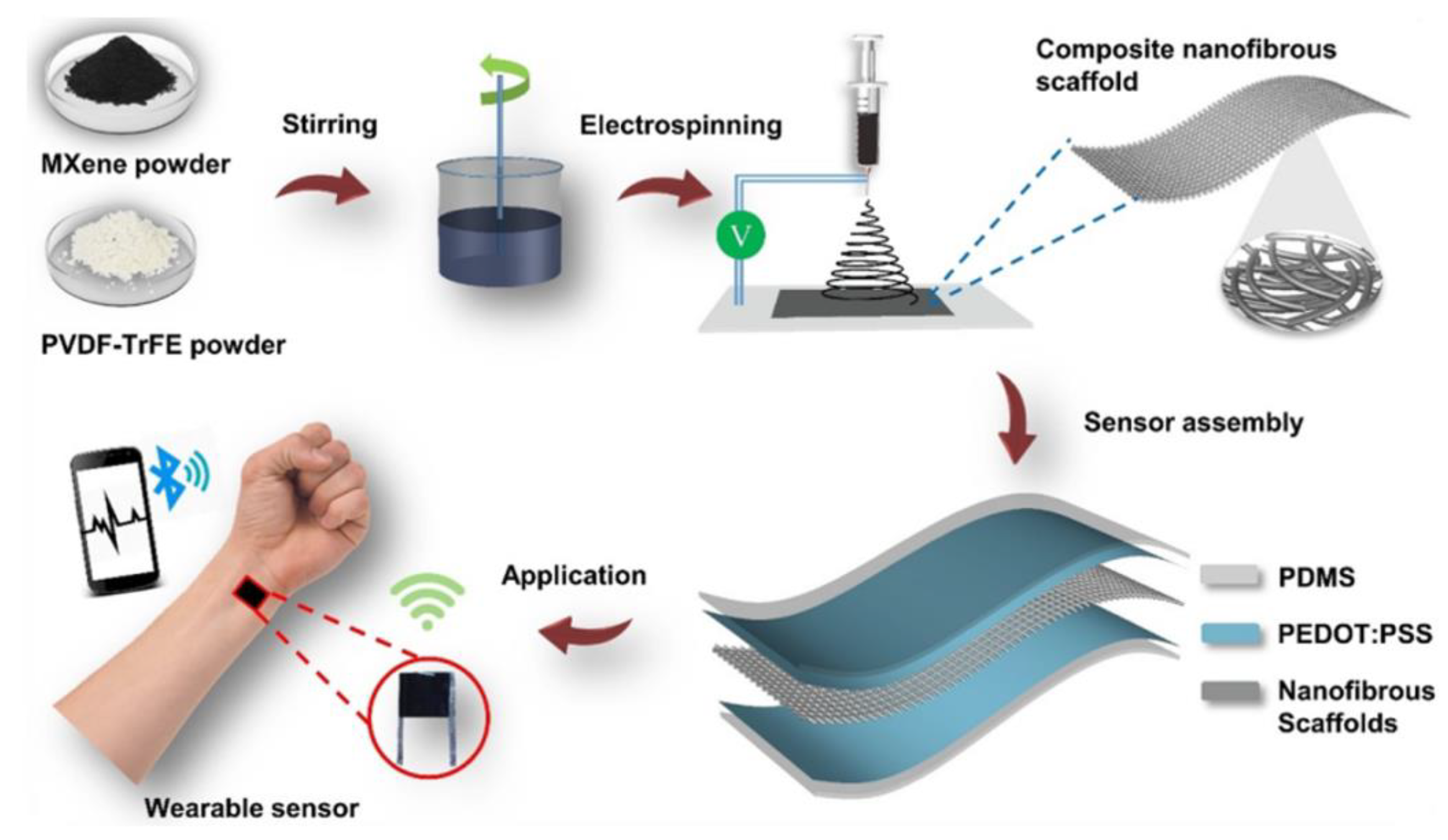
- Sharma, S.; Chhetry, A.; Sharifuzzaman, M.; Yoon, H.; Park, J. Wearable Capacitive Pressure Sensor Based on MXene Composite Nanofibrous Scaffolds for Reliable Human Physiological Signal Acquisition. ACS Appl. Mater. Interfaces 2020, 12, 22212–22224. [Google Scholar] [CrossRef] [PubMed]
- Bhavanasi, V.; Kumar, V.; Parida, K.; Wang, J.; Lee, P. Enhanced Piezoelectric Energy Harvesting Performance of Flexible PVDF-TrFE Bilayer Films with Graphene Oxide. ACS Appl. Mater. Interfaces 2016, 8, 521–529. [Google Scholar] [CrossRef]
- Qin, L. Mechanical and electrical coupling characteristics of 1–3 piezoelectric composite. J. Beijing Inf. Sci. Technol. Univ. Sci. Technol. Ed. 2018, 33, 1–6. [Google Scholar]
- Wang, J.; Zhong, C.; Hao, S.; Wang, L. Design and properties analysis of novel modified 1–3 piezoelectric composite. Materials 2021, 14, 1749. [Google Scholar] [CrossRef]
- Tang, T.; Shen, Z.; Wang, J.; Xu, S.; Jiang, J.; Chang, J.; Guo, M.; Fan, Y.; Xiao, Y.; Dong, Z.; et al. Stretchable polymer composites with ultrahigh piezoelectric performance. Natl. Sci. Rev. 2023, 10, nwad177. [Google Scholar] [CrossRef] [PubMed]
- Yang, F.; Li, J.; Long, Y.; Zhang, Z.; Wang, L.; Sui, J.; Dong, Y.; Wang, Y.; Taylor, R.; Ni, D.; et al. Wafer-scale heterostructured piezoelectric bio-organic thin films. Science 2021, 373, 337–342. [Google Scholar] [CrossRef] [PubMed]
- Chorsi, M.; Le, T.; Lin, F.; Vinikoor, T.; Das, R.; Stevens, J.; Mundrane, C.; Park, J.; Tran, K.; Liu, Y.; et al. Highly piezoelectric, biodegradable, and flexible amino acid nanofibers for medical applications. Sci. Adv. 2023, 9, eadg6075. [Google Scholar] [CrossRef] [PubMed]
- Wang, Z.; Zhang, Z.; Peng, Z.; Yang, X.; Li, X.; Shan, Y.; Liu, B.; Xu, X.; Gao, Y.; Yang, Z. Self-charging and long-term face masks leveraging low-cost, biodegradable and sustainable piezoelectric nanofiber membrane. Nano Mater. Sci. 2024; in press. [Google Scholar] [CrossRef]
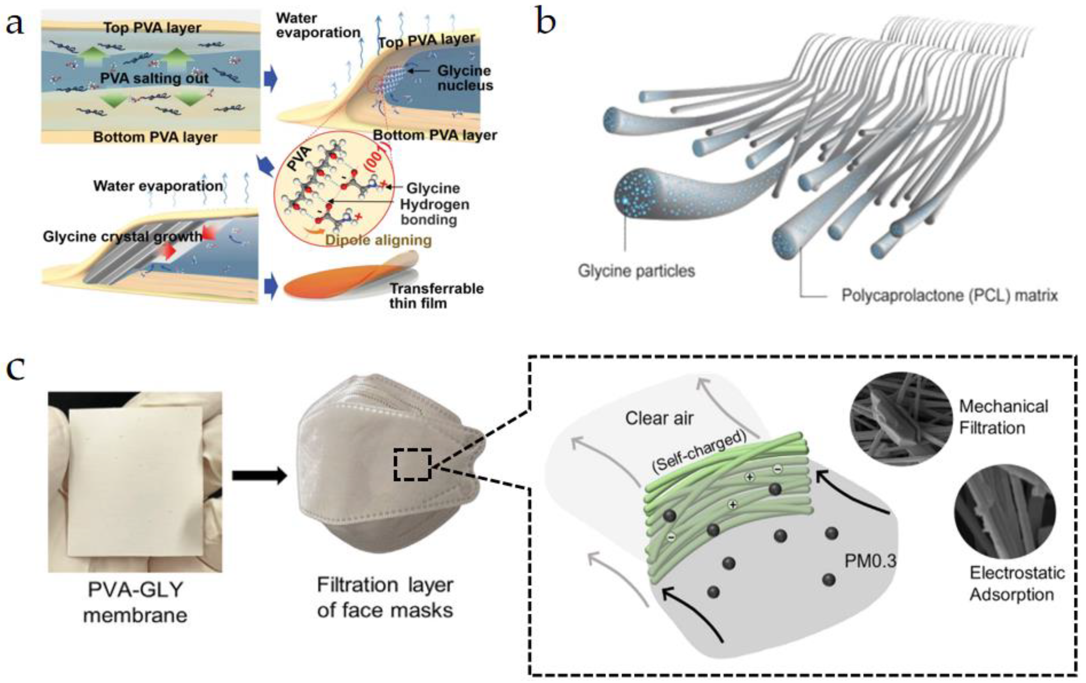
- Yu, Q.; Bai, Y.; Li, Z.; Jiang, F.; Luo, R.; Gai, Y.; Liu, Z.; Zhou, L.; Wang, Y.; Li, C.; et al. Interface-induced high piezoelectric γ-glycine-based flexible biodegradable films. Nano Energy 2024, 121, 109196. [Google Scholar] [CrossRef]
- Zhang, Z.; Li, X.; Peng, Z.; Yan, X.; Liu, S.; Hong, Y.; Shan, Y.; Xu, X.; Jin, L.; Liu, B.; et al. Active self-assembly of piezoelectric biomolecular films via synergistic nanoconfinement and in-situ poling. Nat. Commun. 2023, 14, 4094. [Google Scholar] [CrossRef] [PubMed]
- Zhang, H.; Tang, Y.; Gu, Z.; Wang, P.; Chen, X.; Lv, H.; Li, P.; Jiang, Q.; Gu, N.; Ren, S.; et al. Biodegradable ferroelectric molecular crystal with large piezoelectric response. Science 2024, 383, 1492–1498. [Google Scholar] [CrossRef] [PubMed]
- Zhang, Z.; Liu, S.; Pan, Q.; Hong, Y.; Shan, Y.; Peng, Z.; Xu, X.; Liu, B.; Chai, Y.; Yang, Z. Van der Waals Exfoliation Processed Biopiezoelectric Submucosa Ultrathin Films. Adv. Mater. 2022, 34, 2200864. [Google Scholar] [CrossRef] [PubMed]
- He, Z. Study on preparation, structure and property of 0–3 type PZT/PVDF piezoelectric composite. Master’s Thesis, Wuhan University of Technology, Wuhan, China, May 2003. [Google Scholar]
- Jiang, X. Study on preparation and properties of acrylonitrile butadiene rubber piezoelectric composite. Master’s Thesis, Beijing University of Chemical Technology, Beijing, China, May 2008. [Google Scholar]
- Wang, W.; Liang, L.; Lin, X. Preparation and Performance of 0–3 Type Piezoelectric Ceramic/Rubber Composite. Dev. Appl. Mater. 2014, 29, 67–71. [Google Scholar]
- Sorayani Bafqi, M.; Bagherzadeh, R.; Latifi, M. Fabrication of composite PVDF-ZnO nanofiber mats by electrospinning for energy scavenging application with enhanced efficiency. J. Polym. Res. 2015, 22, 130. [Google Scholar] [CrossRef]
- Szewczyk, P.; Gradys, A.; Kim, S. Persano, L.; Marzec, M.; Kryshtal, A.; Busolo, T.; Toncelli, A.; Pisignano, D.; Bernasik, A.; et al. Enhanced piezoelectricity of electrospun polyvinylidene fluoride fibers for energy harvesting. ACS Appl. Mater. Interfaces 2020, 12, 13575–13583. [Google Scholar] [CrossRef] [PubMed]
- Kumar, M.; Kumari, P. P (VDF-TrFE)/ZnO nanocomposite synthesized by electrospinning: Effect of ZnO nanofiller on physical, mechanical, thermal, rheological and piezoelectric properties. Polym. Bull. 2023, 80, 4859–4878. [Google Scholar] [CrossRef]
- Su, K. Study on Preparation of High Dielectric Composite Materials by Electrospinning. Master’s Thesis, Beijing University of Chemical Technology, Beijing, China, June 2023. [Google Scholar]
- Chen, Q.; Cao, Y.; Lu, Y.; Akram, W.; Ren, S.; Niu, L.; Sun, Z.; Fang, J. Hybrid Piezoelectric/Triboelectric Wearable Nanogenerator Based on Stretchable PVDF–PDMS Composite Films. ACS Appl. Mater. Interfaces 2024, 16, 6239–6249. [Google Scholar] [CrossRef]
- Luo, Y.; Liu, J.; Xiao, Y.; Zhang, J.; Wu, Y.; Zhao, Z. Investigation of the piezoelectric performance of P (VDF-TrFE)/SnO2NPs/GR composite film fabricated via electrospinning. Polym.-Plast. Technol. Mater. 2024, 63, 203–219. [Google Scholar]
- Li, X.; Zhang, Z.; Peng, Z.; Yan, X.; Hong, Y.; Liu, S.; Lin, W.; Shan, Y.; Wang, Y.; Yang, Z. Fast and versatile electrostatic disc microprinting for piezoelectric elements. Nat. Commun. 2023, 14, 6488. [Google Scholar] [CrossRef]
- Avcıoğlu, S.; Uyan, P.; Yontar, O.; Cevik, S. Electrospray deposition of AlN-PVA composite coating as thermal interface material. Mater. Lett. 2022, 318, 132235. [Google Scholar] [CrossRef]
- Park, J.; Han, J.; Gal, C.; Oh, J.; Kim, J.; Kate, K.; Atre, S.; Kim, Y.; Park, S. Fabrication of micro-sized piezoelectric structure using powder injection molding with separated mold system. Ceram. Int. 2018, 44, 12709–12716. [Google Scholar] [CrossRef]
- Hao, Y.; Hou, Y.; Xu, H.; Gao, X.; Zheng, M.; Zhu, M. Enhancing the energy harvesting performance of PDMS based piezocomposites via a synergistic effect. J. Mater. Chem. C 2021, 9, 14303–14308. [Google Scholar] [CrossRef]
- Zhang, J.; Wang, Q.; Liu, A.; Tao, W.; Wei, H.; Li, C. Preparation of 1–3 Piezoelectric Ceramic/Polymer Composite by Ceramic Injection Molding and Their Performance Study. Dev. Appl. Mater. 2017, 32, 86–88. [Google Scholar]
- Han, J.; Gal, C.; Park, J.; Kim, J.; Lee, S.; Yeo, B.; Lee, B.; Park, S.; Park, S. Powder injection molding process for fabrication of piezoelectric 2D array ultrasound transducer. Smart Mater. Struct. 2018, 27, 075058. [Google Scholar] [CrossRef]
- Park, J.; Han, J.; Oh, J.; Park, S.; Kim, Y.; Jang, J.; Lee, W.; Park, S. Design, fabrication of honeycomb-shaped 1–3 connectivity piezoelectric micropillar arrays for 2D ultrasound transducer application. Ceram. Int. 2020, 46, 12023–12030. [Google Scholar] [CrossRef]
- Yan, M.; Zhong, J.; Liu, S.; Xiao, Z.; Yuan, X.; Zhai, D.; Zhou, K.; Li, Z.; Zhang, D.; Bowen, C.; et al. Flexible pillar-base structured piezocomposite with aligned porosity for piezoelectric energy harvesting. Nano Energy 2021, 88, 106278. [Google Scholar] [CrossRef]
- Xie, M.; Zhang, Y.; Kraśny, M.; Bowen, C.; Khanbareh, H.; Gathercole, N. Flexible and active self-powered pressure, shear sensors based on freeze casting ceramic-polymer composites. Energy Environ. Sci. 2018, 11, 2919–2927. [Google Scholar] [CrossRef] [PubMed]
- Fukushima, M.; Fujiwara, T.; Fey, T.; Kakimoto, K. One-or two-dimensional channel structures and properties of piezoelectric composites via freeze-casting. J. Am. Ceram. Soc. 2017, 100, 5400–5408. [Google Scholar] [CrossRef]
- Grinberg, D.; Siddique, S.; Le, M.; Liang, R.; Capsal, J.; Cottinet, P. 4D Printing based piezoelectric composite for medical applications. J. Polym. Sci. Part B Polym. Phys. 2019, 57, 109–115. [Google Scholar] [CrossRef]
- Zeng, Y.; Jiang, L.; Sun, Y.; Yang, Y.; Quan, Y.; Wei, S.; Lu, G.; Li, R.; Rong, J.; Chen, Y.; et al. 3D-printing piezoelectric composite with honeycomb structure for ultrasonic devices. Micromachines 2020, 11, 713. [Google Scholar] [CrossRef] [PubMed]
- Sebastian, T.; Bach, M.; Geiger, A.; Lusiola, T.; Kozielski, L.; Clemens, F. Investigation of electromechanical properties on 3-D printed piezoelectric composite scaffold structures. Materials 2021, 14, 5927. [Google Scholar] [CrossRef] [PubMed]
- Li, J.; Yang, F.; Long, Y.; Dong, Y.; Wang, Y.; Wang, X. Bulk ferroelectric metamaterial with enhanced piezoelectric and biomimetic mechanical properties from additive manufacturing. ACS Nano 2021, 15, 14903–14914. [Google Scholar] [CrossRef]
- Wang, L.; Zhang, J.; Li, G.; Ge, X.; Teng, M.; Li, Y. Dielectric relaxation behavior of PVDF-based composites filled with different nanofillers. Acta Mater. Compos. Sin. 2014, 31, 880–887. [Google Scholar]
- Hong, S.; Lee, J.; Kim, K.; Choi, S. Electrospun Poly L-Lactic Acid Nanofiber Webs Presenting Enhanced Piezoelectric Properties. Polymers 2024, 16, 347. [Google Scholar] [CrossRef]
- Yang, X.; Li, H.; Fang, B.; Zhang, S.; Lu, X.; Ding, J. Enhancing piezoelectricity of low-temperature-sintered PZT-BNZ ceramics by pulse poling. J. Mater. Sci. Mater. Electron. 2024, 35, 611. [Google Scholar] [CrossRef]
- Tian, G.; Deng, W.; Da, X.; Yang, T.; Zhang, B.; Ren, X.; Lan, B.; Zhong, S.; Jin, L.; Zhang, H.; et al. Dielectric micro-capacitance for enhancing piezoelectricity via aligning MXene sheets in composites. Cell Rep. Phys. Sci. 2022, 3, 100814. [Google Scholar] [CrossRef]
- Thirumalasetty, A.; Pamula, S.; Krishnan, T.; Khade, V.; Sharief, P.; Venkata, S.; Adiraj, S.; Wuppulluri, M. Energy storage and catalytic behaviour of cmWave assisted BZT and flexible electrospun BZT fibers for energy harvesting applications. Sci. Rep. 2024, 14, 2650. [Google Scholar] [CrossRef]
- Verma, K.; Sharma, R. A flexible piezoelectric generator based on KNN/PVDF composite films: Role of KNN concentration on the piezoelectric performance of generator. Chin. J. Phys. 2023, 84, 198–215. [Google Scholar] [CrossRef]
- Fathollahzadeh, V.; Khodaei, M. Enhanced piezoelectric response of PVDF by incorporating of BaTiO3 nanoparticles and surface treatment. J. Mater. Sci. Mater. Electron. 2024, 35, 107. [Google Scholar] [CrossRef]
- Silakaew, K.; Saijingwong, W.; Meeporn, K.; Maensiri, S.; Thongbai, P. Effects of processing methods on dielectric properties of BaTiO3/poly (vinylidene fluoride) nanocomposites. Microelectron. Eng. 2015, 146, 1–5. [Google Scholar] [CrossRef]
- Mo, X. Progress and Opportunities of Underwater Transducers in China. Bull. Chin. Acad. Sci. 2019, 34, 272–282. [Google Scholar]
- Wen, X.; Sun, Y.; Shen, Y. Research on underwater acoustic communication system of micro-unmanned underwater vehicle. Foreign Electron. Meas. Technol. 2022, 41, 76–82. [Google Scholar]
- Su, J.; Wang, H. Research on high sensitivity integrated transmit and receive hydroacoustic transducer. Phys. Scr. 2023, 98, 125028. [Google Scholar] [CrossRef]
- Wang, J.; Zhong, C.; Hao, S.; Lv, N.; Wang, L. Design of planar array transducers based on connected 1–3 piezoelectric composites. Micromachines 2021, 12, 1417. [Google Scholar] [CrossRef]
- Wang, L.; Dong, T.; Qin, L.; Wang, G. Fabrication and Performance of Piezoelectric Composite with Multi-elements. Piezoelectrics Acoustooptics 2010, 32, 433–436. [Google Scholar]
- Lu, Z.; Gao, G. Research Progress in PVDF Piezoelectric Composites and Their Applications. Micronanoelectric Technol. 2023, 60, 1356–1365. [Google Scholar]
- Lin, X. Investigations on the Design, Characterization and Applications of Flexible Pressure Sensor Based on Piezoelectric Composite. Ph.D. Thesis, Guangdong University of Technology, Guangzhou, China, May 2021. [Google Scholar]
- Wen, D.; Sun, D.; Huang, P.; Huang, W.; Su, M.; Wang, Y.; Han, M.; Kim, B.; Brugger, J.; Zhang, H.; et al. Recent progress in silk fibroin-based flexible electronics. Microsyst. Nanoeng. 2021, 7, 35. [Google Scholar] [CrossRef] [PubMed]
- Tian, G.; Deng, W.; Yang, T.; Zhang, J.; Xu, T.; Xiong, D.; Lan, B.; Wang, S.; Sun, Y.; Ao, Y.; et al. Hierarchical Piezoelectric Composites for Noninvasive Continuous Cardiovascular Monitoring. Adv. Mater. 2024, 36, 2313612. [Google Scholar] [CrossRef] [PubMed]
- Huang, Y.; Chen, S.; Li, Y.; Lin, Q.; Wu, Y.; Shi, Q. Flexible piezoelectric sensor based on PAN/MXene/PDA@ ZnO composite film for human health and motion detection with fast response and highly sensitive. Chem. Eng. J. 2024, 488, 150997. [Google Scholar] [CrossRef]
- Wang, X.; Yang, B.; Liu, J.; Zhu, Y.; Yang, C.; He, Q. A flexible triboelectric-piezoelectric hybrid nanogenerator based on P (VDF-TrFE) nanofibers and PDMS/MWCNT for wearable devices. Sci. Rep. 2016, 6, 36409. [Google Scholar] [CrossRef]
- Chen, T.; Wei, Q.; Ma, Y.; Tang, Y.; Ma, L.; Deng, S.; Xu, B. Multifunctional Electronic Skins for Ultra-Sensitive Strain, Temperature, Humidity Sensing, and Energy Harvesting. Nano Energy 2024, 127, 109752. [Google Scholar] [CrossRef]
- Ren, Y.; Gao, G. Research and Development of Sensors in the Field of Pulse Diagnosis. China Ceram. 2023, 59, 1–15. [Google Scholar]
- Khanbareh, H.; De Boom, K.; Schelen, B.; Scharff, R.; Wang, C.; Zwaag, S.; Groen, P. Large area and flexible micro-porous piezoelectric materials for soft robotic skin. Sens. Actuators A Phys. 2017, 263, 554–562. [Google Scholar] [CrossRef]
- Liu, Y.; Zheng, H.; Zhao, L.; Liu, S.; Yao, K.; Li, D.; Yiu, C.; Gao, S.; Avila, R.; Chirarattananon, P.; et al. Electronic skin from high-throughput fabrication of intrinsically stretchable lead zirconate titanate elastomer. Research 2020, 2020, 1085417. [Google Scholar] [CrossRef]
- Wu, Z.; Dai, Y.; Zeng, Y. Intelligent robot-assisted fracture reduction system for the treatment of unstable pelvic fractures. J. Orthop. Surg. Res. 2024, 19, 271. [Google Scholar] [CrossRef] [PubMed]
- Li, J.; Ke, Y.; Xie, J. Design of Intelligent Inspection Robot System Based on Multi- source Perception. Microcomput. Appl. 2024, 40, 15–18+22. [Google Scholar]
- Zhou, Y.; Zhao, X.; Xu, J.; Chen, G.; Tat, T.; Li, J.; Chen, J. A multimodal magnetoelastic artificial skin for underwater haptic sensing. Sci. Adv. 2024, 10, eadj8567. [Google Scholar] [CrossRef] [PubMed]
- Lin, L.; Guo, J.; Liu, L. Multi-scene application of intelligent inspection robot based on computer vision in power plant. Sci. Rep. 2024, 14, 10657. [Google Scholar] [CrossRef] [PubMed]
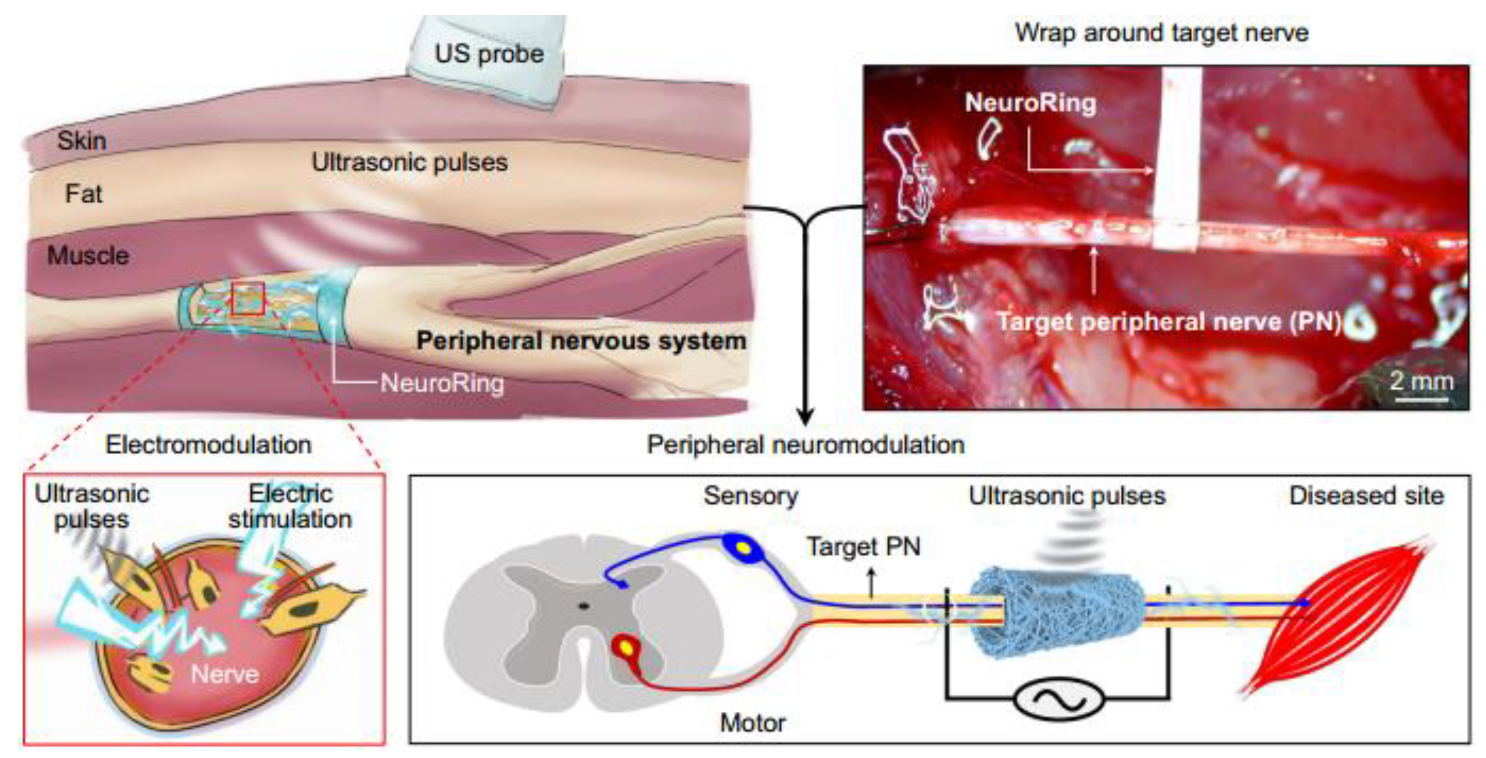
- Li, T.; Wei, Z.; Jin, F.; Yuan, Y.; Zheng, W.; Qian, L.; Wang, H.; Hua, L.; Ma, J.; Zhang, H.; et al. Soft ferroelectret ultrasound receiver for targeted peripheral neuromodulation. Nat. Commun. 2023, 14, 8386. [Google Scholar] [CrossRef] [PubMed]
- Wang, A.; Ma, X.; Yang, Y.; Shi, G.; Han, L.; Hu, X.; Shi, R.; Yan, J.; Guo, Q.; Zhao, Y. Biophysical-driven piezoelectric and aligned nanofibrous scaffold promotes bone regeneration by re-establishing physiological electrical microenvironment. Nano Res. 2024, 1–18. [Google Scholar] [CrossRef]
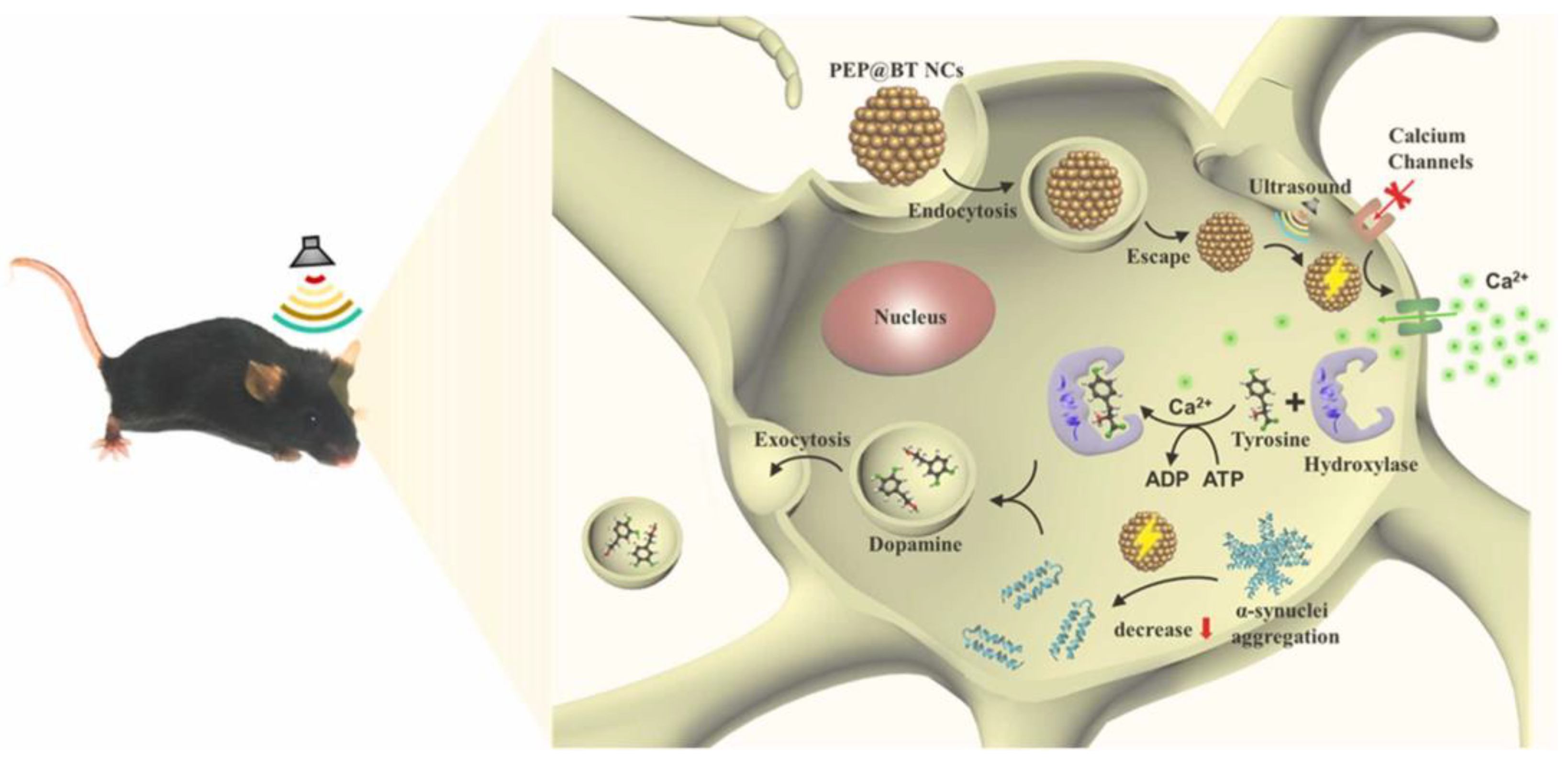
- Chen, Y.; Feng, P.; Zhong, G.; Liu, J.; Jiang, B.; Harn, Y.; Zhao, D.; Lin, Z.; Zhang, Q.; Shen, Q. Piezoelectric nanogenerators enabled neuromodulation rescued dopaminergic neuron loss in Parkinson’s disease. Nano Energy 2024, 121, 109187. [Google Scholar] [CrossRef]
- Tian, G.; Deng, W.; Gao, Y.; Xiong, D.; Yan, C.; He, X.; Yang, T.; Jin, L.; Chu, X.; Zhang, H.; et al. Rich lamellar crystal baklava-structured PZT/PVDF piezoelectric sensor toward individual table tennis training. Nano Energy 2019, 59, 574–581. [Google Scholar] [CrossRef]
- Yamashita, T.; Kobayashi, T. Smart table tennis racket using a rubber mounted ultrathin piezoelectric sensor array. Sens. Mater. 2021, 33, 1081–1089. [Google Scholar] [CrossRef]
- Guan, Y.; Bai, M.; Li, Q.; Li, W.; Liu, G.; Liu, C.; Chen, Y.; Lin, Y.; Hui, Y.; Wei, R. A plantar wearable pressure sensor based on hybrid lead zirconate-titanate/microfibrillated cellulose piezoelectric composite films for human health monitoring. Lab Chip 2022, 22, 2376–2391. [Google Scholar] [CrossRef]
- Gao, X.; Zheng, M.; Lv, H.; Zhang, Y.; Zhu, M.; Hou, Y. Ultrahigh sensitive flexible sensor based on textured piezoelectric composites for preventing sports injuries. Compos. Sci. Technol. 2022, 229, 109693. [Google Scholar] [CrossRef]
- Zeng, W.; Deng, W.; Yang, T.; Wang, S.; Sun, Y.; Zhang, J.; Ren, X.; Jin, L.; Tang, L.; Yang, W. Gradient CNT/PVDF piezoelectric composite with enhanced force-electric coupling for soccer training. Nano Res. 2023, 16, 11312–11319. [Google Scholar] [CrossRef]
- Zhang, J.; Zhang, Y.; Yang, J.; Wang, X. Beyond Color Boundaries: Pioneering Developments in Cholesteric Liquid Crystal Photonic Actuators. Micromachines 2024, 15, 808. [Google Scholar] [CrossRef]
- Wang, C.; Li, X.; Hu, H.; Zhang, L.; Huang, Z.; Lin, M.; Zhang, Z.; Yin, Z.; Huang, B.; Gong, H.; et al. Monitoring of the central blood pressure waveform via a conformal ultrasonic device. Nat. Biomed. Eng. 2018, 2, 687–695. [Google Scholar] [CrossRef] [PubMed]
- Jiang, L.; Lu, G.; Zeng, Y.; Sun, Y.; Kang, H.; Burford, J.; Gong, C.; Humayun, M.; Chen, Y.; Zhou, Q. Flexible ultrasound-induced retinal stimulating piezo-arrays for biomimetic visual prostheses. Nat. Commun. 2022, 13, 3853. [Google Scholar] [CrossRef]
- Wang, Q.; Zhang, Y.; Xue, H.; Zeng, Y.; Lu, G.; Fan, H.; Jiang, L.; Wu, J. Lead-free dual-frequency ultrasound implants for wireless, biphasic deep brain stimulation. Nat. Commun. 2024, 15, 4017. [Google Scholar] [CrossRef]


| Types of Sensors | Main Applications | Advantages | Disadvantages |
|---|---|---|---|
| piezoelectric [13,14,16] | weapon guidance, industrial inspection, ocean exploration, medical diagnosis | strong self-powering, capability, rapid response speed, flexible structure, excellent transmitting/receiving performance | limited frequency response, weak direct current response, high cost |
| piezoresistive [18] | pressure sensing, motion monitoring | easy integration, simple structure, low power consumption | weak temperature stability, complex fabrication process, susceptible to external interference |
| Magnetostrictive [19,20] | liquid level measurement acoustic measurement, structural monitoring | high precision, large measuring range, fast response speed | weak anti-interference capability, short product lifespan, complex signal processing |
| Capacitive [20] | pressure sensing, industrial inspection, motion monitoring | high resolution, fast response speed, great dynamic response | complex power supply system, high maintenance requirements, high cost |
| Inductive [20,21] | displacement measurement, humidity measurement, non-destructive testing | high sensitivity, strong durability, great dynamic response | weak anti-interference capability, high-temperature error, large volume |
| Preparation Process Type | Literature Source | Piezoelectric Strain Coefficient | Bending Radius | Electro- Mechanical Coupling Coefficient | Fracture Stress | Fracture Strain | Maximum Output Voltage | Maximum Output Current | Advantages | Disadvantages | Potential Applications |
|---|---|---|---|---|---|---|---|---|---|---|---|
| Molding by Hot Pressing | He [101] | ~45pC/N | / | ~0.12 | / | / | / | / | Simple process, suitable for mass production | High thermal stability requirements, weak piezoelectric performance. | Actuators, energy harvesters. |
| Electro- spinning | Ali [70] | / | / | / | 30~40 MPa | ~5.0% | 4.42 V | / | High precision, can produce flexible materials with high piezoelectric properties | Low yield, high equipment operation requirements. | Wearable devices, implantable devices. |
| Su [107] | / | / | / | 35 MPa | 2.25~4.3% | 200 V | 0.5 μA | ||||
| Chen [108] | / | / | / | / | / | 88 V | 5.85 μA | ||||
| Electrospray Deposition | Li [110] | 560 pm/V | / | / | / | / | 30 V | / | Ultra-fast preparation efficiency and precision; excellent piezoelectric film performance | Not suitable for developing large-sized materials, relatively complex process. | Wearable devices, energy harvesters. |
| Dice-Fill | Hou [85] | / | 30 mm | 0.74 | / | / | / | / | Simple process, suitable for developing large-sized composite materials | Low processing precision, not suitable for developing small-sized materials. | Underwater acoustic transducers, and ultrasonic transducers. |
| Hao [86] | 464.3 pC/N | 150 mm | 0.70 | / | / | / | / | ||||
| Injection- Molding | Zhang [114] | 530 pC/N | / | 0.65 | / | / | / | / | Simple process, developing composites with high aspect ratios or complex structures. | High cost and high mold design requirements. | Ultrasonic transducers, medical diagnostic devices. |
| Freeze- Casting | Yan [117] | 354~434 pC/N | / | / | / | / | 30.2 V | 13.8 μA | Suitable for developing porous ceramic-based composites. | Long process cycle, high mold requirements. | Energy harvesters, tactile sensors. |
| Xie [118] | 750 pC/N | 8 mm | / | / | / | 1.2 V | / | ||||
| 3D Printing | Zeng [121] | 60 pC/N | / | ~0.31 | / | / | 0.18 V | / | Developing composites with complex structures, highly adaptable. | High requirements for materials and equipment. | Micro ultrasonic transducers, bionic sensors. |
| Li [123] | 153 pC/N | / | / | 5.5 MPa | / | 6 V | 30.18 μA |
Disclaimer/Publisher’s Note: The statements, opinions and data contained in all publications are solely those of the individual author(s) and contributor(s) and not of MDPI and/or the editor(s). MDPI and/or the editor(s) disclaim responsibility for any injury to people or property resulting from any ideas, methods, instructions or products referred to in the content. |
© 2024 by the authors. Licensee MDPI, Basel, Switzerland. This article is an open access article distributed under the terms and conditions of the Creative Commons Attribution (CC BY) license (https://creativecommons.org/licenses/by/4.0/).
Share and Cite
Zhang, J.; Wang, J.; Zhong, C.; Zhang, Y.; Qiu, Y.; Qin, L. Flexible Electronics: Advancements and Applications of Flexible Piezoelectric Composites in Modern Sensing Technologies. Micromachines 2024, 15, 982. https://doi.org/10.3390/mi15080982
Zhang J, Wang J, Zhong C, Zhang Y, Qiu Y, Qin L. Flexible Electronics: Advancements and Applications of Flexible Piezoelectric Composites in Modern Sensing Technologies. Micromachines. 2024; 15(8):982. https://doi.org/10.3390/mi15080982
Chicago/Turabian StyleZhang, Jinying, Jiacheng Wang, Chao Zhong, Yexiaotong Zhang, Yajuan Qiu, and Lei Qin. 2024. "Flexible Electronics: Advancements and Applications of Flexible Piezoelectric Composites in Modern Sensing Technologies" Micromachines 15, no. 8: 982. https://doi.org/10.3390/mi15080982