1. Introduction
Nowadays, positioning mechanical components becomes very important for micro/nano applications such as cell manipulation, surgery, aerospace, micro fluidics, optical systems, micro machining and micro assembly etc. [
1]. As an essential part of micro/nano manufacturing technology, high-precision positioning devices with controlled motions at sub-micron level is needed. The desired motion is provided with the deflection of these flexible joints called in the literature as “flexures” and the mechanisms, which are composed of flexures, instead of rigid joints are called “compliant mechanisms” [
2]. The compliant parallel mechanisms/modules (CPMs) transmit motions/force by deflections of their compliant members and have characteristics of conventional CPMs. On the one hand, the CPMs have many advantages to be applied in high-precision applications providing high resolution, frictionless, smooth and continuous motion. On the other hand, the CPMs allow small displacements up to 0.01 μm with submicron accuracy, whose motion is insensitive to temperature changes due to their symmetrical structure, and provide weight reduction, compact structure and cheaper manufacturing cost than the high-precision mechanisms that use conventional rigid joints.
Parallel kinematic structures are mostly employed in micro positioning stages because of their advantages such as zero backlash, no need for lubrication, reduced wear, high precision, compact structure and monolithic configuration, but puzzled by their limited workspace, dexterity, non-linear kinematics, and difficult calculation of forward kinematics [
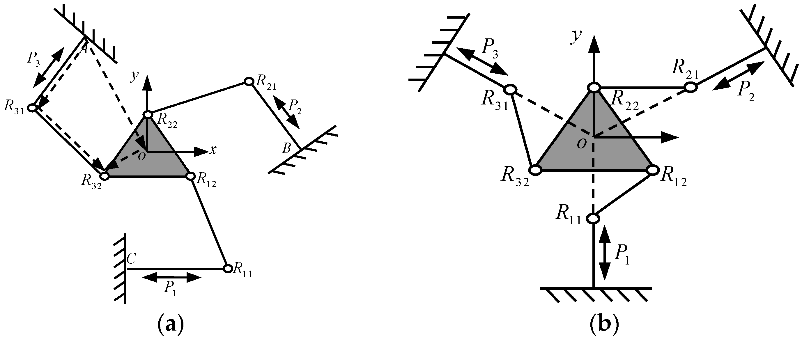
3]. Fortunately, these drawbacks can be avoided for flexure-based compliant mechanisms because of their micro range motion. In addition, the kinematics can be assumed linear in the workspace range due to the small flexure displacements. The repeatability of these structures is eliminated with fewer flexures as there are no backlash or friction problems in the joints compared with rigid mechanisms. Various types of CPMs have been used in compliant positioning stages in the literature. These mechanisms are based on rigid body parallel prototypes. Many planar parallel compliant mechanisms have been designed based on triangular stages, in which, for compliant mechanisms, the most common kinematic structure 3-RRR is used [
4]. Three linkages connected to each other with three revolute joints actuate the triangular stage. The end-effector has translation motion along
x-
y direction and a rotation about the
z direction. This type of parallel kinematic structure amplifies the motion of the actuators. The revolute joints were replaced with flexure hinges, which were designed according to the desired parallel kinematic performance. Another triangular stage has 3-PRR kinematic structure, which is composed of 1 prismatic and 2 revolute joints and is used in [
5] as a CPM.
There are three main approaches to designing CPMs: (a) Pseudo-Rigid-Body-Model synthesis methods proposed by Howell and Midha [
6,
7]; (b) Continuum Structure Optimization methods [
8,
9]; and (c) innovative design methods such as the constraint-based design approach, the building block approach [
10,
11], the screw theory-based approach and the freedom and constraint topology approach [
12]. In addition, two main methods of solving force-displacement equations are concluded: (a) differential equation-based methods; and (b) energy methods, such as Castigliano’s theorem and virtual work principle. For the compliant mechanisms, there is no apparent boundary to identify the degrees-of-freedom (DOF) or the degrees-of-constraint (DOC) due to complex issues such as dimension, loads and motion range. The DOF of compliant mechanisms, especially in planar compliant mechanisms, were determined using the Pseudo-Rigid-Body-Model concept. [
13] proposed an eigenscrew-based method to determine the DOF or compliance of compliant mechanisms. In addition, the constraint-based design approach, the screw theory-based approach and the freedom and constraint topology approach (FACT) [
14,
15] have been proposed to analyze the DOF and/or DOC of compliant mechanisms. Although the CPMs have great advantages to be used as micro positioning stages for high-precision applications, they are very sensitive to manufacturing tolerances and assembly errors. In analyzing the DOF of a compliant mechanism quantitatively, it is difficult to realize the spatial multi-DOF micro/nano positioning operation with the compliant mechanism. Concerned with this issue, some researchers designed a new type of fully compliant parallel mechanism, which replaces the flexible hinge with a rigid hinge, to integrate conventional parallel spatial multi-DOF mechanism characteristics into compliant mechanism [
16,
17]. However, the design often depends on the designer’s experience, which will lead to the diversity of flexible hinge configuration, namely, only the hinges are flexible but the other parts are still rigid. The kinematics and dynamics analysis of rigidity-flexibility hybrid pattern have become more complicated and the overall rigidity of compliant mechanism is lacking. Therefore, it is hard to effectively suppress the disturbance of environmental random vibration and guarantee precision positioning and machining accuracy. Moreover, it is also difficult to satisfy the requirements of overall rigidity and precision requirement [
4].
Hao and Kong [
5,
18,
19] performed a nonlinear analysis of spatial CPM-based multi-beam modules and proposed a normalization-based approach for the mobility analysis of this class of spatial compliant parallel modules (CPMs) to address the dimensional-inhomogeneity issue of motion/load. The normalization strategy (non-dimensional/homogeneous measures) can unify the dimensions of compliant mechanisms and be used in modeling and the design of compliant/flexural mechanisms. Zhang et al. [
20] researched the coupling characteristics of elastic motions and rigid body motions for a 3-PRR planar parallel manipulator with three flexible intermediate links to eliminate unwanted flexible vibrations, and the designed lightweight manipulator had the capability of moving swiftly but was deprived of practicability.
Among the analytical methods used for structure innovation design, the evolutionary structural optimization (ESO) method is a good choice for its simplicity and ease of implementation with a general finite element software. Xie and Steven roposed the concept of gradually removing redundant material in the method of finite element analysis to achieve an optimal design [
21]. It also has been demonstrated for more practical problems with multiple load cases or to optimize for structural frequency. A procedure to deal with the problems of stiffness constraint and a modified rejection ratio for multiple load case ESO has been developed for better results. It was also found that the element size had a significant effect on the history of minimum stresses and volume reduction as well. The optimized structure topology is mainly controlled by element size. The choice of the initial rejection ratio and the evolutionary rate also have significant influence on structure topology. Some improved ESO methods based on SIMP are proposed to reduce the step length of evolution for improving the accuracy of sensitivity analysis. The SIMP method is employed to describe the relationship between the relative density and stiffness of elements, the relative densities of elements are taken as the design variables, and the mean compliance is selected as the objective function to prevent checkerboards and eliminate mesh independency [
22,
23]. The proposed strategy firstly obtained a rough design of the structural topology by eliminating less-stressed material, then computed the stiffness and frequency, and analyzed local stress at the last step.
It is revealed that using the criteria of optimization algorithm and vector isomorphic mapping methods will cause diversity result changes under a variety of topology and constraint conditions. In the optimization iterations, elements whose relative densities were less than or equal to rejection ratio were removed from the design domain and all remaining elements were entered into the next iteration. Based on the work in [
24], Wang and Zhu proposed a 3-RRR type CPM for displacement and the work in [
25] also presented a new sensitivity reanalysis of static displacement for arbitrary changes of design variables, which is a key step for this research. This type of CPM has good characteristics such as kinematostatic decoupling and enlarging the range of motion. The homologous 3-PRR mechanism in this type of continuum structure optimized under topology constraints will obtain more benefit for practice.
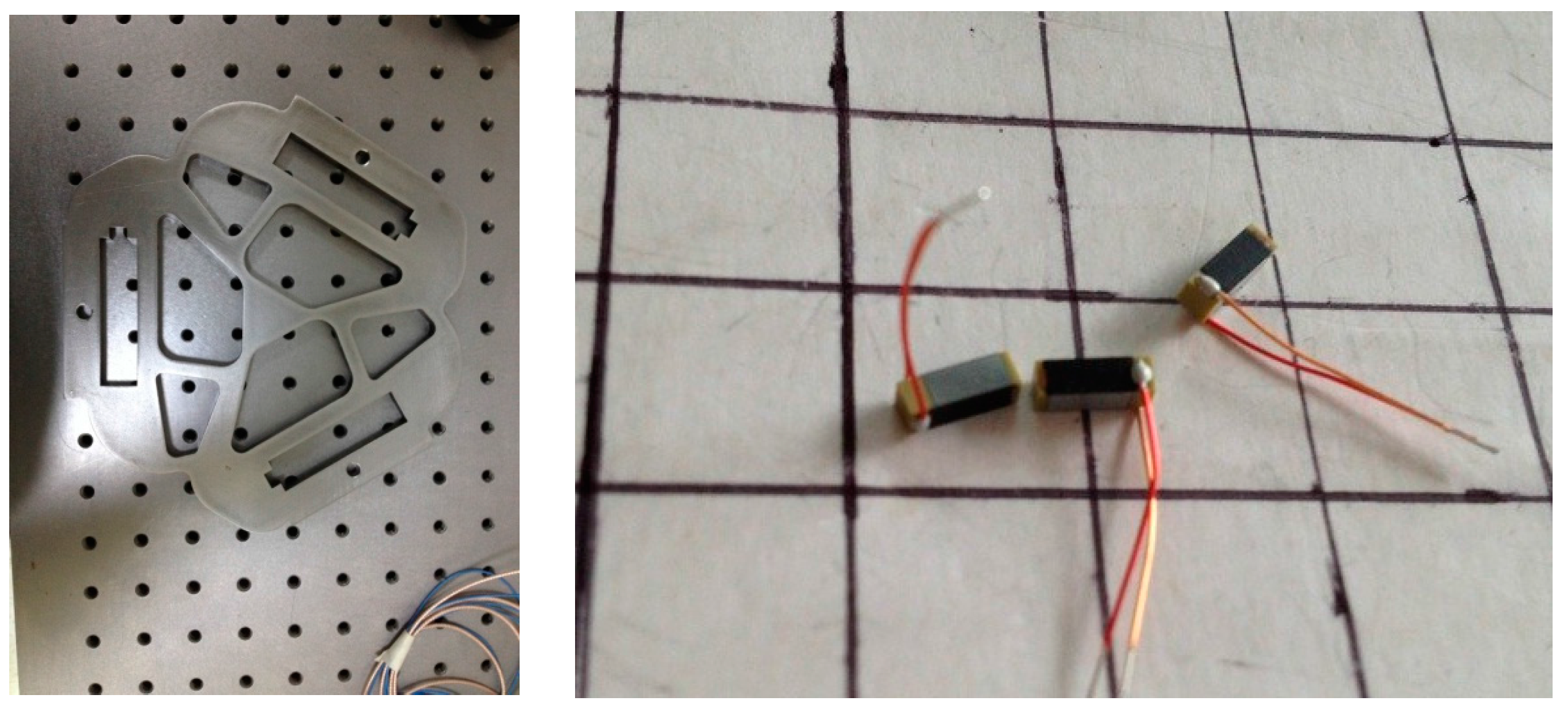
Based on the above methods, this paper further investigates some sorts of continuum structures under special load cases, which cannot be optimized smoothly, or where the later optimization of this continuum structure is terminated abruptly when the removal of material increases excessively. In the optimization iterations, elements whose relative densities were less than or equal to the rejection ratio were removed from the design domain and all remaining elements were retained into the next iteration. It can timely and flexibly adjust the criterion of inefficient material removal. This procedure is based on systematic and gradual removal of the elements with lower stress compared with the maximum stress of the structure. Nevertheless, the method neither directly reflects the kinematics and dynamics performance nor effectively meets high-precision positioning requirements. Fortunately, it can be processed with all the flexible hinges being integrated into a continuum structure using WEDM (Wire-cut Electrical Discharge Machining). The integrated CPMs thus are obtained [
26]. There remains a problem of how to configure flexible hinges in the integrated CPMs. It is necessary to put forward a new design method for CPMs in a continuum structure to obtain high stiffness, mechanism uniqueness and multi-DOF kinematics performance. A practical approach for the new CPMs synthesis uses topology optimization theory with modal parameters, including boundary constraints and load case conditions and maximizing integral stiffness. Several studies have been conducted on the flexibility minimizing with a single objective orient optimization [
27,
28,
29], which adopted a compliant mechanism synthesis method. However, the coupling between the flexibility and vibration-inherent frequency is ignored, and the designed mechanism structure cannot actively suppress the influence of mechanical operation on accuracy due to the random vibration under load case conditions. According to the kinematic characteristics of high-precision micro/nano positioning displacement worktable, a novel planar mechanical form synthesis method for a fully CPM is proposed in this paper. Based on the output criteria of the spatial vector constraint in the parallel mechanism prototype, a multi-objective optimization function was put forward to maximize the limb stiffness and the vibration-inherent frequency. As a peristaltic movement illustration, a 3-PRR planar fully compliant precision positioning micro displacement worktable is considered. The Jacobian matrix of the vector motion is established as multi-objective topology optimization under output-equivalent criteria, and a fully CPM topology optimization model was constructed using the continuum SIMP method [
24,
30] and the ordered multi-material SIMP interpolation could solve multi-material topology optimization problems [
31]. An analysis of the characteristic of CPMs’ kinematics indicates that the main issue is rationally allocating the weights of the compromise programming method and adopting a mean inherent frequency method. The static stiffness, stress distribution, the first 6 modes of vibration-inherent frequency and its modal parameters can be obtained. The experimental results demonstrate that the proposed method is able to obtain a perfect topology mechanism and satisfy positioning displacement accuracy requirement.
This paper is organized as below. The fundamental theory regarding the Jacobian equation construction by vector isomorphism mapping is described in
Section 2. The multi-objective topology optimization model of 3-PRR planar fully CPM is depicted in
Section 3. The processing of multi-objective optimization and analysis with Hyperworks
® (Altair Engineering, Inc., Troy, MI, USA) and Optistruct
® (Altair Engineering, Inc.) respectively is illustrated and discussed in
Section 4. Some experiment results are listed in
Section 5. The conclusion is given in
Section 6.
4. Multi-Objective Topology Optimization and Solution
4.1. Topology Optimization in Load Cases of a Multi-Objective Prototype Mechanism
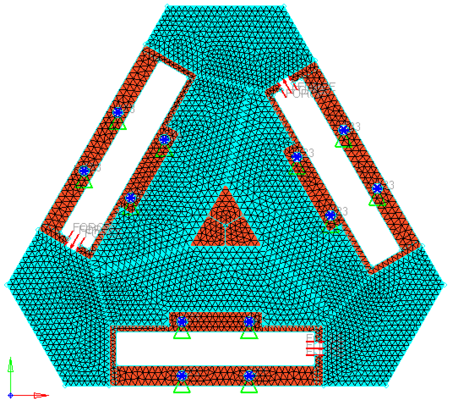
Based on the 3-PRR planar fully CPMs, we sketch a holonomic triangular plate material to satisfy the isomorphic property with flexible hinge by slicing some regular region. Supposing that the elastic modulus of steel plate E is 21,000 Mpa, and Poisson’s ratio μ is 0.3, and material density ρ is 7900 kg/m3, and plate thickness is 8 mm, and volume fraction f0 is 0.4. Adopting 5510 triangle elements and 3029 nodes to fill the design region, the holonomic design system can be obtained.
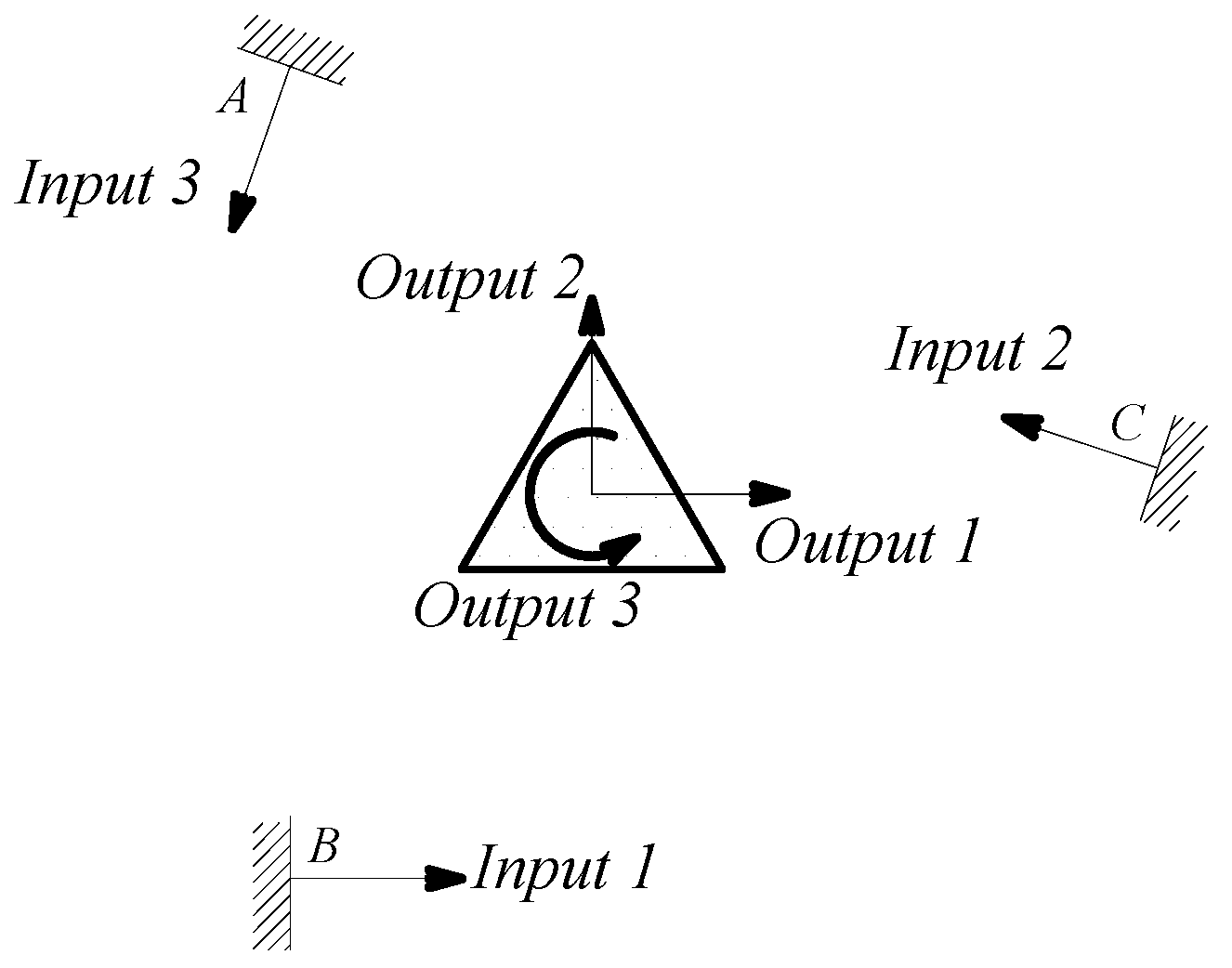
The linkage between moving platform and limbs has intrinsically been changed, shown in
Figure 3. The post-optimality mechanism topology in load case is in free-hinged mode, satisfied with the 3-PRR fully CPMs. The finite element model was solved for each load case, and the von Mises stress distribution was obtained for each load case as the index for material removal (Xie and Steven [
21]). The micro/nano-scale direct driver can be placed in the irregular design region whose scope is constrained to the driver’s build-in size. The prototypical model is built in 3-D software Solidworks
® (Dassault Systèmes SolidWorks Corp, Concord, MA, USA), and preprocessed in CAE software Hyperworks
® include fine removing, material element attributes assignment and input load case. The result is shown in
Figure 4.
A detailed step-by-step algorithm of the multi-objective topology optimization method implemented for the CPM-type planar continuum structure is given as follows.
Step 1: Discretize the origin design domain with a densely finite element mesh as
Figure 4.
Step 2: Define all boundary constraints and apply load conditions according to SIMP model as Equation (18).
Step 3: Assign an initial value to the design variables.
Step 4: Construct the relationship between flexibility C and frequency Λ as Equations (20), (22) and (23).
Step 5: Carry out a linear finite element analysis of the continuum structure.
Step 6: Differentiate the multi-objective formulation for all flexibility analysis as Equations (24), (27) and (28).
Step 7: Calculate the sensitivity of constraint function for all remaining elements as Equation (25).
Step 8: Calculate the optimization criteria as Equation (29) and update the design variables as Equation (30). Elements will be removed if they satisfy Equation (30).
Step 9: If the total volume V of all the remaining elements satisfies the volume constraint as Equation (29) and flexibility C satisfy Equation (31), the optimization process will terminate. Otherwise, the process will return to Step 4.
4.2. The Isomorphic Prototype of 3-PRR Planar Fully CPM
For the removed continuum structure in Hyperworks®, the attributes of selected material are set as material type, stainless steel 304#, Young’s modulus 2.05 × 10⁻⁵ F/mm2, Poisson’s ratio 0.3, material density 7.85 × 10⁻⁹ t/mm3, and the load 1 KN.
According to the continuous mapping topology optimization SIMP model defined as Equation (18), the material assignment in planar fully CPM prototype can be obtained by removing as shown in
Figure 5. The reserved red region in the selected material field is filled with material with the density of 1, except for the non-design redundant material field. The blue region is filled with material with the density of zero, and should be removed from the redundant material field. The flexibility of objective function is shown in
Figure 6, which converges fast after only 5 iterative steps.
4.3. The Analysis and Simulation Result on Topology Optimization
The CAD model from topology optimization of 3-PRR planar fully CPM is imported into Solidworks
®, and also can be used in Hyperworks
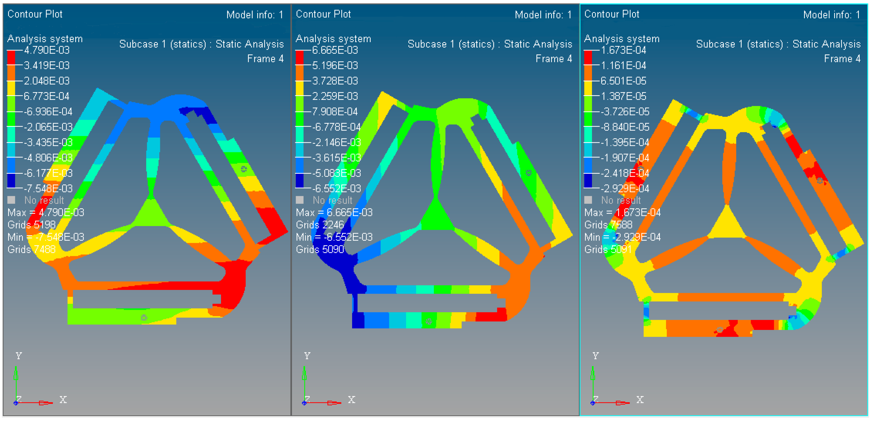
® for kinematostatic simulation associated with processed results. The result of stress distribution is shown in
Figure 7, and the maximum stress is centered in the outputs of drivers with the value of 29.64 MPa, less than the material yield strength.
Comparing the initial design mechanism parameters with optimized mechanism as shown in
Table 1, stress distribution under different boundary constraints in the same load case can be obtained.
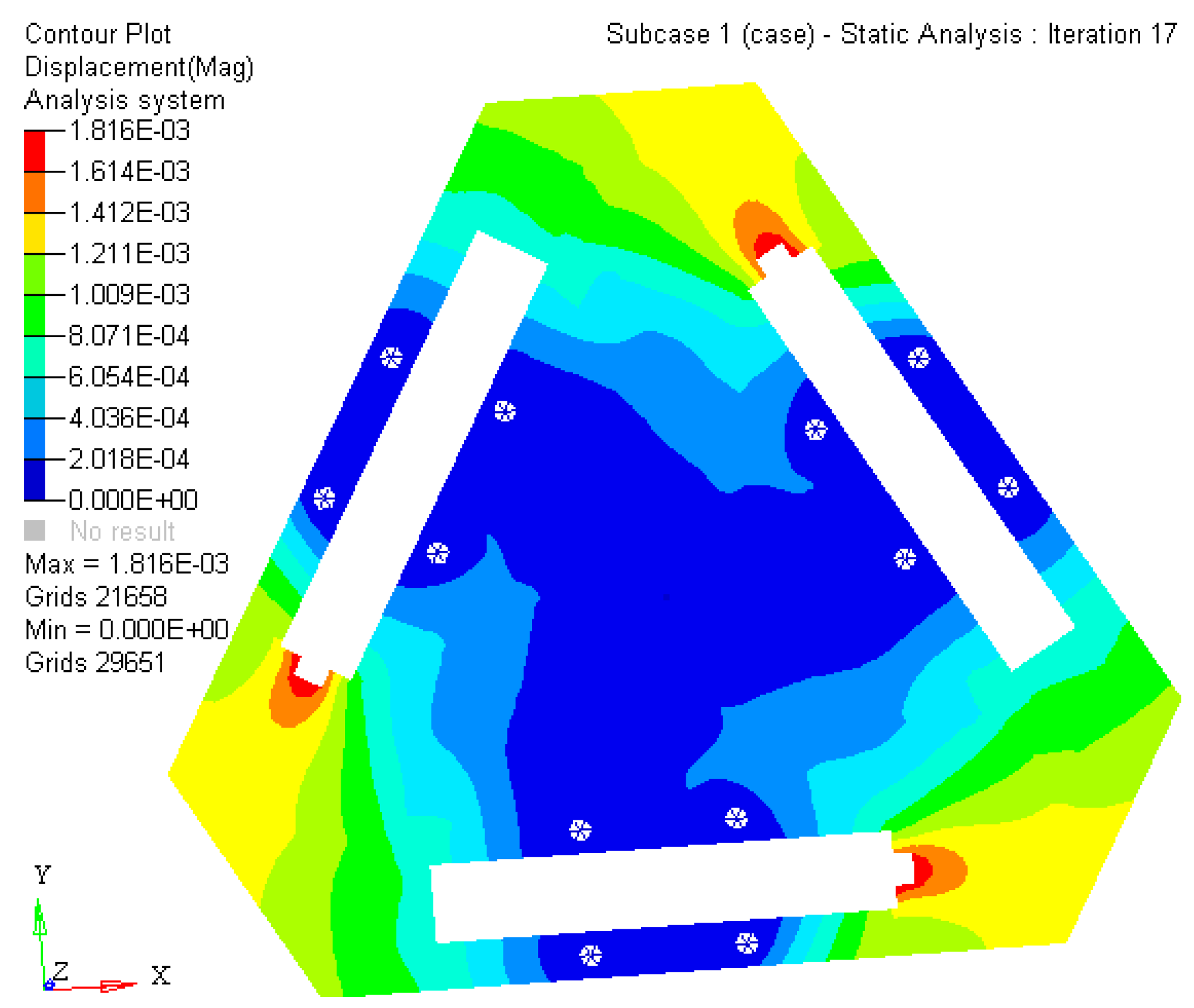
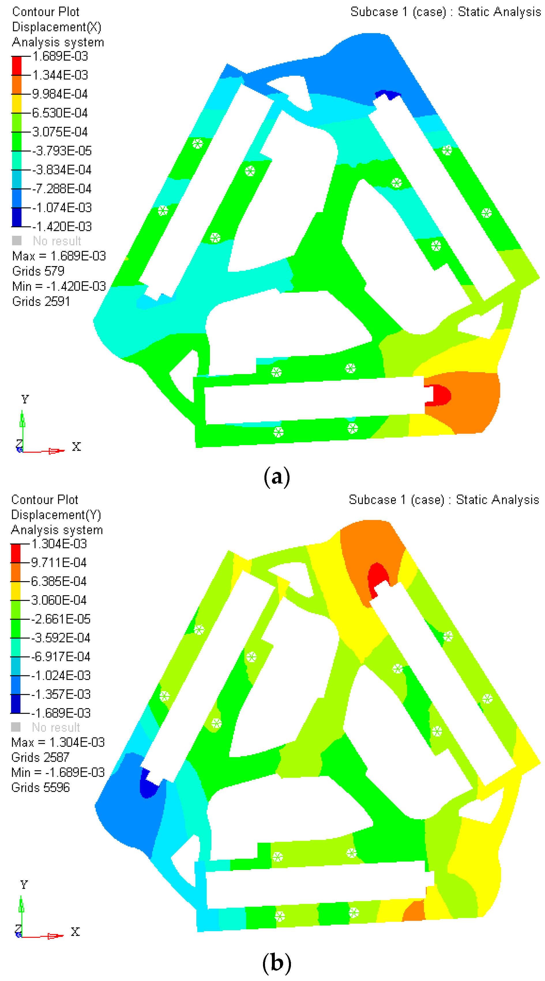
The experiment results indicate that the maximum static stress of the optimized mechanism decreases by 47% of the initial unoptimized mechanism, and the minimum static stress of the post-optimality increases too. The material static stress homogeneity distribution is obviously better than the original mechanism. The kinematostatic characteristics of optimized material structure with the prototype of 3-PRR planar fully CPMs are shown in
Figure 8, including the displacement of direction
x-
y and rotational directional
z respectively.
In this case, a static load of 1000 N is applied to each terminal of the optimized continuum structure with the prototype of 3-PRR planar fully CPM respectively. According to the mapping relation of input and output shown in
Figure 3, the output displacements of direction
x-
y and rotational directional
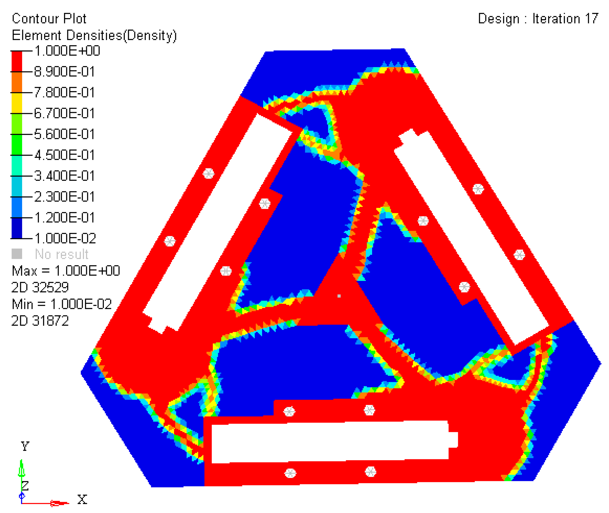
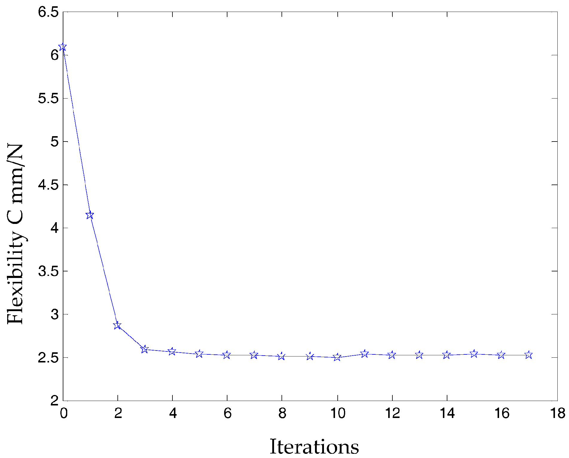
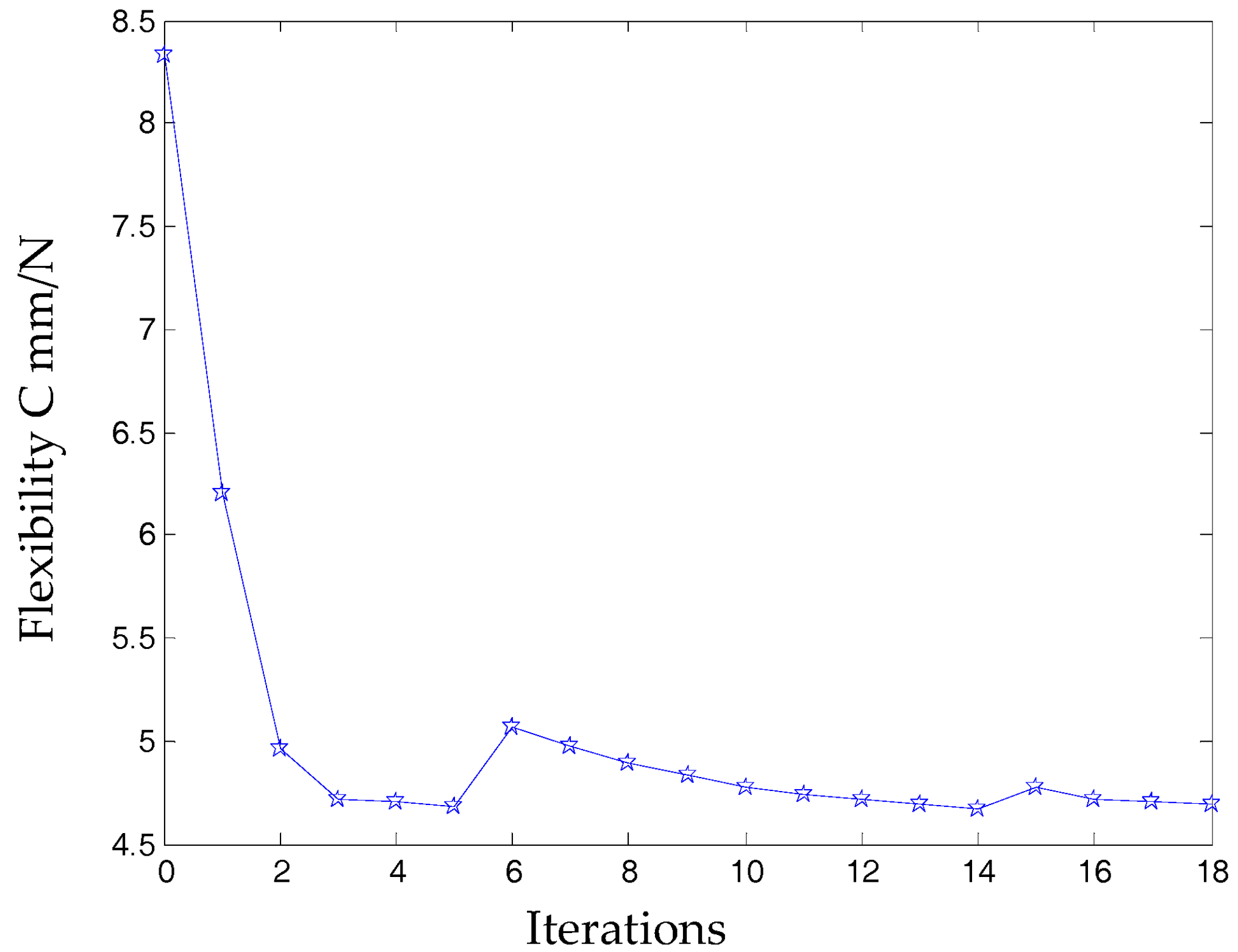
z are defined in the moving platform. After the topological optimization procedure with the flexibility minimizing as objective function and volume ratios as constraint conditions, the material element distribution and objective function iterations can be obtained as shown in
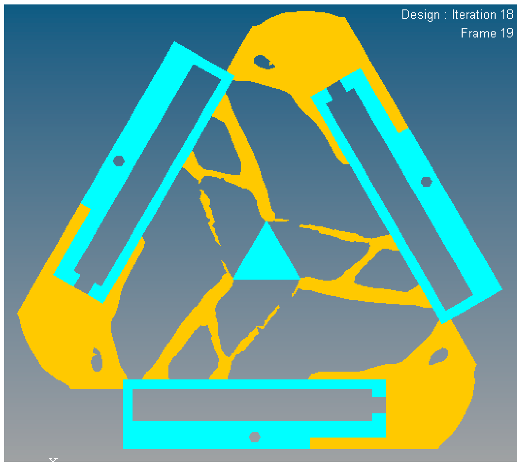
Figure 9 and
Figure 10, which converges after 18 iterations.
In
Figure 9, the nattier blue pieces are a no-design region representing boundary constraint conditions and the piezoelectric ceramic actuator fixed mount. The yellow pieces are constituted of reserved elements with material density of 1 or close to 1. After optimized iterations, the maximum and minimum flexibility parameters of the optimized material structure with the prototype of 3-PRR planar fully CPMs are shown in
Table 2.
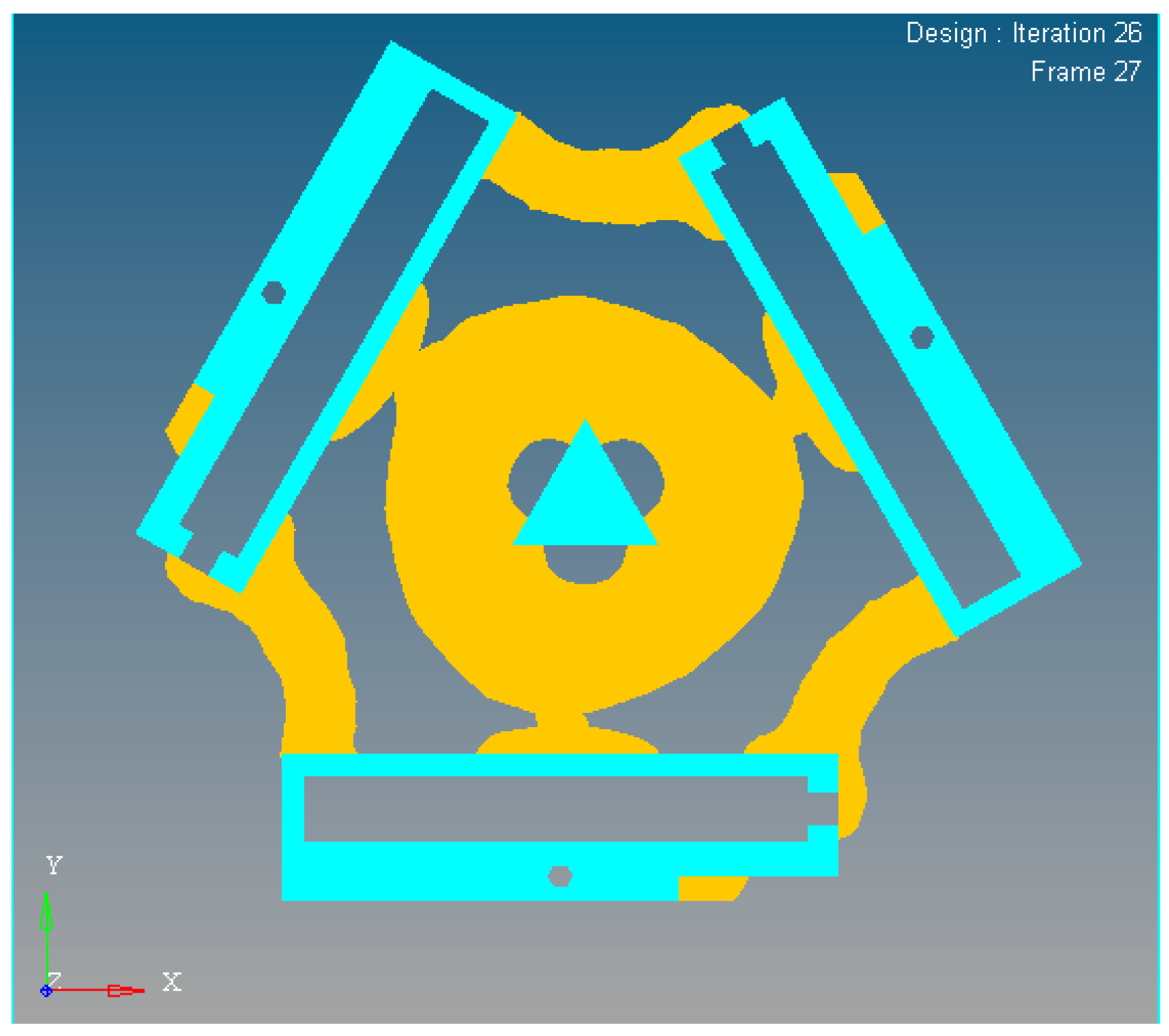
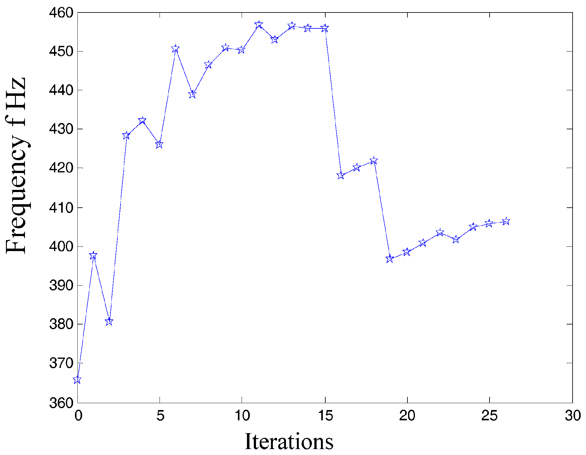
In the dynamics topological optimization iterations with first-order inherent frequency as objective function and volume ratios as constraint conditions shown as
Figure 3, the material element distribution and objective function iterative figures after 26 iterations optimization can be obtained, as shown in
Figure 11 and
Figure 12 respectively.
The first 3 orders’ inherent frequency parameters of optimization material structure with 3-PRR fully CPMs are shown in
Table 3.
The inherent vibration characteristic of mechanism is modal, and it is especially important for micro/nano manufacturing. The modal analysis of optimized continuum structure mechanism is carried out under the same input load case and boundary constraint conditions with the software tool of Optistruct
®. The integrated objective function is refined for the new optimized continuum structure mechanism with 3-PRR planar fully CPMs prototype. The first 6 modes of vibration modals are validated by self-weighted compromise programming with mean frequency method in user-defined function palette of Optistruct
®. With the prototype of multi-objective integrated topological optimization Function (23), the integrated objective function is described as (32) with the maximum and minimum flexibility of static single objective topology optimization listed in
Table 2 and maximum and minimum inherent frequency of the first 3 orders of dynamics single objective topology optimization listed in
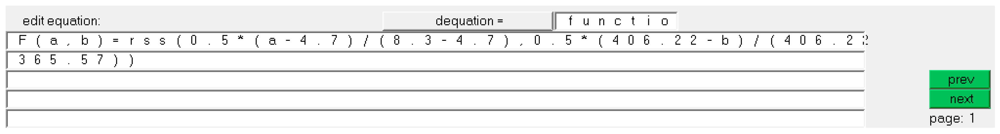
Table 3. The results of integrated objective functions are defined as (32)
where
i = 1 denotes single load case, we can define
ωi = 1, and the multi-objective design variables in topology optimization as flexibility
C1(
ρ) and 1-order inherent frequency
Λ(
ρ), the maximum flexibility
before static optimization with value of 8.3 mm/N, the minimum flexibility
after static optimization with value of 4.7 mm/N, the maximum inherent frequency
Λmax after dynamics optimization with value of 406.22 Hz, the minimum inherent frequency
Λmin before dynamics optimization with value of 365.57 Hz. According to the
rss function in Optistruct
®, the integrated multi-objective optimization function is imported in the
palette as shown in
Figure 13, substituting (a, b) to
C1(
ρ) and
Λmax respectively. So the minimum of integrated objective function
F(a, b) and volume ratio constraint conditions are solved in module of Optistruct
®, and the result is shown in Equation (33)
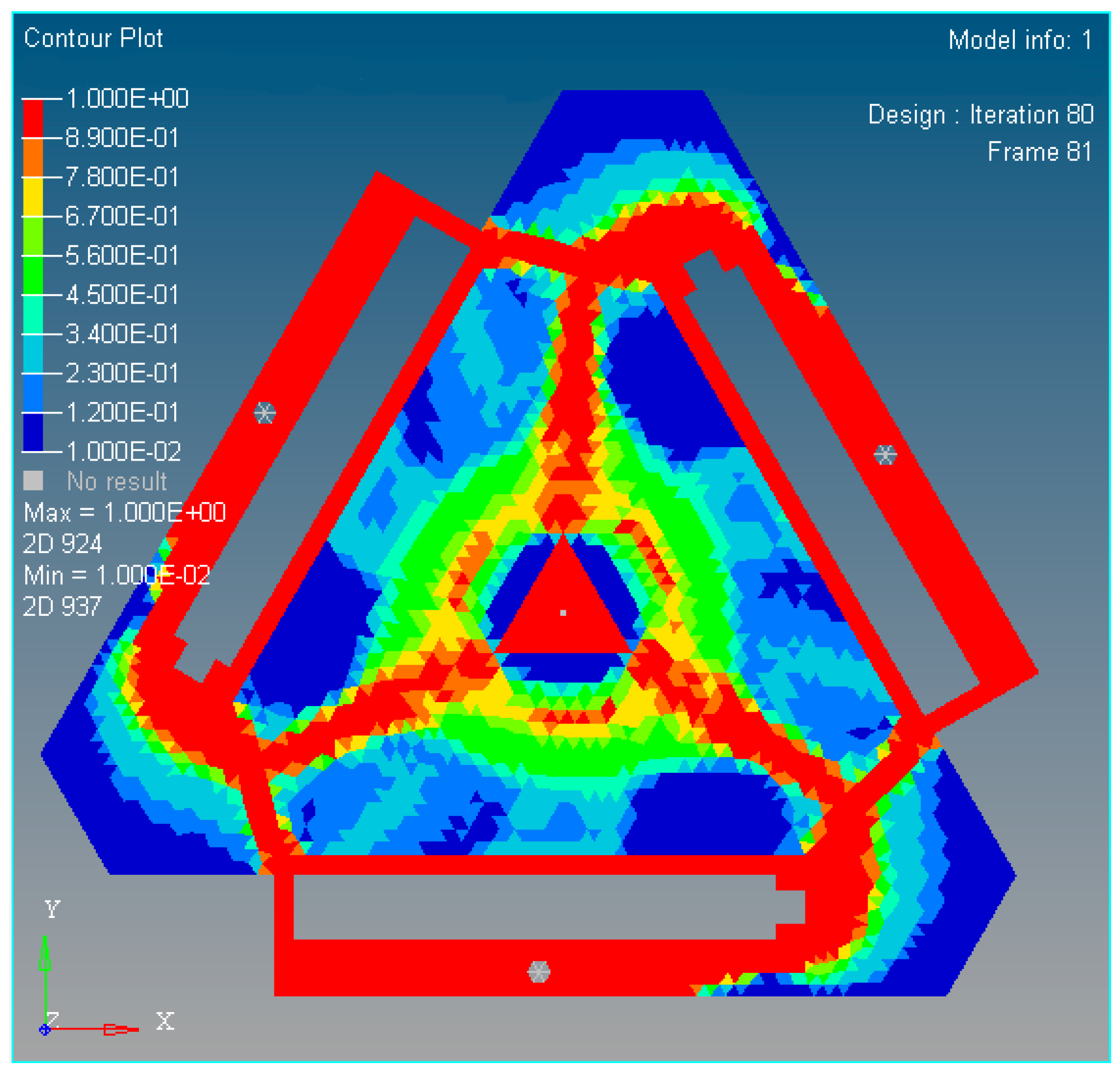
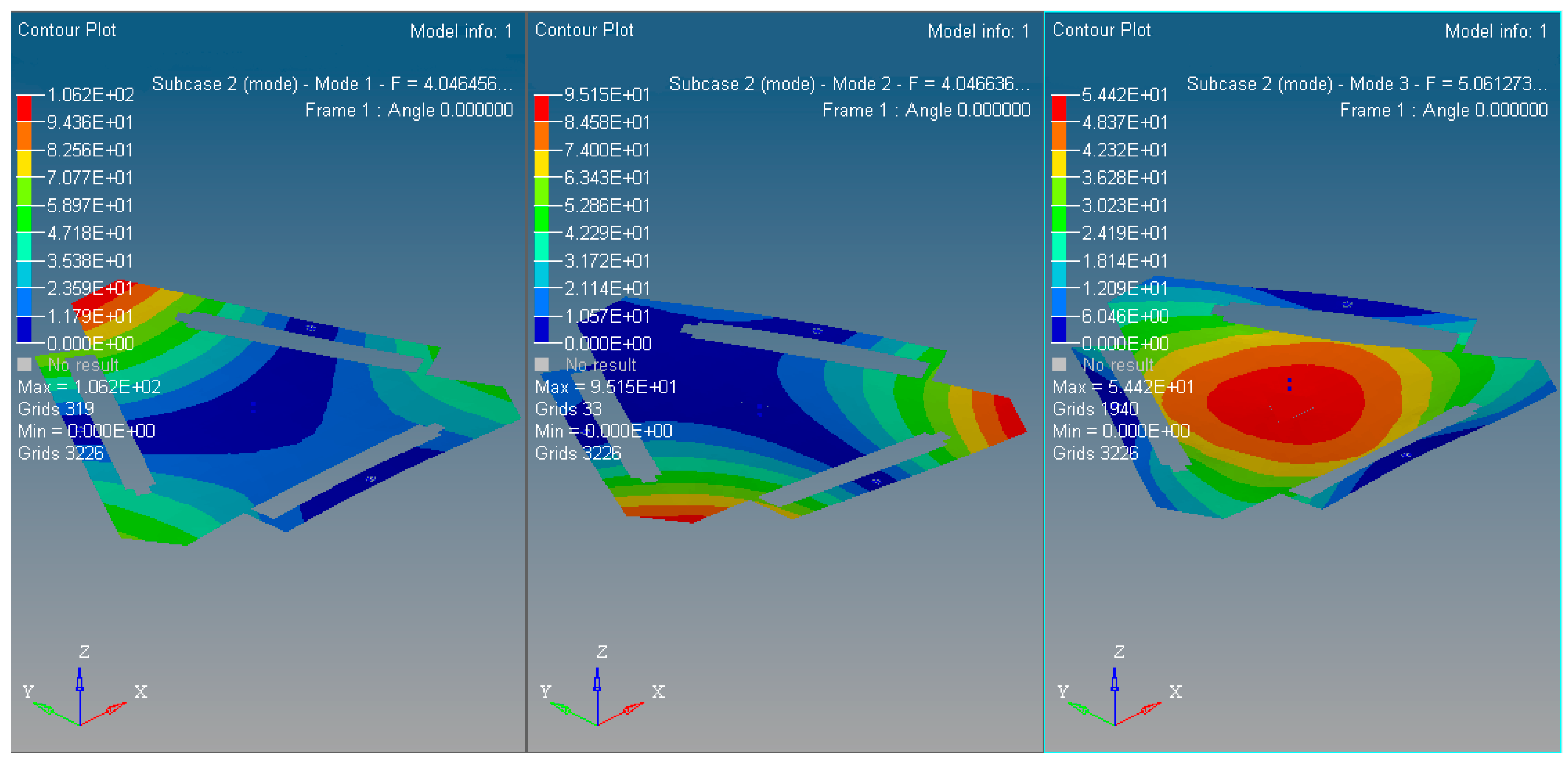
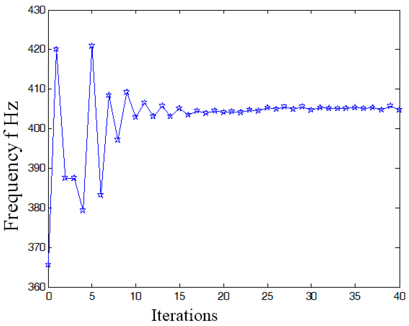
In summary, the optimized material structure model with prototype of 3-PRR planar fully CPMs carries out 40 optimizing iterations. The figures of multi-objective topology optimization results, the first 6 orders’ modal shapes, minimum flexibility iterations, and maximum frequency iterations can be obtained as shown in
Figure 14,
Figure 15,
Figure 16,
Figure 17 and
Figure 18. Comparing
Figure 18 of the first order inherent frequency iteration during the multi-objective topology optimization with that of
Figure 12, the iterations are more stable and easily convergent by mean frequency method.
Figure 14 shows the optimization result of flexibility
C, inherent frequency
Λ, and volume fraction
f. In
Figure 17, the flexibility increases as the material is gradually removed from the design domain. When the total volume of the remaining elements reaches the objective volume, the flexibility goes to 5.489 mm/N and the inherent frequency stabilizes at around 405.5 Hz shown in
Figure 18. It performs better than previous 3-PRR planar fully CPM limb-linked structure, which is attributed to the self-adjusting densities of all the elements in the optimization iterations.
The multi-objective optimization method obtains 40% of the initial volume (
f0 = 0.4) at the 40th iteration, and the volume fraction
f reaches 0.3836. When
f is equal to 0.55, the optimization only needs 26 iterations. Modal shapes of all the remaining elements are displayed in sub-graphs of
Figure 15 and
Figure 16. The minimum and maximum flexibilities, the first 3 inherent frequencies and modal shape calculated after optimization are shown in
Table 4.
The modal analysis results of the optimized material prototype as the 3-PRR planar fully CPMs show that low-order inherent frequency has been significantly improved more than the original status. This method can suppress the mechanism vibration and avoid losing precision positioning kinematics even resonance phenomenon. Meanwhile, the result of vibration-inherent frequency and relevant modal synthesis will provide a feasible basis for system synthesis (structural choice, dimension and topology optimization).


