Abstract
The liquid-phase exfoliation (LPE) method has been gaining increasing interest by academic and industrial researchers due to its simplicity, low cost, and scalability. High-intensity ultrasound energy was exploited to transform graphite to graphene in the solvents of dimethyl sulfoxide (DMSO), N,N-dimethyl formamide (DMF), and perchloric acid (PA) without adding any surfactants or ionic liquids. The crystal structure, number of layers, particle size, and morphology of the synthesized graphene samples were characterized by X-ray diffraction (XRD), atomic force microscopy (AFM), ultraviolet visible (UV–vis) spectroscopy, dynamic light scattering (DLS), and transmission electron microscopy (TEM). XRD and AFM analyses indicated that G-DMSO and G-DMF have few layers while G-PA has multilayers. The layer numbers of G-DMSO, G-DMF, and G-PA were determined as 9, 10, and 21, respectively. By DLS analysis, the particle sizes, polydispersity index (PDI), and zeta potential of graphene samples were estimated in a few micrometers. TEM analyses showed that G-DMSO and G-DMF possess sheet-like fewer layers and also, G-PA has wrinkled and unordered multilayers.
1. Introduction
Graphene is a versatile nanomaterial with a wide range of chemical, environmental, medical, industrial, and electronical applications by means of its remarkable thermal conductivity (above 3000 W m K−1), superior mechanical properties with a Young’s modulus of 1 TPa, an extraordinary large specific surface area (2620 m2 g−1), intrinsic strength of 130 GPa, and an extremely high electronic conductivity (room-temperature electron mobility of 2.5 × 105 cm2 V−1 s−1) [1,2,3]. This combination of spectacular properties enables its utilization in the production of different devices, such as electronics with high-speed and radio-frequency logic, sensors, membranes, composites with high thermal and electrical conductivity, displays with superior transparency and flexibility, solar cells, coatings, ultrathin carbon films, electronic circuits, etc. [4].
Few-layered graphene has been synthesized by numerous methods including mechanical cleavage, liquid-phase exfoliation, gas-phase synthesis, Hummers’ method, unrolling of multi-walled carbon nanotubes (MWCNTs), chemical vapor deposition (CVD), epitaxial growth, and electrochemical reaction [2,5,6,7,8,9,10,11,12,13,14,15]. However, these methods have some drawbacks, such as low yield ratio, high-energy consumption, the use of expensive substrates, as well as the difficulty of obtaining a high-quality product. Scientists have studied the development of more efficient synthesis methods apart from the most popular Hummers’ method employing the oxidative exfoliation of natural graphite by harsh acid treatments. The final products attained by Hummers’ method have many functional groups, such as hydroxyls, carbonyls, and carboxyls, which cannot be completely removed by additional reduction and annealing treatments [6,16,17]. Additionally, the oxidation-reduction processes of Hummers’ method disrupt the original honeycomb structure of graphene [18]. This deteriorated structure reduces the electronical and mechanical properties of the synthesized final graphene products [19,20]. For this reason, selection of the appropriate solvent and process parameters has a critical importance in order to obtain the graphene with a well-arranged structure. Liquid-phase exfoliation (LPE) is one of the most feasible methods for industrial production of graphene through its scalability and low cost. A highly stable dispersion of mono/few-layered graphene products with a defect-free honeycomb structure has been synthesized by LPE of graphite by applying different techniques such as shear mixing, microwave irradiation, or sonication [21]. The application of the LPE method is especially significant for the electronics industry which requires defect-free graphene products without oxide groups [22].
The LPE technique is based on the exfoliation of graphite intercalated compounds in an appropriate solvent. In this technique, there are three subsequent steps: (1) dispersion of graphite in a solvent, (2) exfoliation, and (3) purification [23]. For the intercalation of the solvent molecules, the Van der Waals forces between the graphite layers are overcome by the application of the external driving force, such as ultrasound energy [24]. Then, individual layers start to slip out from the layered structure of graphite under the effect of shear force. By this fragmentation, thinner graphene flakes with a small lateral size can be achieved. The utilization of ultrasound energy in various types of chemical processes relies on the acoustic cavitation in a liquid. The main elements of the acoustic cavitation are the formation, development, and collapse of cavitation bubbles. Steam bubbles emerge due to the pressure drop in some parts of liquid. On the other hand, the rise in pressure and temperature causes the extinction of the cavities. When the liquid is subjected to the ultrasound energy, localized hot points appear with high temperature and pressure [18].
The efficiency of the ultrasound energy is determined by the ultrasound application conditions and the type of ultrasound device. There are two types of ultrasound generators: horn type and bath type. Epoxy/graphene nanocomposites synthesized by using the horn-type device demonstrate higher modulus and flexural strength properties than that of the samples produced via the bath-type device [18]. The reason for obtaining better properties with the horn-type device is the direct immersion of the probe into the sonication liquid. This direct sonication results in turbulent flow conditions and acoustic streaming in suspensions, which prevents the agglomeration of the nanoparticles. In the case of graphene synthesis by the LPE method with ultrasonication, the traditional bath-type sonicator is inadequate to produce intense cavitation necessary for the efficient exfoliation of graphite without chemicals, such as ionic liquids and surfactants [18].
The properties of the liquid establishing the environment for the chemical processes have a great impact on obtaining a stable graphite-solvent dispersion [25]. Many studies were conducted to investigate the most convenient solvent type and optimum process conditions for the synthesis of graphene by ultrasonication [26,27,28]. Graphite is easily exfoliated in polar aprotic organic solvents due to its hydrophobic character. In this study, polar aprotic dimethyl sulfoxide (DMSO) and dimethyl formamide (DMF) were used for exfoliation of graphite as the sonication medium without addition of any surfactants or ionic liquids. Additionally, these solvents prevent the inverse segregation and micelle cumulation of graphenes by exposure to high-intensity ultrasound energy [29]. The mechanism of the graphite dispersions in solvents of DMSO and DMF is ascribed to restricted solvent layer near the graphene surface blocking the aggregation of graphene layers because of the existence of sterics in the chemical structure of these solvents [30]. As the third sonication solvent, perchloric acid (PA) was chosen due to the benefit of being a highly effective self-intercalating agent. Although PA was utilized at high concentrations for sonication, it still minimizes the defects in the honeycomb lattice of graphene [31,32,33]. When PA is compared to the other strong acids, such as H2SO4 and HNO3, it requires no excess heating process and no use of oxidizers [34,35]. All these solvents (Figure 1) used in this study are capable of successful exfoliation of the graphite and prevention of the graphene transformation back to a graphite structure. The perchlorate ions between the graphite layers separate them by the crystal delamination under sonication forming an electrolyte including small graphene flakes [36,37].
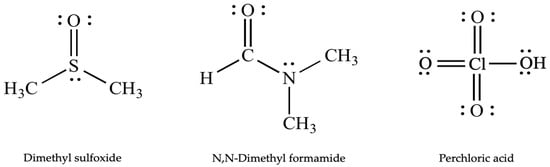
Figure 1.
Lewis structure of the solvents used as liquid medium in the exfoliation of graphite.
In the present study, we introduced one-pot synthesis of graphene via ultrasonication of graphite in different organic solvents without using ionic liquids or surfactants. The characterization of synthesized graphene samples was performed by XRD, AFM, UV-vis, DLS, and TEM analyses.
2. Experimental
2.1. Materials
Graphite fine powder (extra pure) and commercial graphene (CG) were purchased from, Asbury Inc., Asbury, NJ, USA and XG Sciences, Lansing, MI, USA, respectively. Dimethyl sulfoxide (DMSO) (Merck), N,N-dimethylformamide (DMF) (Merck), and perchloric acid 70−72% (PA) (Merck) were of analytical grade and used as received. CG was used as the control sample in order to compare the precision and purity of the synthesized graphene products.
2.2. Method
First, 0.3 g graphite were dispersed in a 50-mL solvent, such as DMSO, DMF, and PA. The prepared dispersions were sonicated for 3 h by using BANDELIN® HD 2200 SONOPULS equipped with a vs. 190 T sonotrode made of titanium alloy, 200 W, 50% amplitude (Figure 2). Afterwards, these dispersions were subjected to Elektromag, M 4812 P for 1 h at 3000 rpm in order to remove the unexfoliated graphite particles. Then, the large aggregates were settled down, the supernatant part of the samples was decanted, and then collected in separate vials.
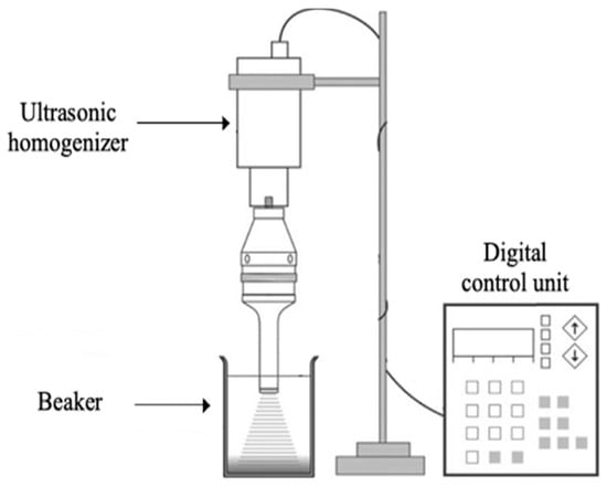
Figure 2.
Ultrasonic treatment unit.
2.3. Characterization
X-ray diffraction (XRD) was conducted by depositing the samples onto glass pieces (0.7 × 0.7 mm2) and their XRD spectra were determined by a Rigaku D-Max 2200 Series device equipped with Cu-Kα radiation (λ = 1.54 Å) at a scanning rate of 3° per minute. Its tube voltage and current were 40 kV and 40 mA, respectively. Samples for AFM were prepared by dropping the graphene dispersions onto glass pieces (0.7 × 0.7 mm2) and measurements were carried out in contact (tapping) mode, with 10.00 μm scan size, and 20.35 Hz scan rate by using a Digital Instruments Nanoscope. Ultraviolet-visible (UV-vis) spectroscopy analyses were done by a Perkin Elmer Precisely Lambda 35 UV-vis Spectrometer in the region between 200–800 nm wavelengths. In order to elucidate the particle size distribution, polydispersity index (PDI) and zeta potential analyses were carried out by the dynamic light scattering (DLS) method through a Malvern Zetasizer Nano ZS Laser particle size distribution meter. The structural and morphological properties were determined by a Hitachi HT7800 model transmission electron microscope (TEM) operating at 120 kV.
3. Results and Discussion
The exfoliation mechanism of graphite by the sonochemical process using a horn-type device is given in Figure 3. This type of sonicator produces high-intensity ultrasound energy, which enables stable micromechanical exfoliation of graphite. Additionally, the horn-type sonicator provides the synthesis of graphene with minor functional groups and flat and defect-free morphologies. The stable dispersion of graphene into solvents can be provided by sonication that builds cavitation shear stress in the solvent. The sonication time and power can adjust the concentration of the dispersion.
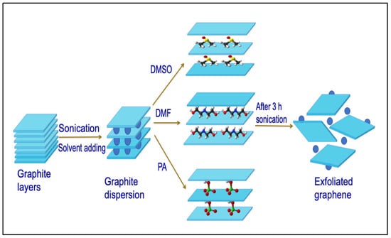
Figure 3.
The exfoliation mechanism of the graphite to graphene.
The stable homogeneous dispersion of graphite can be achieved in solvents, such as DMSO, DMF, and PA, possessing similar surface tensions close to that of graphene (~68 mJ/m2) [38,39]. The surface energies of DMSO, DMF, and PA are 43.5, 37.1, and 70.0 mJ/m2, respectively. When the surface energies of the dispersed phase and dispersant are close to each other, the enthalpy of mixing is diminished, resulting in a stable dispersion of graphite. The crystal structure and the layer numbers of the natural graphite and the graphene products (G-DMSO, G-DMF, and G-PA) were determined by XRD analysis given in Figure 4. It is well-known that the peak at 2θ° = 26.5 indicates the graphene characteristic structure. The graphene peak has a lower intensity, which is decreased compared to graphite, showing that the graphite tends to have an amorphous crystal structure of graphene [40]. In the XRD pattern of graphite, the (002) crystal plane of graphite was evident, with a d-spacing of 3.4 Å, which is typical for graphite. After intercalation of graphite, the produced samples showed a d-spacing of 3.5, 3.3, and 3.3 Å for G-DMSO, G-DMF and G-PA, respectively. The peak (002) crystal plane of graphenes had an average value of 3.4 Å, proving the formation of graphenes with few-layered structures.
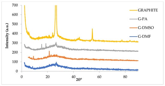
Figure 4.
XRD results of synthesized graphene products.
The thickness of graphene products was estimated by applying Scherrer’s equation, which is stated as D002 = Kλ/Bcos θ. D002, where K, λ, B, and θ are the thickness of the graphene, a constant based on the crystal shape (0.89), the wavelength of the X-ray (0.15406 nm), the full width half maximum (FWHM) of the characteristic peak of graphene, and the scattering angle, respectively [41,42]. The number of layers was calculated by the following equation: N = D002/d002, where d002 is the interlayer distance [43,44]. The calculated layer numbers of G-DMSO, G-DMF, and G-PA are 9, 10, and 20, respectively. Although the layer numbers of G-DMSO and G-DMF were very close to each other, G-PA gave a higher layer number. This higher layer number value may be explained by the inverse segregation of graphene particles synthesized in PA.
The thickness and surface roughness values of G-DMSO, G-DMF, and G-PA were determined via AFM analysis shown in Figure 5. Roughness average (Ra) is defined as the arithmetic mean of the absolute values of the height alterations from the mean line along the profile. The square root of the arithmetic mean surface roughness (Rq) is also described to take into account the big peaks and valleys [45]. Additionally, the roughness mean square (RMS) is calculated by using height values of microscopic peaks and valleys. As seen from Figure 5, the Ra values are 2.94, 6.34, and 15.45 nm, whereas the Rq values are 3.47, 8.05, and 17.26 nm for G-DMSO, G-DMF, and G-PA, respectively. Furthermore, the RMS values are determined as 5.68, 8.84, and 19.29 nm for G-DMSO, G-DMF, and G-PA, respectively.
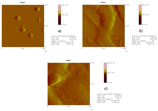
Figure 5.
The Atomic Force Microscopy (AFM) images of (a) Graphene product obtained in dimethyl sulfoxide (G-DMSO), (b) Graphene product obtained in N,N-dimethyl formamide (G-DMF), and (c) Graphene product obtained in perchloric acid (G-PA) drop casted onto a glass piece showing the homogeneous structure of the pristine graphene nanosheets.
In order to confirm the number of graphene layers, AFM results were exploited as well. The following equation was used for the calculation of layer numbers: N = (tmeasured − 0.4)/0.335, where tmeasured is the vertical distance. The value of 0.335 nm is the thickness of the single-layer graphene. Since the mica was used as a substrate material in the AFM measurements, the height was accepted as 0.4 nm [46]. The thickness (tmeasured) values of the graphene samples were measured as 1.64, 2.15, and 7.28 nm for G-DMSO, G-DMF, and G-PA, respectively. The number of layers was calculated from the aforementioned equation as 3.69 ≅ 4, 5.22 ≅ 5, and 21.05 ≅ 21 for G-DMSO, G-DMF, and G-PA, respectively. When all the results were assessed, the roughness and the layer number values of G-DMSO and G-DMF are smaller than that of G-PA. The layer numbers of graphene products obtained from XRD agree with those estimated from the AFM. It can be inferred from these findings that while G-DMSO and G-DMF include fewer layers, G-PA has a multi-layered structure. In the case of preparation of graphene in PA, the RMS and layer number are 19.3 and 21.0 nm, respectively. For the sample of G-DMSO, the RMS and layer number are 5.7 and 4.0 nm, respectively. The multilayered specimen of G-PA has a higher RMS value, which is in accordance with the literature [47]. It is believed that the combined effect of high-power ultrasound energy and strong acidity of PA might trigger the formation of some functionalities on the graphene, leading to an increase in the surface roughness. Additionally, the reason for the higher thickness may be due to the out-of-plane rippling behavior of graphene [48].
In order to clarify the graphene structure, the UV-vis spectra of the graphene dispersions were recorded as seen in Figure 6. The synthesized graphene products were characterized by comparing the properties with that of CG. The graphene samples labeled as G-DMSO, G-DMF, and G-PA, showed a peak at the 265-nm wavelength referring to sp2 C = C bonds [49].
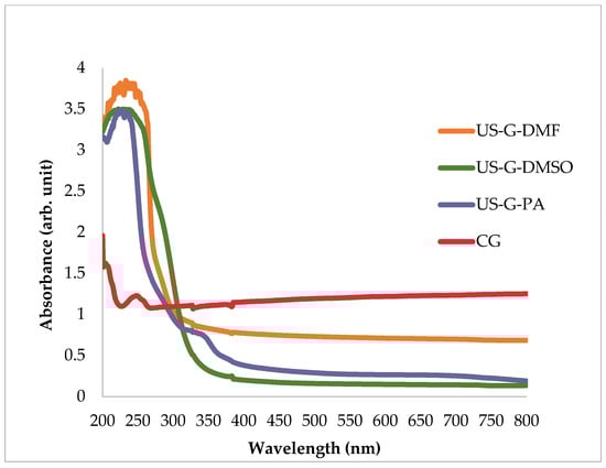
Figure 6.
UV-vis spectra of CG, G-DMSO, G-DMF, and G-PA products.
Next, the dynamic light scattering (DLS) technique, which gives the apparent size of the graphene samples in the aqueous dispersion, was applied to investigate the particle size [50]. The size distribution results are presented in Figure 7.
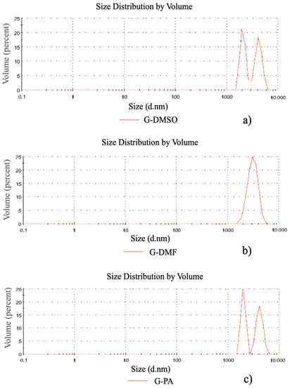
Figure 7.
Particle size analysis results of synthesized samples, (a) G-DMSO, (b) G-DMF, (c) G-PA.
Table 1 gives the particle size diameters, polydispersity indexes, and zeta potentials. As seen in Table 1, the Z-average hydrodynamic radius (Rh) values of G-DMSO, G-DMF, and G-PA are 6938 ± 408, 3846 ± 18.5, and 7137 ± 2.5 nm, respectively. These results are parallel to the previous studies, which reported graphene samples with a few micrometers of Rh with a less defected structure. The graphene with these particle sizes is promising and favorable for applications in the electronics industry [28,51]. According to the measurements performed by the DLS technique, the particle domain sizes of G-DMSO and G-PA samples demonstrated bimodal distributions, with PDI values of 0.692 ± 0.308 and 0.629 ± 0.150, respectively. Nevertheless, the smallest particle size and PDI value were obtained as 3846 ± 18.5 and 0.307 ± 0.056, respectively, for the graphene sample exfoliated in DMF solvent. For G-DMSO, the major part of the material was detected at 2055 nm and the rest of the material was observed at 4103 nm. The majority of the material in the G-PA sample shows an average diameter of 1990 nm. The smaller concentration of particles presents an average size of about 4074 nm.

Table 1.
Dynamic light scattering analysis of the obtained graphene samples.
As it is seen from Table 1, zeta potentials (mV) are measured as −8.76 ± 15.4, −11.7 ± 3.38, and −3.49 ± 4.09 for G-DMSO, G-DMF and G-PA, respectively. For all the sonication solvents, zeta potential values were negative due to the interfacial Lewis charge transfer between the graphene particles and the solvent molecules [30]. Figure 8 illustrates the TEM images of graphene products of G-DMSO, G-DMF, and G-PA.
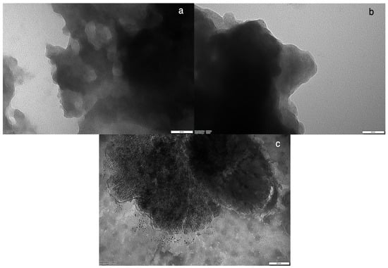
Figure 8.
TEM images of graphene layers in sample (a) G-DMSO, (b) G-DMF, and (c) G-PA. Scale bar: (a) 50 nm, (b) 50 nm, and (c) 200 nm.
TEM analysis revealed that G-DMSO and G-DMF have fewer layers while G-PA has multilayers. The light- and dark-colored parts (Figure 8a,b) represent the few-layered structures at the edges of the sample and the multilayered agglomerates at the surface, respectively. Additionally, Figure 8a,b exhibit the sheet-like flakes of the graphene structure overlapping at some parts. Figure 8c presents a wrinkled and unordered structure of G-PA, which was synthesized by excessive cavitation in PA. Due to the high acidic character of PA, crumbled structure, and deficiencies, low-quality properties were observed on the surface morphology of the sample. Moreover, the dark-colored parts on the image of G-PA display the contamination arising from the residual solvent [52].
4. Conclusions
In summary, the ultrasound assisted LPE method was used for the synthesis of graphene in the solvents of DMSO, DMF, and PA. According to the XRD results, the layer numbers of the samples labelled as G-DMSO, G-DMF, and G-PA were estimated as 9, 10, and 20, respectively. The UV-vis spectra of all the samples showed a peak at the 265-nm wavelength, indicating the sp2 C = C bonds of graphene. Additionally, the results of AFM showed that the layer numbers were 4, 5, and 21. The zeta potentials (mV) were measured as −8.76 ± 15.4, −11.7 ± 3.38, and −3.49 ± 4.09 for G-DMSO, G-DMF, and G-PA, respectively, whereas the Z-average hydrodynamic radius (Rh) was 6930 ± 408, 3846 ± 18.5, and 7137 ± 2.5 nm for G-DMSO, G-DMF, and G-PA, respectively. XRD, AFM, and TEM revealed that G-DMSO and G-DMF contain few layers while G-PA has a multilayer structure. Finally, it can be concluded that DMSO is a promising solvent for the one-pot synthesis of few-layered graphene by the LPE method without using any surfactants or ionic liquids.
Author Contributions
Conceptualization, B.G., Ç.T.-Y. and M.B.; methodology, B.G., Ç.T.-Y. and M.B.; software, B.G., Ç.T.-Y. and M.B.; validation, B.G., Ç.T.-Y. and M.B.; formal analysis, B.G., Ç.T.-Y. and M.B..; investigation, B.G., Ç.T.-Y. and M.B.; resources, B.G., Ç.T.-Y. and M.B.; data curation, B.G., Ç.T.-Y. and M.B.; writing—original draft preparation, B.G., Ç.T.-Y. and M.B.; writing—review and editing, B.G., Ç.T.-Y. and M.B.; visualization, B.G., Ç.T.-Y. and M.B.; supervision, B.G., Ç.T.-Y. and M.B.; project administration, B.G., Ç.T.-Y. and M.B.; funding acquisition, B.G., Ç.T.-Y. and M.B. All authors have read and agreed to the published version of the manuscript.
Funding
This work has been partially supported by Research Fund of the Gebze Technical University (project no. 2018-A105-55)
Acknowledgments
This work has been partially supported by Research Fund of the Gebze Technical University (project no. 2018-A105-55). The authors also acknowledge the Materials Science and Engineering Department of Gebze Technical University for providing AFM and DLS measurements.
Conflicts of Interest
The authors declare no conflict of interest.
References
- Geim, A.K.; Novoselov, K.S. The rise of graphene. Nat. Mater. 2007, 6, 183–191. [Google Scholar] [CrossRef]
- Novoselov, K.S.; Geim, A.K.; Morozov, S.V.; Jiang, D.; Zhang, Y.; Dubonos, S.V.; Grigorieva, I.V.; Firsov, A.A. Electric field effect in atomically thin carbon films. Science 2004, 306, 666–669. [Google Scholar] [CrossRef]
- Georgakilas, V.; Otyepka, M.; Bourlinos, A.B.; Chandra, V.; Kim, N.; Kemp, K.C.; Hobza, P.; Zboril, R.; Kim, K.S. Functionalization of graphene: Covalent and non-covalent approaches, derivatives and applications. Chem. Rev. 2012, 112, 6156–6214. [Google Scholar] [CrossRef]
- Allen, M.J.; Tung, V.C.; Kaner, R.B. Honeycomb Carbon: A Review of Graphene. Chem. Rev. 2010, 110, 132–145. [Google Scholar] [CrossRef] [PubMed]
- Zhang, X.; Coleman, A.C.; Katsonis, N.; Browne, W.R.; van Wees, B.J.; Feringa, B.L. Dispersion of Graphene in Ethanol Using a Simple Solvent Exchange Method. Chem. Commun. 2010, 46, 7539–7541. [Google Scholar] [CrossRef] [PubMed]
- Stankovich, S.; Dikin, D.A.; Piner, R.D.; Kohlhaas, K.A.; Kleinhammes, A.; Jia, Y.; Wu, Y.; Nguyen, S.T.; Ruoff, R.S. Synthesis of graphene-based nanosheets via chemical reduction of exfoliated graphite oxide. Carbon 2007, 45, 1558–1565. [Google Scholar] [CrossRef]
- Compton, O.C.; Nguyen, S.B.T. Graphene Oxide, Highly Reduced Graphene Oxide, and Graphene: Versatile Building Blocks for Carbon-Based Materials. Small 2010, 6, 711–723. [Google Scholar] [CrossRef] [PubMed]
- Qi, X.; Pu, K.-Y.; Zhou, X.; Li, H.; Liu, B.; Boey, F.; Huang, W.; Zhang, H. Conjugated-Polyelectrolyte-Functionalized Reduced Graphene Oxide with Excellent Solubility and Stability in Polar Solvents. Small 2010, 21, 663–669. [Google Scholar] [CrossRef]
- Vadahanambi, S.; Jung, J.-H.; Kumar, R.; Kim, H.-J.; Oh, I.-K. An ionic liquid-assisted method for splitting carbon nanotubes to produce graphene nano-ribbons by microwave radiation. Carbon 2013, 53, 391–398. [Google Scholar] [CrossRef]
- Kleinschmidt, A.C.; Donato, R.K.; Perchacz, M.; Benes, H.; Stengl, V.; Amico, S.C.; Schrekker, H.S. “Unrolling” multi-walled carbon nanotubes with ionic liquids: Application as fillers in epoxy-based nanocomposites. RSC Adv. 2014, 4, 43436. [Google Scholar] [CrossRef]
- Liu, Q.; Fujigaya, T.; Nakashima, N. Graphene unrolled from ‘cup-stacked’ carbon nanotubes. Carbon 2012, 50, 5421–5428. [Google Scholar] [CrossRef]
- Emtsey, K.V.; Bostwick, A.; Horn, K.; Jobst, J.; Kellogg, G.L.; Ley, L.; McChesney, J.L.; Ohta, T.; Reshanov, S.A.; Rohrl, J.; et al. Towards Wafer-Size Graphene Layers by Atmospheric Pressure Graphitization of Silicon Carbide. Nat. Mater. 2009, 8, 203–207. [Google Scholar] [CrossRef] [PubMed]
- Li, X.; Cai, W.; An, J.; Kim, S.; Nah, J.; Yang, D.; Piner, R.; Velamakanni, A.; Jung, I.; Tutuc, E.; et al. Large-area Synthesis of High-Quality and Uniform Graphene Films on Copper Foils. Science 2009, 324, 1312–1314. [Google Scholar] [CrossRef] [PubMed]
- Lee, J.-W.; Kim, M.; Na, W.; Hong, S.M.; Koo, C.M. Fabrication of high quality graphene nanosheets via a spontaneous electrochemical reaction process. Carbon 2015, 91, 527–534. [Google Scholar] [CrossRef]
- Dato, A.; Radmilovic, V.; Lee, Z.; Phillips, J.; Frenklach, M. Substrate-free Gas-Phase Synthesis of Graphene Sheets. Nano Lett. 2008, 8, 2012–2016. [Google Scholar] [CrossRef]
- Li, X.; Zhang, G.; Bai, X.; Sun, X.; Wang, X.; Wang, E.; Dai, H. Highly conducting graphene sheets and Langmuir–Blodgett films. Nat. Nanotechnol. 2008, 3, 538–542. [Google Scholar] [CrossRef]
- Ambrosi, A.; Chua, C.K.; Bonanni, A.; Pumera, M. Electrochemistry of Graphene and Related Materials. Chem. Rev. 2014, 114, 7150–7188. [Google Scholar] [CrossRef]
- Suslick, K.S. Sonochemistry. Science 1990, 247, 1439–1445. [Google Scholar] [CrossRef]
- Guo, S.; Dong, S. Graphene nanosheet: Synthesis, molecular engineering, thin film, hybrids, and energy and analytical applications. Chem. Soc. Rev. 2011, 40, 2644–2672. [Google Scholar] [CrossRef]
- Rao, C.N.R.; Sood, A.K.; Subrahmanyam, K.S.; Govindaraj, A. Graphene: The New Two-Dimensional Nanomaterial. Angew. Chem. Int. Ed. 2009, 48, 7752–7777. [Google Scholar] [CrossRef]
- Lotya, M.; King, P.J.; Khan, U.; De, S.; Coleman, J.N. High-Concentration, Surfactant-Stabilized Graphene Dispersions. ACS Nano 2010, 4, 3155–3162. [Google Scholar] [CrossRef] [PubMed]
- Lotya, M.; Hernandez, Y.; King, P.J.; Smith, R.J.; Nicolosi, V.; Karlsson, L.S.; Blighe, F.M.; De, S.; Wang, Z.M.; McGovern, I.T.; et al. Liquid Phase Production of Graphene by Exfoliation of Graphite in Surfactant/Water Solutions. J. Am. Chem. Soc. 2009, 131, 3611–3620. [Google Scholar] [CrossRef] [PubMed]
- Ciesielski, A.; Samori, P. Graphene via sonication assisted liquid-phase exfoliation. Chem. Soc. Rev. 2014, 43, 381–398. [Google Scholar] [CrossRef] [PubMed]
- Xu, H.; Zeiger, B.W.; Suslick, K.S. Sonochemical synthesis of nanomaterials. Chem. Soc. Rev. 2013, 42, 2555–2567. [Google Scholar] [CrossRef] [PubMed]
- Whitener, K.E., Jr.; Sheehan, P.E. Graphene synthesis. Diamond Relat. Mater. 2014, 46, 25–34. [Google Scholar] [CrossRef]
- Yi, M.; Shen, Z. A review on mechanical exfoliation for the scalable production of graphene. J. Mater. Chem. A 2015, 3, 11700–11715. [Google Scholar] [CrossRef]
- Blake, P.; Brimicombe, P.D.; Nair, R.R.; Booth, T.J.; Jiang, D.; Schedin, F.; Ponomarenko, L.A.; Morozov, S.V.; Gleeson, H.F.; Hill, E.W.; et al. Graphene-based liquid crystal device. Nano Lett. 2008, 8, 1704–1708. [Google Scholar] [CrossRef]
- Hernandez, Y.; Nicolosi, V.; Lotya, M.; Blighe, F.M.; Sun, Z.; De, S.; McGovern, I.T.; Holland, B.; Byrne, M.; Gun’ko, Y.K.; et al. High-yield production of graphene by liquid-phase exfoliation of graphite. Nat. Nanotechnol. 2008, 3, 563–568. [Google Scholar] [CrossRef]
- Štengl, V. Preparation of graphene by Using an Intense Cavitation Field in a Pressurized Ultrasonic Reactor. Chem. Eur. J. 2012, 18, 14047–14054. [Google Scholar] [CrossRef]
- Johnson, D.W.; Dobson, B.P.; Coleman, K.S. A manufacturing perspective on graphene dispersions. Curr. Opin. Colloid Interface Sci. 2015, 20, 367–382. [Google Scholar] [CrossRef]
- Schnyder, B.; Alliata, D.; Kötz, R.; Siegenthaler, H. Electrochemical intercalation of perchlorate ions in HOPG: An SFM/LFM and XPS study. Appl. Surf. Sci 2001, 173, 221–232. [Google Scholar] [CrossRef]
- Beck, F.; Junge, H.; Krohn, H. Graphite intercalation compounds as positive electrodes in galvanic cells. Electrochim. Acta 1981, 26, 799–809. [Google Scholar] [CrossRef]
- Zhang, J.; Wang, E. STM investigation of HOPG superperiodic features caused by electrochemical pretreatment. J. Electroanal. Chem. 1995, 399, 83–89. [Google Scholar] [CrossRef]
- Wei, X.H.; Liu, L.; Zhang, J.X.; Shi, J.L.; Guo, Q.G. The preparation and morphology characteristics of exfoliated graphite derived from HClO4–graphite intercalation compounds. Mater. Lett. 2010, 64, 1007–1009. [Google Scholar] [CrossRef]
- Wei, X.H.; Liu, L.; Zhang, J.X.; Shi, J.L.; Guo, Q.G. HClO4–graphite intercalation compound and its thermally exfoliated graphite. Mater. Lett. 2009, 63, 1618–1620. [Google Scholar] [CrossRef]
- Nicolosi, V.; Chhowalla, M.; Kanatzidis, M.G.; Strano, M.S.; Coleman, J.N. Liquid Exfoliation of Layered Materials. Science 2013, 340, 1226419. [Google Scholar] [CrossRef]
- Catheline, A.; Ortolani, L.; Morandi, V.; Melle-Franco, M.; Drummond, C.; Zakri, C.; Pénicaud, A. Solutions of Fully exfoliated Individual Graphene Flakes in Low Boiling Point Solvents. Soft Matter 2012, 8, 7882–7887. [Google Scholar] [CrossRef]
- Coleman, J.N. Liquid Exfoliation of Defect-Free Graphene. Acc. Chem. Res. 2013, 46, 14–22. [Google Scholar] [CrossRef]
- Wang, S.; Zhang, Y.; Abidi, N.; Cabrales, L. Wettability and Surface Free Energy of Graphene Films. Langmuir 2009, 25, 11078–11081. [Google Scholar] [CrossRef]
- Siburian, R.; Sari, D.R.; Gultom, J.; Sihotang, H.; Raja, S.L.; Supeno, M. Performance of graphite and graphene as electrodes in primary cell battery. J. Phys. Conf. Ser. 2018, 1116, 042034. [Google Scholar] [CrossRef]
- Su, F.; Zhao, X.S.; Wang, Y.; Wang, L.; Lee, J.Y. Hollow carbon spheres with a controllable shell structure. J. Mater. Chem. 2006, 16, 4413–4419. [Google Scholar] [CrossRef]
- Adel, M.; el-Maghraby, A.; el-Shazly, O.; el-Wahidy, E.W.F.; Mohamed, M.A.A. Synthesis of few-layer graphene-like nanosheets from glucose: New facile approach for graphene-like nanosheets large-scale production. J. Mater. Res. 2016, 31, 455–467. [Google Scholar] [CrossRef]
- Ju, H.M.; Huh, S.H.; Choi, S.H.; Lee, H.L. Structures of thermally and chemically reduced graphene. Mater. Lett. 2010, 64, 357–360. [Google Scholar] [CrossRef]
- Uran, S.; Alhani, A.; Silva, C. Study of ultraviolet-visible light absorbance of exfoliated graphite forms. AIP Adv. 2017, 7, 035323. [Google Scholar] [CrossRef]
- Bhushan, B. Modern Tribology Handbook, Two Volume Set, 1st ed.; CRC Press: Boca Raton, FL, USA, 2001. [Google Scholar]
- Gürünlü, B.; Taşdelen-Yücedağ, Ç.; Bayramoğlu, M.R. Green Synthesis of Graphene from Graphite in Molten Salt Medium. J. Nanomater. 2020, 2020, 7029601. [Google Scholar] [CrossRef]
- Schumann, T.; Dubslaff, M.; Oliveira, M.H.; Hanke, M.; Fromm, F.; Seyller, T.; Nemec, L.; Blum, V.; Scheffler, M.; Lopes, J.M.J.; et al. Structural investigation of nanocrystalline graphene grown on (6√3 ×6√3)R30°-reconstructed SiC surfaces by molecular beam epitaxy. New J. Phys. 2013, 15, 123034. [Google Scholar] [CrossRef]
- Zhou, L.; Fox, L.; Włodek, M.; Islas, L.; Slastanova, A.; Robles, E.; Bikondoa, O.; Harniman, R.; Fox, N.; Cattelan, M.; et al. Surface structure of few layer grapheme. Carbon 2018, 136, 255–261. [Google Scholar] [CrossRef]
- Johra, F.T.; Lee, J.W.; Jung, W.G. Facile and safe graphene preparation on solution-based platform. J. Ind. Eng. Chem. 2014, 20, 2883–2887. [Google Scholar] [CrossRef]
- Lotya, M.; Rakovich, A.; Donegan, J.F.; Coleman, J.N. Measuring the lateral size of liquid-exfoliated nanosheets with dynamic light scattering. Nanotechnology 2013, 24, 265703. [Google Scholar] [CrossRef]
- Green, A.A.; Hersam, M.C. Emerging Methods for Producing Monodisperse Graphene Dispersions. J. Phys. Chem. Lett. 2010, 1, 544–549. [Google Scholar] [CrossRef]
- Güler, Ö.; Güler, S.H.; Selen, V.; Albayrak, M.G.; Evin, E. Production of graphene layer by liquid-phase exfoliation with low sonication power and sonication time from synthesized expanded graphite. Fuller. Nanotub. Carbon Nanostructures 2016, 24, 123–127. [Google Scholar] [CrossRef]


Publisher’s Note: MDPI stays neutral with regard to jurisdictional claims in published maps and institutional affiliations. |
© 2020 by the authors. Licensee MDPI, Basel, Switzerland. This article is an open access article distributed under the terms and conditions of the Creative Commons Attribution (CC BY) license (http://creativecommons.org/licenses/by/4.0/).