Article

Thermal Stability of YSZ Thick Thermal Barrier Coatings Deposited by Suspension and Atmospheric Plasma Spraying

1
Key Laboratory of Inorganic Coating Materials CAS, Shanghai Institute of Ceramics, Chinese Academy of Sciences, Shanghai 201899, China
2
School of Materials Science and Engineering, University of Shanghai for Science and Technology, Shanghai 200093, China
*
Authors to whom correspondence should be addressed.
Crystals 2020, 10(11), 984; https://doi.org/10.3390/cryst10110984
Submission received: 24 September 2020 / Revised: 19 October 2020 / Accepted: 25 October 2020 / Published: 30 October 2020

Abstract

:
Two types of segmentation-crack structured yttria-stabilized zirconia (YSZ) thick thermal barrier coatings (>500 μm, TTBCs) were deposited onto the stainless steel substrates using atmospheric plasma spraying (APS) and suspension plasma spraying (SPS) process, respectively. In this work, thermal aging behaviors, such as the microstructures, phase compositions, grain growth, and mechanical properties of APS TTBCs and SPS TTBCs, were systematically investigated. Results showed that both as-sprayed TTBCs exhibited a typical segmentation-crack structure in the through-thickness direction. APS coatings mainly comprised of larger columnar crystals, while a large number of smaller equiaxed grains existed in SPS coatings. Both of the coatings underwent tetragonal-monoclinic phase transformation after 155 °C/40 h heat treatment. The poorer phase stability of SPS TTBCs may have a connection with smaller grain size. Thermal-aged APS and SPS coatings exhibited a significant increase in H and E values with the rising of thermal aging temperature, and for the samples that thermal aged at 1550 °C, the H and E values increased sharply during initial stage then decreased after 80 h due to the phase decomposition. The segmented APS coatings had weak bonding between the lamellaes during thermal exposure, which caused the mean Vickers hardness value of APS TTBCs to be much lower than that of SPS TTBCs.

1. Introduction

Plasma-sprayed yttria-stabilized zirconia (YSZ) thermal barrier coatings (TBCs) have been increasingly used in aero- and land-based gas turbines to effectively protect the high-temperature components against hot oxidation and corrosion, which improves work efficiency and prolongs the serve life [1,2,3,4]. A typical TBC system consists of a superalloy substrate, an oxidation-resistant bond coat, and a thermal insulating ceramic topcoat. Considering the low thermal conductivity and high thermal expansion coefficient close to that of the metallic substrate, 6–8 wt.% YSZ is widely used as the ceramic topcoat of TBCs [5]. The thickness of traditional YSZ TBCs is generally less than 500 μm, and can only reduce the substrate surface temperature by 100–170 °C under service [6]. Therefore, measures should be taken to further improve the thermal insulation performance of TBCs to meet the increasing working temperature requirements of gas turbines.
Studies have found that increasing the thickness of the ceramic layer is one of the most effective methods to improve the thermal durability of TBCs. However, the rise of coating thickness also brings undesirable influences: (1) Long-term spraying causes greater residual stress inside the coating and reduces the bonding strength between ceramic layer and substrate [7]. (2) The coating is more prone to sintering at higher temperatures, which ultimately leads to a decrease in the strain tolerance of the coating [8,9]. (3) The thermal shock resistance of TTBCs is reduced with an improved temperature gradient through the ceramic coating during long-term operations [10]. A successful method to resolve is the introduction of segmentation cracks into topcoat through varying spraying parameters, such as increasing the spraying power and shortening the standoff distance [11,12]. The segmented TTBCs have superior thermal shock resistance than that of conventional lamellar coatings, which is attributed to the fact that segmentation cracks not only restrain the propagation of horizontal cracks, but also release thermal mismatch stress formed across the ceramic layer and improve the strain tolerance of the top coatings [13,14]. Atmospheric plasma spraying (APS) and suspension plasma spraying (SPS) are two typical technologies for segmentation-crack structured TTBCs preparation. Zhai et al. [15] revealed that the thermal shock resistance of the SPS TTBCs (166 thermal cycles) is higher than that of nanostructured APS TTBCs (146 thermal cycles) and is around twice that of the traditional APS TTBCs. SPS TTBCs have exhibited excellent thermal cycle lifetimes, which contributes to the increased segmentation crack density, but no relevant researches have reported the systematic study on the thermal stability of the segmented-crack nanostructured APS and SPS TTBCs.
TTBCs usually endure higher gas temperatures (>1250 °C). Due to long-term thermal exposure, YSZ coatings undergo severe sintering, which has a great impact on microstructure, phase composition, and mechanical properties [16]. Thompson et al. [17] and Witz et al. [18] investigated the effect of heat treatment on plasma-sprayed YSZ coatings and found that pores and microcracks healed gradually during thermal treatment, and with the increase of temperature and the extension of time, the initial metastable tetragonal (t’-ZrO2) phase partitioned into equilibrium tetragonal (t-ZrO2) and yttrium-rich cubic (c-ZrO2) due to yttrium diffusion. Upon further cooling, the newly generated t-ZrO2 transformed into monoclinic (m-ZrO2) phase. The formation of m-ZrO2 is generally accompanied by a 3–5% expansion of coating volume, and the accumulation of thermal stress may eventually lead to the YSZ TBCs peeling off [19,20,21]. For these reasons, it is meaningful to study the phase stability and microstructural evolution at higher temperatures and their influence on performance of the coatings. Ganvir et al. [22] and Zhao et al. [23] investigated the thermal aging behavior of SPS TTBCs, and several researches have quantified the thermal stability of segmentation-crack TBCs deposited by APS via varying spraying parameters. However, research has rarely focused on the thermal stability of nanostructured APS TTBCs, in particular, compared with SPS TTBCs, which provide theoretical and experimental basis for the preparation and engineering application of segmented-crack thick thermal barrier coatings with good thermal insulation and long service life at higher operating temperatures.
In this paper, two types of segmentation-crack structured YSZ TTBCs were deposited by atmospheric plasma spraying (APS) and suspension plasma spraying (SPS) with nano-agglomerated particles and suspension, respectively. Based on the long life and high reliability of the thermal barrier coating for the protection of high-temperature components in air- and land-based gas turbines, we aimed to comparatively study the thermal stability of both coatings. The effect of thermal aging time and temperature on microstructure, phase composition, grain growth, and mechanical properties were investigated systematically. This basic research provides some useful insight for engineering application of TTBCs.

2. Experiments Procedure

2.1. Coating Preparation

The commercially available 7YSZ (ZrO2-7 wt.% Y2O3) nano-agglomerated powder and 7.5YSZ suspension were used to deposit top coatings. The nanostructured feedstock was Nanox S4007 (Inframat Corp., USA), with sizes ranging from 15 μm to 150 μm, and was sprayed by atmospheric plasma spraying (APS) process using a F4MB-XL gun (Sulzer Metco, Wohlen, Switzerland). For comparison, an aqueous suspension of 7.5YSZ submicron-particles (Jiangsu Lida Hi-tech Special Material Co., Ltd., Changshu, China) was used as feedstock, with a medium particle diameter (D50) was 0.06 μm. The fraction of solid phase in the suspension was approximately 20 vol.%, and was deposited by a suspension plasma spraying (SPS) system (Northwest Mettech Corp., North Vancouver, Canada) using the Axial III™ plasma torch with a NanoFeed™ models 350 suspension feeder. The thickness of the top coatings was about 750 μm, and the detailed spraying parameters are listed in Table 1. The free-standing samples, which functioned as thermal-aging treatment, were debonded from the stainless-steel substrate due to the mismatch of thermal expansion coefficients between coatings and substrate. Ten sets of substrate-free specimens were prepared for thermal-aging treatment in a high-temperature chamber furnace (HTK 20/17, ThermConcept, Bremen, Germany) at 1200 °C, 1300 °C, 1400 °C, 1500 °C, and 1600 °C for 24 h and at 1550 °C for periods of 20 h, 40 h, 60 h, 80 h, and 100 h, respectively. The samples were put into the furnace and heated at about 10 °C/min to the target temperature. After keeping in an air atmosphere for a selected time, the coatings were cooled in the furnace to the room temperature. All the free-standing samples were impregnated with epoxy (conductive resin for EBSD), cut to prepare the cross-sections for observation, and finally polished by routine metallographic methods. Particularly, ion beam polishing was necessary for the samples used for EBSD testing.

2.2. Coating Characterization

The microstructures of the substrate-free samples were observed by a scanning electron microscope (SEM, S-4800, HITACHI, Tokyo, Japan) operated in backscattered electron image mode. The information on phase compositions of each specimens before and after heat treated was characterized by an X-ray diffractometer (XRD, D/max 2550 V, Rigaku, Japan) with filtered Cu Kα (40 kV, 40 mA) radiation within the 2θ = 10–90° range at a scan rate of 4°min−1. Besides a more detailed scanning within the 2θ = 72–76° range at a slower scan rate of 0.2°min−1, the step size was 0.02°. Phase content and distribution and grain growth behaviour were investigated by electron backscatter diffraction (EBSD, Symmetry, Oxford, UK). In particular, the scanning area was approximately 5100 μm2, and the step size was 150 nm. Using the EBSD image analysis of a certain coating area, some useful information, such as the size, distribution, orientation and grain boundary distribution of the crystal grains, and the phase contained in the area can be easily acquired.
The nanoindentation test was carried out on the polished cross section of the coatings before and after thermal treatment to determine the Hardness (H) and Young’s Modulus (E), using a G-200 nanoindenter (Agilent Technologies, Oak, Ridge, USA) equipped with a Berkovich indenter. The instrument was operated in a continuous stiffness mode (CSM) at a constant nominal strain rate of 0.05 s−1, 2 nm harmonic displacement, and 45 Hz oscillation frequency. A Poisson’s ratio of 0.25 was used to calculate the Young’s Modulus. Indentations were performed at a 5000 nm maximum indentation depth. We selected 10 measurement points at an indentation depth of 500 nm for each sample, and took the average result as the Hardness and Young’s Modulus of the samples. Vickers microhardness measurements were also carried out on the polished cross-section of the coatings using a Hardness Tester (Vickers, Tukon-2100B, Instron, USA) under the load of 300 g with a dwell time of 10 s. We took 10 measurement points for each sample and recorded the average results as Vickers hardness of the sample. All the measurement points were selected away from the edge of the cracks and the coating.

3. Results and Discussion

3.1. Phase Composition

The XRD patterns of samples before and after isothermal exposure at various temperatures for 24 h and at 1550 °C for various times were performed to trace the phase composition, and the relevant results are displayed in Figure 1, Figure 2 and Figure 3. As can be seen, the main phase of as-sprayed nano-agglomerated APS and SPS coatings was the nontransformable metastable tetragonal (t’-ZrO2) phase, and no peaks corresponding to monoclinic phase (m-ZrO2) were detected. The emergence of t’-ZrO2 might be attributed to the diffusionless transition in the process of rapid solidification and rapid cooling of molten YSZ particles during plasma spraying. XRD results showed that the phases presented in both coatings were not altered, even after heating up 1600, inferring that there was almost no equilibrium tetragonal (t-ZrO2) → monoclinic phase transformation that took place in the APS and SPS coatings. As it can be seen from Figure 2b and Figure 3b, the m-ZrO2 peaks at 2θ values of about 28.2°(111) and 31.5°(111) occurred over a short period of time at 1550 °C, and m-ZrO2 peak intensities of the both YSZ coatings increased with prolonged aging time. This also indicates that temperature made the most significant contribution to the extent of the phase transformation. As reported, the phase transition of t-ZrO2 into m-ZrO2 always comes together with a continuous volume expansion up to 3–5%, bringing the accumulation of the coating compressive stress, which may eventually result in the YSZ coatings peeling off. It should be noted that the intensities of m-ZrO2 in SPS coatings were higher than that of in nanostructured APS coatings, which may denote that the SPS coatings had relatively weaker phase durability.

3.2. Microstructure

Figure 4 illustrates the polished cross-section morphologies of the as-sprayed nanostructured APS and SPS coatings. The SEM images indicated that both of the coatings displayed a unique microstructure, with some obvious vertical cracks running perpendicular to the coating surface and branching cracks running parallel to the coating surface. Typically, segmentation cracks were vertical cracks penetrating at least half of the coating thickness, which were favorable to the relaxation of residual stress and the enhancement of strain tolerance of coatings. Meanwhile, the branching cracks were generally connected with the segmentation crack and in favor of increasing the compliance and thermal insulation of coatings. Segmentation crack densities (Ds) were defined by the ratio of the number of such cracks in the entire observation section to the horizontal length of this section. The measured Ds values of the APS and SPS YSZ coatings were about 2.5 cracks mm−1 and 4 cracks mm−1, respectively. Both coatings rarely had unmolten or semi-molten particles, and the SPS coating was much denser than the nanostructured APS coating, which may have been due to the effect of the characteristic spraying conditions.
Figure 5 shows a comparison with the fracture morphologies of nanostructured APS and SPS coatings before and after thermal treatment. Remarkable differences in microstructure were observed for the as-sprayed and aged coatings. As-sprayed APS coating had a typical lamellar structure, and the splat-splat interactions and numerous dense columnar grains in each splat were visible. Part of intersplats formed a good connection, which was probably due to the continuous growth of some columnar crystals between the lamellaes. In contrast to the APS TTBCs, the SPS coating consisted of successive equiaxial grains, there were no longer plenty of columnar grains, evident splat boundaries existed in the coating, and some branching cracks extended along equiaxed crystal edges. This difference in microstructure mainly depends on the distinguishing features of both APS and SPS droplets and the bonding strength between the lamellas. As reported, the single droplet size of APS YSZ coatings is usually 10–100 μm with a thickness of 0.2–3 μm, accompanied with a dense microcrack network, while the SPS YSZ-coated single droplet size ranges from a few nanometers to a few microns in diameter. For both of the heat-treated coatings, an apparent increasing trend in grain size and a clear crystal boundary between grains can be observed with improved temperature and prolonged time. Figure 5b,e also shows the evidence of both promoted intersplat bonding and microcrack healing. The grain size and morphologies of APS coatings changes were much more conspicuous. Severe crystal cracking can be observed in two coatings after 1550 °C/100 h thermal-aged coatings. This significant change in microstructure may have been due to the phase transformation from t-ZrO2 to m-ZrO2 phase, which was accompanied by volume expansion, eventually resulting in the nucleation and propagation of microcracks.
Figure 6 presents the cross-sectional microstructures of nanostructured APS and SPS coatings before and after thermal treatment. It can be seen that different types of defects, such as microcracks and pores, coexisted in both as-sprayed coatings. There was a significant difference in crack gap and length of the two coatings, and the nanostructured APS coating was much coarser. The SPS coating had larger penetrating cracks, and the measured crack gap was about up to 3 μm, which was beneficial in releasing the thermal mismatch stress during heat treatment. The higher Ds value was strongly attached to the substrate temperature and spraying power. Both of the thermal-aged coatings had the same tendencies. Microcracks surrounding in the penetration crack regions began to heal, and the porosity decreased first along with the coating sintering, then increased after long-term thermal exposure due to the formation of m-ZrO2 phase, leading to accumulation of the coating thermal stress, and finally gave rise to the generation of more microcracks in the coatings.
In the pursuit of gaining a better understanding of the phase transformation phenomenon during thermal exposure, Figure 7 and Figure 8 showed the EBSD images of the polished cross-sections of both the as-sprayed coatings and the samples after 1550 °C/100 h thermal exposure. Band contrast maps indicated that there were two distinct grain types in two as-sprayed coatings, larger columnar grains in the APS coating and smaller equiaxed grains in the SPS coating, revealing the different microstructure of the lamellar interface. The SPS coating was short of splats, while the splat-splat interactions in APS coating were evident. The as-sprayed APS coating had poorer compactness than the SPS coating. The phase maps in Figure 7b,e and Figure 8b,e exhibit the phase composition of each sample, the content of each phase, the pore distribution, and the size and feature of crystal grains. Different colors indicate different phase compositions. Red represents the tetragonal phase, blue represents the monoclinic phase, black represents the pores and unrecognized compositions. There were some micropores and m-ZrO2 in the as-sprayed APS coatings. The formation of the tetragonal phase was caused by the rapid cooling and solidification of in-flight particles, preventing yttrium from diffusion. After 1550 °C/100 h, the grains grew obviously. Meanwhile, both of the coatings underwent phase decomposition, and a large quantity of pores was observed. The percentage of m-ZrO2 in SPS coating was about 21.1%, nearly twice than that of APS coating, implying that the SPS coating suffered from more severe phase transition from t-ZrO2 to m-ZrO2. In the decomposition process, the increased microstrain dominated the crack initiation after propagation and extension, eventually leaving coating failure. The orientation images also exhibited that there was no preferred grain orientation, whether or not the coating was thermal treated. The content of monoclinic phase, tetragonal phase, and grain size can be obtained from the data calculated by EBSD, as summarized in Table 2.
For a more specific description of grain change, grain size obtained by EBSD analysis was plotted in Figure 9. It can be seen that the average grain sizes of the as-sprayed APS and SPS coatings were about 0.96 μm and 0.72 μm, respectively. Both coatings had a remarkable increase in grain sizes after 1600 °C/24 h thermal aging. It is worth noting that grain growth was not the mutual bond of small grains, but the result of grain boundary movement. When small grains grew into large grains, giving rise to the decrease of grain boundary area, the interface free energy was reduced, and the grain size increased. The grain growth rate of the SPS coating was higher than that of APS coating, which suggests that SPS TTBCs tended to be sintered during thermal exposure. This may have close correlation with the finer crystal grains in the SPS coating, because the smaller the crystal grains, the higher the surface energy. In order to further analyze the anti-sintering performance of nanostructured APS and SPS coating, Equation (1) was used to calculate the activation energy of grain growth.
DT = Do × EXP ( Q RT )
where DT is the average grain size at temperature (T), Do is the average grain size at as-sprayed, Q is the activation energy, and R is gas constant. For comparison, we chose two set samples (APS coatings, SPS coatings) which were thermal treated at 1600 °C/24 h. It needs to be emphasized that, during the calculated of each group of samples, the corresponding as-sprayed coatings were used as reference samples.
Hence, the calculated activation energy for SPS coating grain growth was 12.2 KJ/mol, which was larger than that of APS coating (10.0 KJ/mol), demonstrating that the SPS coating grain growth was more sensitive to temperature and sintering was more likely to occur at higher temperature, along with the apparent microstructure evolution, such as crack healing, pore shrinking, and grain growth. For coatings treated at 1550 °C, grains grew quickly during the initial stage and slower after 20 h, and the crystal boundary was visible. Part of fractured grains and microcracks appeared, which was caused by the greater thermal-induced stress. As previously mentioned, the phase transformation from t-ZrO2 to m-ZrO2 phase promoted lattice expansion and collapse, leading to the aggregation of vacancies in grains, causing a large number of microcracks to be formed.

3.3. Mechanical Properties

It was well known that, after high-temperature treatment, the microstructure, including pore structures, crack states, and grain morphology of the YSZ coatings, changes significantly, which has a prominent impact on the mechanical properties of the TTBCs. Figure 10 and Figure 11 present the hardness (H) and Young’s modulus (E) of nanostructured APS and SPS coatings measured by the nanoindentation method. Both thermal-aged coatings exhibited similar tendency under long-term service conditions. With temperature continuously increasing up to 1600 °C, there were significant augments in the H and E values. Thermal-treated samples grew denser due to sintering. Pore healing and grain growth took place in the process of heat treatment, which was conductive to the closer bonding between splats and coherence across the grain boundary. The sintering effect from 1200–1500 °C for 24 h was outstanding. Then, as the temperature continued to increase, the value varied slightly, and fluctuation was small. For the samples thermal aged at 1550 °C, the H and E values increased sharply during initial stage, then decreased after 80 h. The improvement of the H and E values can be ascribed to the coating sintering, along with the elevated splat-splat bonding and healing of defects like pores and microcracks. The phase transformation accompanied by some irreversible microstructure changes resulted in the decline of mechanical properties.
To further verify the microhardness changes of the nanostructured APS and SPS TTBCs, Figure 12 shows variations of the Vickers hardness of the two coatings with thermal aging treatment as a function of exposure temperature and time. The mean hardness values of the as-sprayed APS and SPS coatings were 919 ± 21 HV0.3 and 950 ± 50 HV0.3, respectively. The higher Hardness value of SPS coating may have a relation with smaller grain sizes, which raised the deformation resistance of YSZ coatings. Both of thermal-aged coatings exhibited a significant increase in H with the rising of thermal aging temperature, and the Vickers hardness of the SPS coating was always greater than that of the APS nanostructure coating. As noted, the hardness of the coatings is not only related to the porosity, but also depends on the bonding strength between splats. The improved bonding between the lamellaes was embodied in higher H value. After thermal aging for 80 h at 1550 °C, the H values of the two coatings reduced gradually, which was caused by phase decomposition.

4. Conclusions

In conclusion, two types of segmentation-crack yttria-stabilized zirconia (YSZ) thick thermal barrier coatings (TTBCs) were fabricated via atmospheric plasma spraying (APS) and suspension plasma spraying (SPS) processes, respectively. The evolution of the microstructures, phase stability, grain growth behavior, and mechanical properties of both TTBCs before and after thermal treatment were investigated and compared systematically. Based on the experimental results, the main conclusions were drawn as follows:
(1)
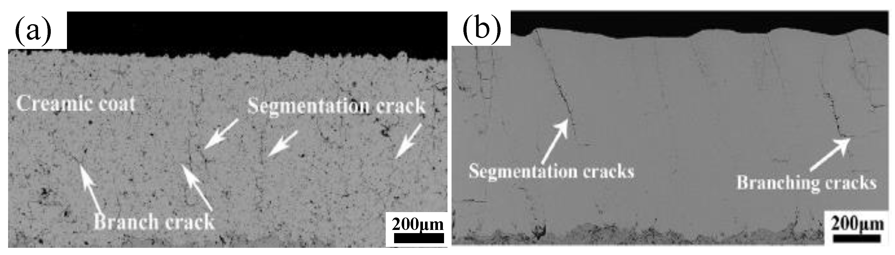
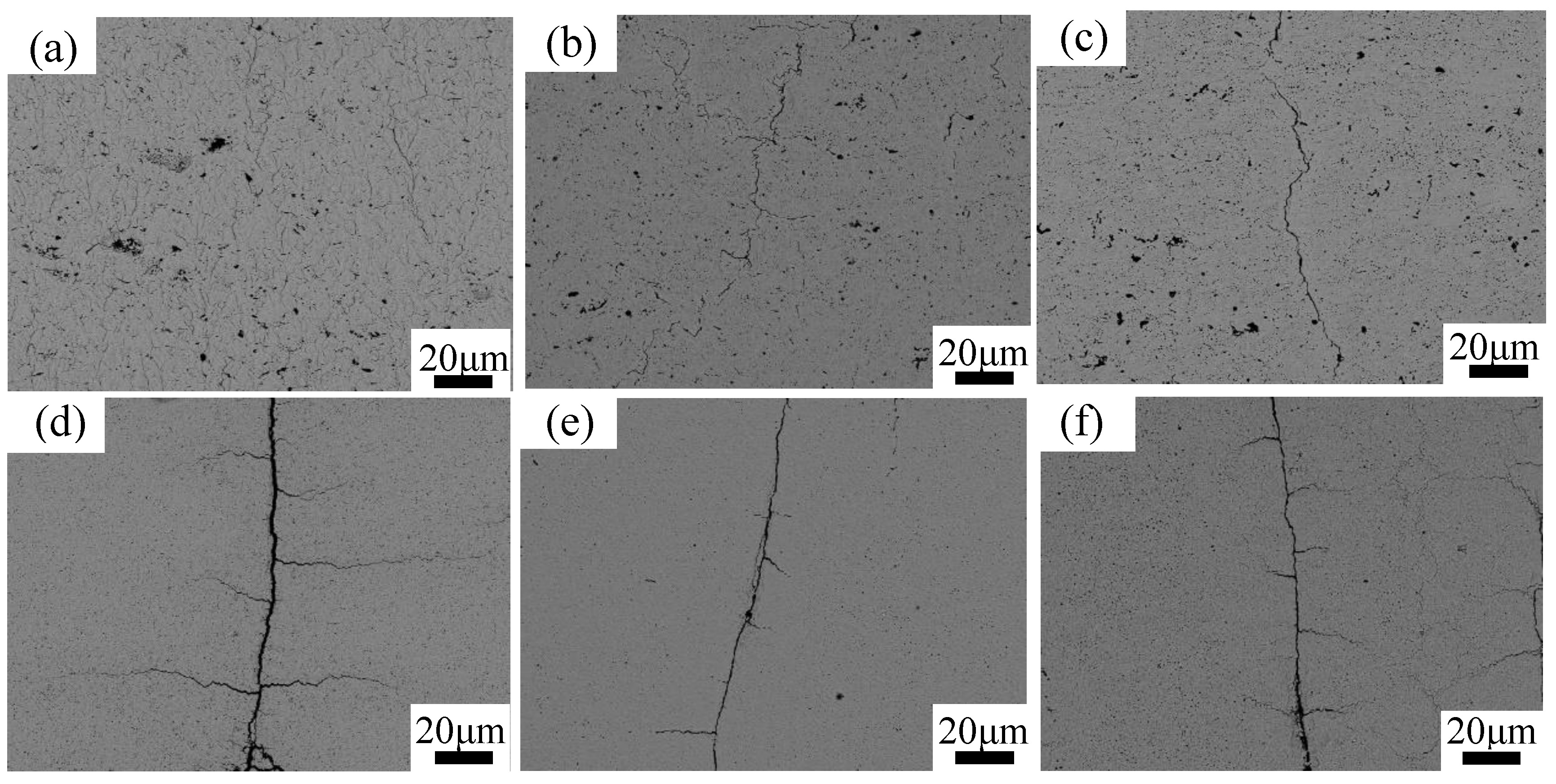
Both of the coatings displayed a unique microstructure with some obvious segmentation cracks and branching cracks. The measured Ds of the nanostructured APS and SPS YSZ coatings was about 2.5 cracks mm−1 and 4 cracks mm−1, respectively.
(2)
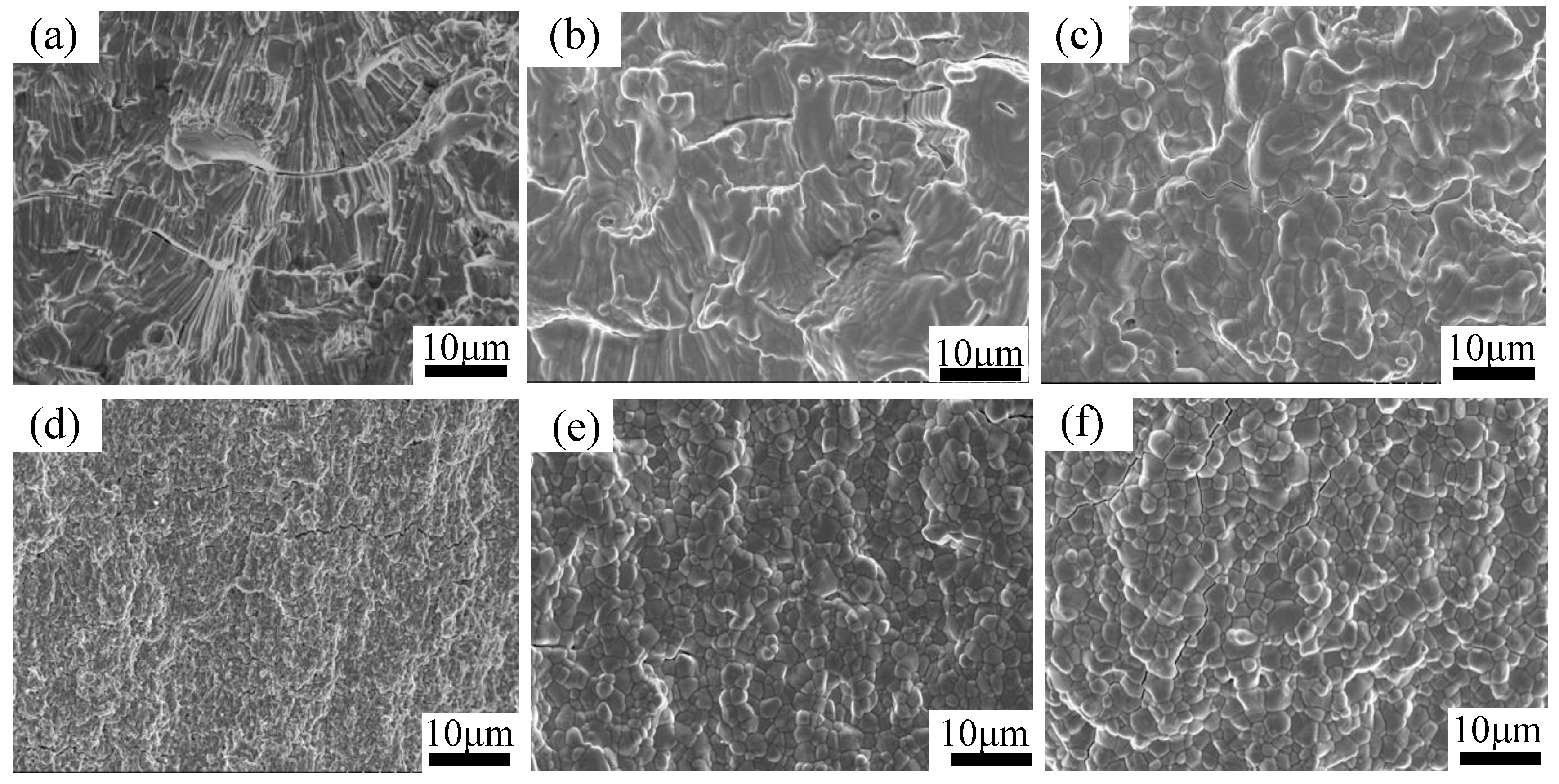
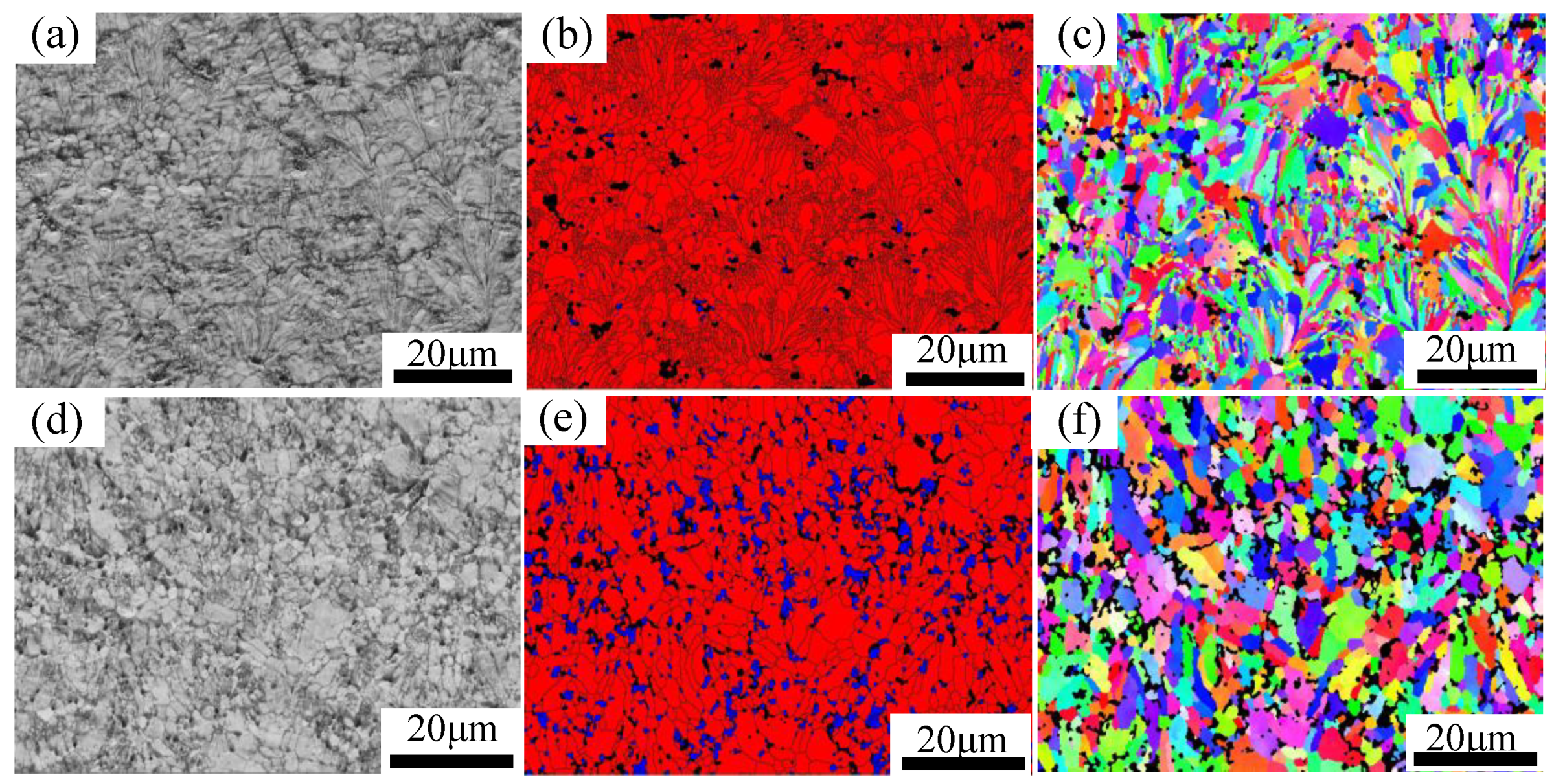
There were two distinct grain types in the two as-sprayed coatings: Larger columnar grains in the APS coating and smaller equiaxed grains in the SPS coating, revealing the different microstructure of the lamellar interface. The SPS coating was short of splats, while the splat-splat interactions in the APS coating were evident.
(3)
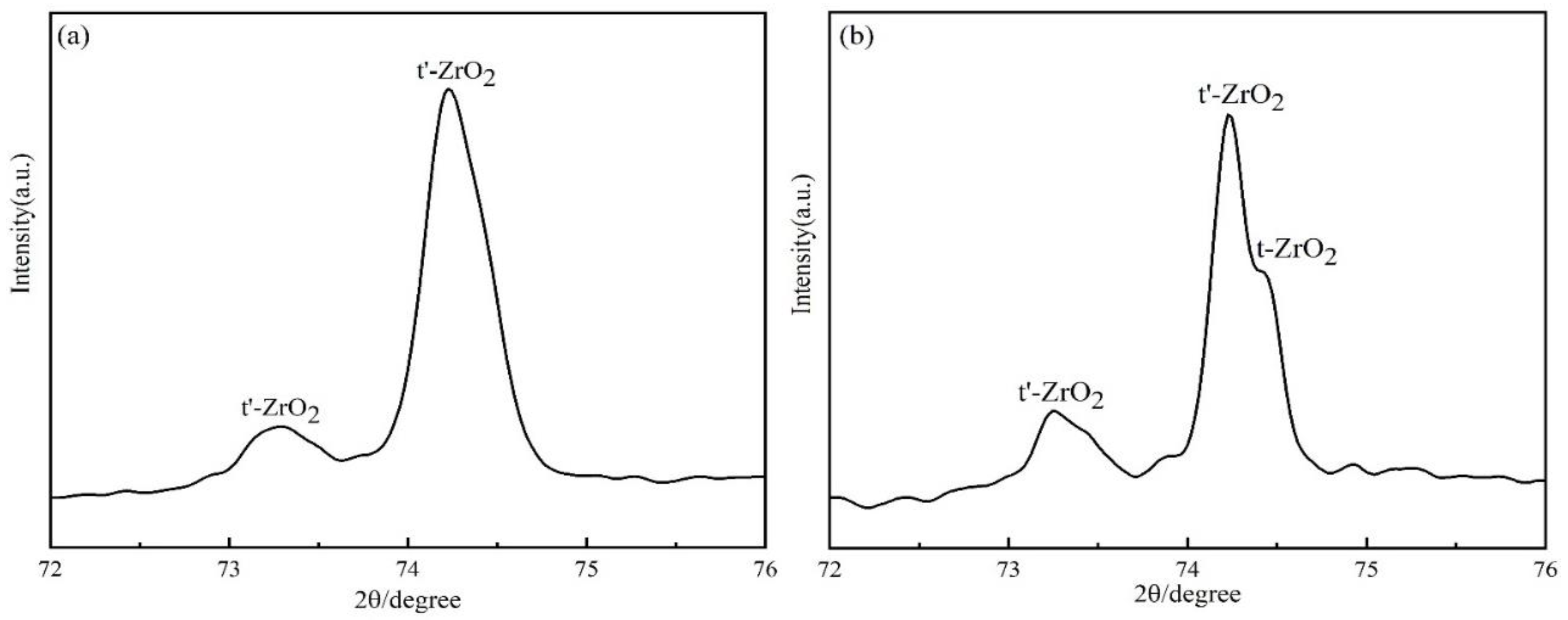
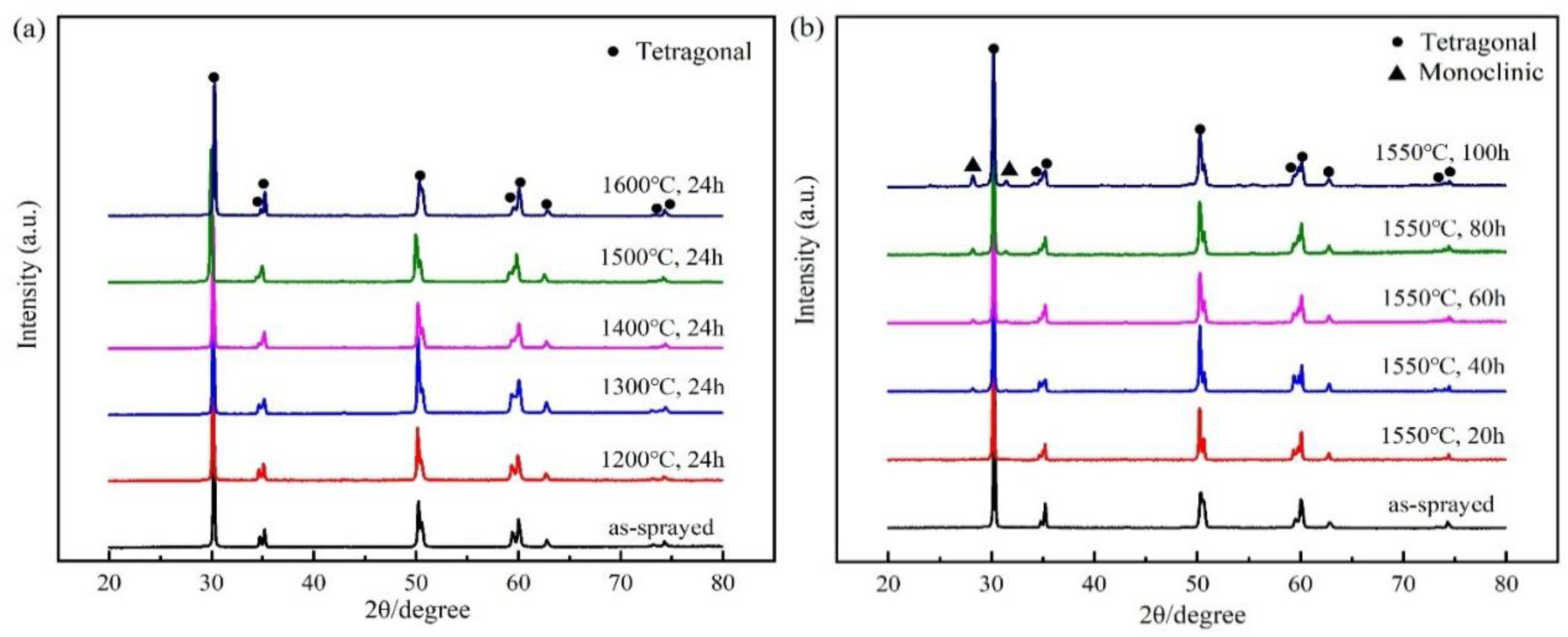
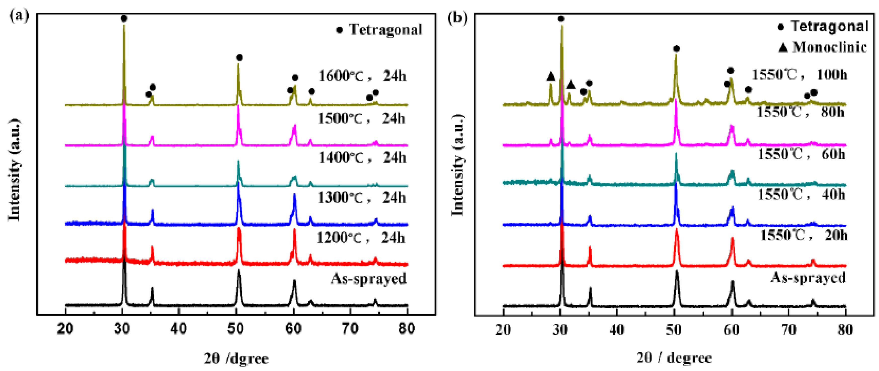
The initial metastable tetragonal (t’) phase of the APS and SPS coatings underwent tetragonal-monoclinic phase transformation after 1550 °C/40 h heat treatment. The poorer phase stability of SPS TTBCs may have a connection with the smaller grain size.
(4)
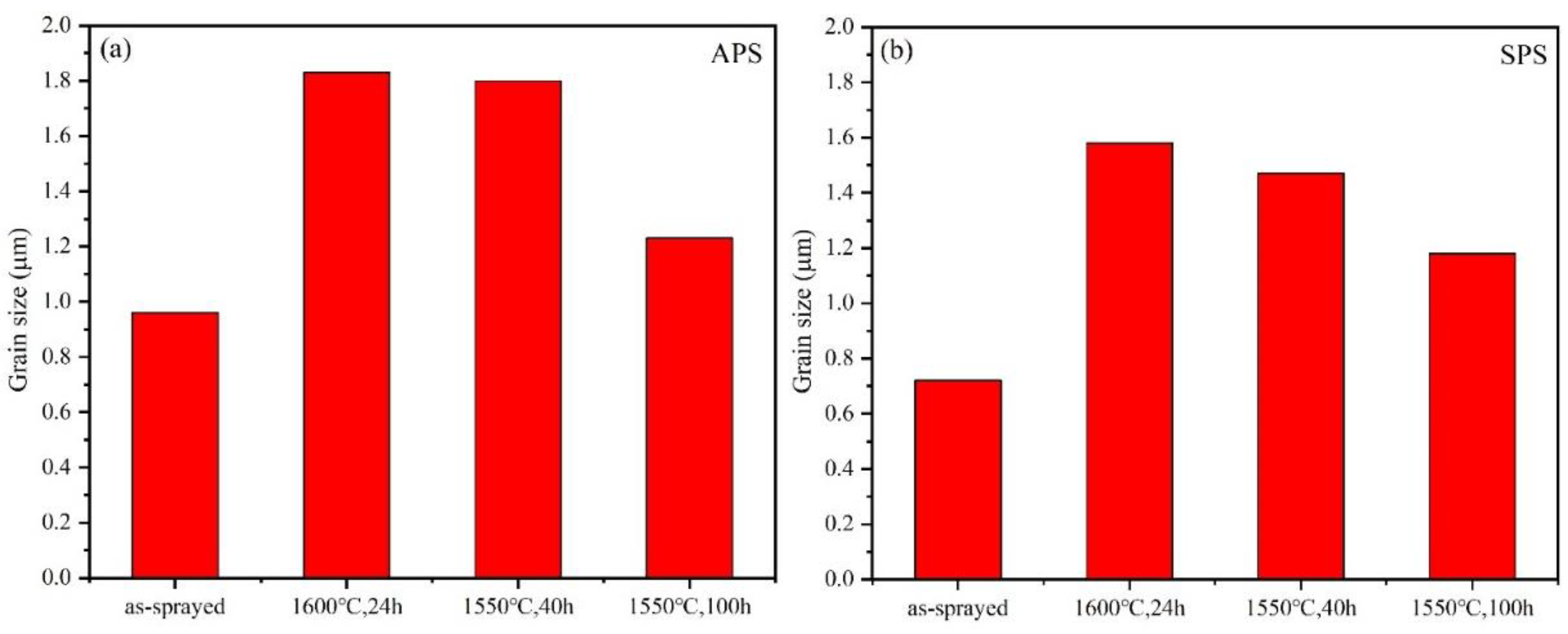
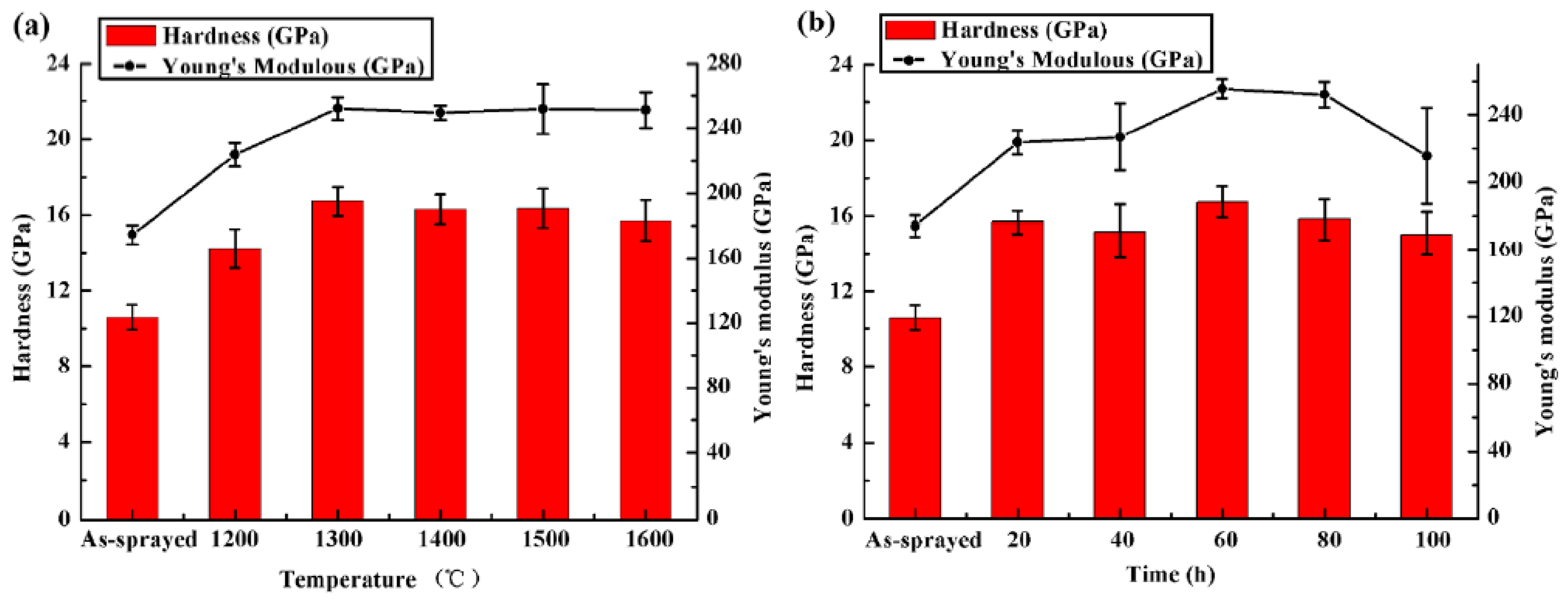
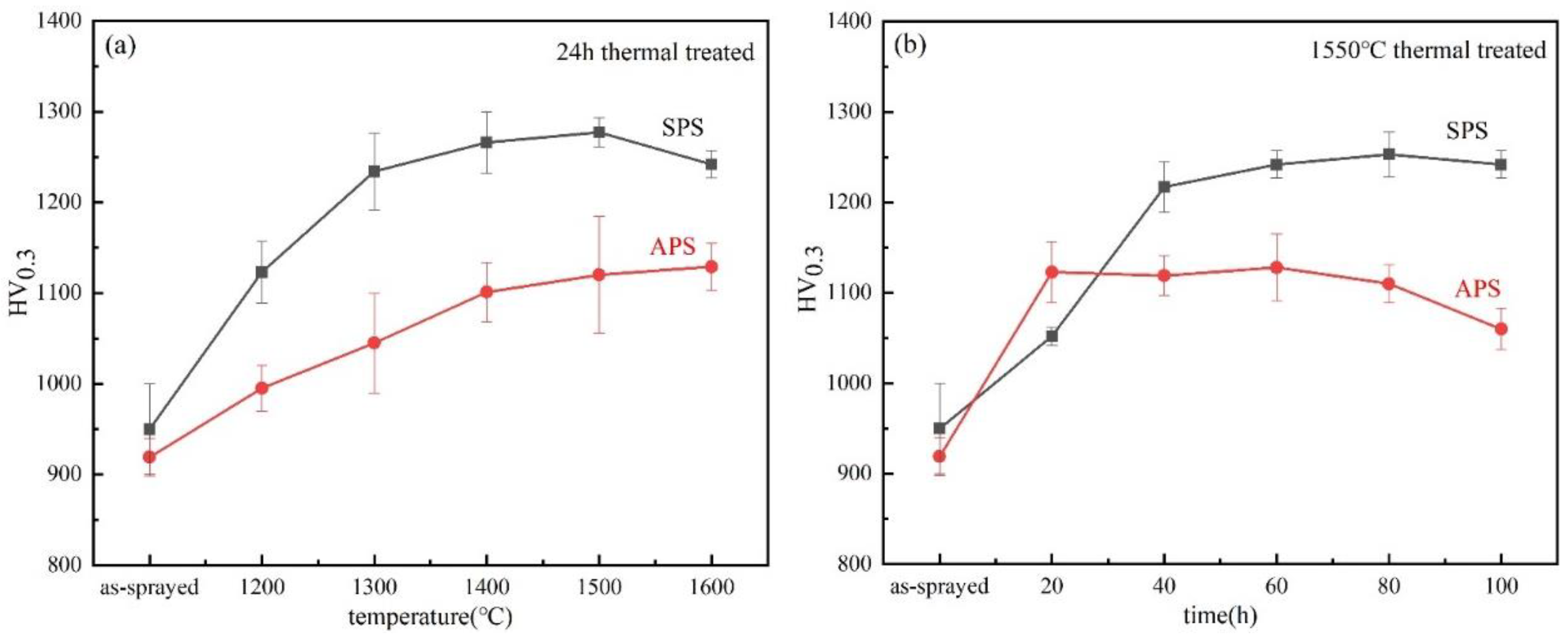
Thermal-aged APS and SPS coatings exhibited a significant increase in H and E values accompanied by pores healing and grain growth, and for the samples thermal aged at 1550 °C, the H and E values increased sharply during the initial stage then decreased after 80 h due to the phase decomposition. The segmented APS coatings had weak bonding between the lamellaes and more uniform pores distribution during thermal exposure, which caused the mean Vickers hardness value of APS TTBCs to be much lower than that of SPS TTBCs.

Author Contributions

Conceptualization, S.T. (Shiqian Tao) and S.T. (Shunyan Tao); data curation, S.T. (Shunyan Tao), M.Z., X.Z., W.L., F.S., H.Z., Y.Z., and J.N.; formal analysis, S.T. (Shiqian Tao) and J.Y.; writing-original draft preparation, S.T. (Shiqian Tao); writing-review and editing, J.Y. and S.T. (Shunyan Tao). All authors have read and agreed to the published version of the manuscript.

Funding

This research was funded by National Science and Technology Major Project (No. 2017-VI-0010-0082), National Natural Science Foundation of China (NSFC) (No. 51701235 and No. 51971148), and Science and Technology Innovation of Shanghai (No. 18511108702).

Acknowledgments

The authors are grateful for the technical assistance provided by Shiqian Tao.

Conflicts of Interest

The authors declare no conflict of interest.

References

  1. Parks, W.; Hoffman, E.; Lee, W. Thermal barrier coatings issues in advanced land-based gas turbines. J. Therm. Spray Technol. 1997, 6, 187–192. [Google Scholar] [CrossRef] [Green Version]
  2. Padture, N.; Gell, M.; Jordan, E. Materials science-Thermal barrier coatings for gas-turbine engine applications. Science 2002, 296, 280–284. [Google Scholar] [CrossRef] [PubMed]
  3. Gurrappa, I.; Sambasiva, R. Thermal barrier coatings for enhanced efficiency of gas turbine engines. Surf. Coat. Technol. 2006, 201, 3016–3029. [Google Scholar] [CrossRef]
  4. Liu, Y.; Hu, X. Segregation and microstructural evolution at interfaces of atmospheric plasma sprayed thermal barrier coatings during thermal cycling. J. Alloys Compd. 2020, 819. in press. [Google Scholar] [CrossRef]
  5. Vassen, R.; Stuke, A.; Stover, D. Recent developments in the field of thermal barrier coatings. J. Therm. Spray Technol. 2009, 18, 181–186. [Google Scholar] [CrossRef]
  6. Levi, C. Emerging materials and processes for thermal barrier systems. Curr. Opin. Solid State Mater. Sci. 2004, 8, 77–91. [Google Scholar] [CrossRef]
  7. Steffens, H.D.; Babiak, Z.; Gramlich, M. Some aspects of thick thermal barrier coating lifetime prolongation. J. Therm. Spray Technol. 1998, 8, 517–522. [Google Scholar] [CrossRef]
  8. Zhu, D.; Miller, R. Sintering and creep behavior of plasma-sprayed zirconia-and hafnia-based thermal barrier coatings. Surf. Coat. Technol. 1998, 108, 114–120. [Google Scholar] [CrossRef] [Green Version]
  9. Eaton, H.; Novak, R. Sintering studies of plasma-sprayed zirconia. Surf. Coat. Technol. 1987, 32, 227–236. [Google Scholar] [CrossRef]
  10. Bengtsson, P.; Ericsson, T.; Wigren, J. Thermal shock testing of burner cans coated with a thick thermal barrier coating. J. Therm. Spray Technol. 1998, 7, 340–348. [Google Scholar] [CrossRef]
  11. Guo, H.; Vassen, R.; Stover, D. Atmospheric plasma sprayed thick thermal barrier coatings with high segmentation crack density. Surf. Coat. Technol. 2004, 186, 353–363. [Google Scholar] [CrossRef]
  12. Karger, M.; Vassen, R.; Stover, D. Atmospheric plasma sprayed thermal barrier coatings with high segmentation crack densities: Spraying process, microstructure and thermal cycling behavior. Surf. Coat. Technol. 2011, 206, 16–23. [Google Scholar] [CrossRef]
  13. Guo, H.; Murakami, H.; Kuroda, S. Thermal cycling behavior of plasma sprayed segmented thermal barrier coatings. Mater. Trans. 2006, 47, 306–309. [Google Scholar] [CrossRef] [Green Version]
  14. Tao, S.; Yang, J.; Li, W. Thermal stability of plasma-sprayed thick thermal barrier coatings using Triplex ProTM-200 torch. Coatings 2020, 10, 894. [Google Scholar] [CrossRef]
  15. Zhai, M.; Li, D.; Zhao, Y. Comparative study on thermal shock behavior of thick thermal barrier coatings fabricated with nano-based YSZ suspension and agglomerated particles. Ceram. Int. 2016, 153, 12172–12179. [Google Scholar] [CrossRef]
  16. Guo, H.; Murakami, H.; Kuroda, S. Effects of heat treatment on microstructures and physical properties of segmented thermal barrier coatings. Mater. Trans. 2005, 46, 1775–1778. [Google Scholar] [CrossRef] [Green Version]
  17. Thompson, J.; Clyne, T. The effect of heat treatment on the stiffness of zirconia top coats in plasma-sprayed TBCs. Acta Mater. 2001, 49, 1565–1575. [Google Scholar] [CrossRef]
  18. Witz, G.; Shklover, V.; Steurer, W. Phase evolution in yttria-stabilized zirconia thermal barrier coatings studied by rietveld refinement of X-ray powder diffraction patterns. J. Am. Ceram. Soc. 2007, 90, 2935–2940. [Google Scholar] [CrossRef]
  19. Keyvani, A.; Saremi, M.; Sohi, M. An investigation on oxidation, hot corrosion and mechanical properties of plasma sprayed conventional and nanostructured YSZ coatings. Surf. Coat. Technol. 2011, 206, 208–216. [Google Scholar] [CrossRef]
  20. Cheng, Z.; Yang, J.; Shao, F. Thermal Stability of YSZ Coatings Deposited by Plasma Spray–Physical Vapor Deposition. Coatings 2019, 9, 464. [Google Scholar] [CrossRef] [Green Version]
  21. Chevalier, J.; Gremillard, L.; Virkar, A.V.; Clarke, D.R. The tetragonal-monoclinic transformation in zirconia: Lessons learned and future trends. J. Am. Ceram. Soc. 2009, 92, 1901–1920. [Google Scholar] [CrossRef]
  22. Ganvir, A.; Markocsan, N.; Joshi, S. Influence of isothermal heat treatment on porosity and crystallite size in axial suspension plasma sprayed thermal barrier coatings for gas turbine applications. Coatings 2017, 7, 4. [Google Scholar] [CrossRef] [Green Version]
  23. Zhao, Y.; Wang, L.; Yang, J. Thermal aging behavior of axial suspension plasma-sprayed yttria-stabilized zirconia (YSZ) thermal barrier coatings. J. Therm. Spray Technol. 2015, 24, 338–347. [Google Scholar] [CrossRef]
  24. Zhao, Y.; Li, D.; Zhong, X. Thermal shock behaviors of YSZ thick thermal barrier coatings fabricated by suspension and atmospheric plasma spraying. Surf. Coat. Technol. 2014, 249, 48–55. [Google Scholar] [CrossRef]
Figure 1. XRD patterns of as-sprayed coatings with 2θ between 72° and 76°: (a) APS coating; (b) SPS coating.
Crystals 10 00984 g001
Figure 2. XRD patterns of as-sprayed nanostructured APS coating and heated-treated APS coatings: (a) Samples after aging for 24 h at different temperatures; (b) samples after aging at 1550 °C for different times.
Crystals 10 00984 g002
Figure 3. XRD patterns of as-sprayed SPS coating and heated-treated SPS coatings [23]: (a) Samples after aging for 24 h at different temperatures; (b) samples after aging at 1550 °C for different times.
Crystals 10 00984 g003
Figure 4. Cross-sectional microstructures of as-sprayed TTBCs: (a) Nanostructured APS TTBCs [15], (b) SPS TTBCs [24].
Crystals 10 00984 g004
Figure 5. Fracture morphology of free-standing specimens: (ac) Nanostructured APS coating, (df) SPS coating; (a,d) as-sprayed, (b,e) 1600 °C/24 h, (c,f) 1550 °C/100 h.
Crystals 10 00984 g005
Figure 6. Polished cross-sectional morphology: (ac) Nanostructured APS coating, (df) SPS coating; (a,d) as-sprayed, (b,e) 1600 °C/24 h, (c,f) 1550 °C/100 h.
Crystals 10 00984 g006
Figure 7. EBSD images of nanostructured APS coatings before and after heat treatment: (a,d) Band contrast maps, (b,e) phase maps, (c,f) orientation maps; (ac) as-sprayed, (df) 1550 °C/100 h.
Crystals 10 00984 g007
Figure 8. EBSD images of SPS coatings before and after heat treatment: (a,d) Band contrast maps, (b,e) phase maps, (c,f) orientation maps; (ac) as-sprayed, (df) 1550 °C/100 h.
Crystals 10 00984 g008
Figure 9. Grain size of YSZ coatings before and after thermal treatment: (a) Nanostructured APS TBCs; (b) SPS TBCs.
Crystals 10 00984 g009
Figure 10. Hardness and Young’s modulus of the as-sprayed and heat-treated nanostructured APS coatings: (a) Samples after thermal aging treated at different temperatures for 24 h; (b) thermal aging treated at 1550 °C for different times.
Crystals 10 00984 g010
Figure 11. Hardness and Young’s modulus of the as-sprayed and heat-treated SPS coatings [23]: (a) Samples after thermal aging treated at different temperatures for 24 h; (b) thermal aging treated at 1550 °C for different times.
Crystals 10 00984 g011
Figure 12. Variation of Vickers hardness of nanostructured APS and SPS coatings with thermal aging treatment: (a) Samples after thermal aging treated at different temperatures for 24 h; (b) thermal aging treated at 1550 °C for different times.
Crystals 10 00984 g012
Table 1. The spraying parameters applied for the (yttria-stabilized zirconia) YSZ coating.
ParametersAPS CoatingSPS Coating
Plasma gas mixtureH2 + ArH2 + Ar + N2
Plasma gas flow rate (slpm)H2: 7–9H2: 20–25
Ar: 30–36Ar: 170–176
N2: 48–53
Carrier gas (slpm)Ar: 3.0–3.514.5–15.2
Powder inject diameter (mm)1.81.5
Stand-off distance (mm)80–8570–90
Feed rate (g/min)3040
Table 2. The microstructure parameters of coatings before and after thermal treatment.
SamplesTetragonal Phase (%)Monoclinic Phase (%)Average Grain Size (μm)
APS TTBCsas-sprayed95.50.410.96
1600 °C/24 h97.80.791.83
1550 °C/100 h82.69.381.23
SPS TTBCsas-sprayed99.40.010.72
1600 °C/24 h95.62.451.58
1550 °C/100 h70.421.11.18
Publisher’s Note: MDPI stays neutral with regard to jurisdictional claims in published maps and institutional affiliations.

