Article

Syntheses and Step-by-Step Morphological Analysis of Nano-Copper-Decorated Carbon Long Fibers for Aerospace Structural Applications

1
Department of Chemistry, College of Science, Imam Mohammad ibn Saud Islamic University (IMSIU), Al Riyadh 11623, Saudi Arabia
2
Department of Production Technology, Faculty of Technology and Education, Helwan University, Cairo 11281, Egypt
3
Department of Engineering and Construction, University of East London, London E16 2RD, UK
*
Author to whom correspondence should be addressed.
Crystals 2020, 10(12), 1090; https://doi.org/10.3390/cryst10121090
Submission received: 24 September 2020 / Revised: 9 November 2020 / Accepted: 26 November 2020 / Published: 28 November 2020

Abstract

:
Carbon long fiber/copper composites were prepared using electroless and electroplating methods with copper metal for potential aerospace applications. Carbon fibers were heat-treated at 450 °C followed by acid treatment before the metallization processes. Three different methods of metallization processes were applied: electroless silver deposition, electroless copper deposition and electroplating copper deposition. The metallized carbon fibers were subjected to copper deposition via two different routes. The first method was the electroless deposition technique in an alkaline tartrate bath using formaldehyde as a reducing agent of the copper ions from the copper sulphate solution. The second method was conducted by copper electroplating on the chemically treated carbon fibers. The produced carbon fiber/copper composites were extensively investigated by Field-Emission Scanning Electron Microscopy (FE-SEM) supported with an Energy Dispersive X-Ray Analysis (EDAX) unit to analyze the size, surface morphology, and chemical composition of the produced carbon long fiber/copper composites. The results show that the carbon fiber/copper composites prepared using the electroplating method had a coated type surface morphology with good adhesion between the copper coated layer and the surface of the carbon fibers. However, the carbon fiber/copper composites prepared using the electroless deposition had a decorated type morphology. Moreover, it was observed that the metallized carbon fibers using the silver method enhanced the electroless copper coating process with respect to the electroless copper coating process without silver metallization. The electrical conductivity of the carbon fiber/copper composites was improved by metallization of the carbon fibers using silver, as well as by the electrodeposition method.

1. Introduction

Advanced materials and carbon-fiber composites are used extensively throughout revolutionary aircrafts such as Boeing 787 Dreamliner and Airbus A350 family [1]. The stiffness, lightness, and toughness of the carbon fiber allowed technologists to create a very-low-drag delta wing body and fuselage. These advanced carbon fiber composites lead to not only lighter aircraft but also lower fatigue sensitivity, which means they require less maintenance. The Boeing 787’s heavy maintenance interval was increased from 6 to 13 years [1]. Carbon-fiber-reinforced plastics (CFRPs) constitutes more than 50 vol.% of these aerospace mobile structures, as represented in Figure 1. CFRPs are micro-composites formed from a lightweight polymer binder (e.g., epoxy) with laid carbon fiber to manufacture structures having extraordinarily high stiffness and strength-to-weight ratios.
This revolutionary technology (Figure 1) relies on the superlative combination properties of CFRPs primarily contributed by carbon fibers [2,3,4,5,6]. Carbon fibers, containing more than 92% by weight of carbon, have high strength, low density (1.8 g/cm3, light weight, high breaking strength (2–7 GP), high tensile modulus (200–500 GPa), and a low thermal expansion coefficient (0.1–1.1 × 10⁻⁶ K−1) [3,7]. They are also characterized by high resistance to acids, alkalis, and organic solvents. Carbon fibers have a low coefficient of thermal expansion and a good electrical conductivity, as well as low x-ray absorption and nonmagnetic properties [8,9,10]. The as-produced carbon fibers usually have relatively smooth surfaces, low surface energy, low chemical reactivity, and lack of chemically active functional groups, which have a significant effect on their mechanical properties and restrict their extensive applications [11,12].
Wing boxes, made of CFRP, are able to support the load imposed during flight and support the whole aircraft aerodynamically while also strategically minimizing their overall contribution to the weight of an aircraft. However, CFRPs, unlike like their aluminum counterparts, do not conduct electricity. This makes them susceptible to lightning strike damage and to mitigate such a drawback, an electrically conductive expanded copper foil layer is usually laid on the outer surface of the composite structure layup [13]. If a lightning bolt strikes an unprotected composite structure, up to 200,000 amps of electricity seeks the path of least resistance and may vaporize metal control cables and weld hinges on control surfaces or explode fuel vapors within fuel tanks if the current arcs through gaps around fasteners [1]. High electrical conductivity is, therefore, required here to dissipate the high current and heat generated by a lightning strike. However, expanded copper foil (ECF) layer possess issues of its own. Temperature and atmospheric pressure variations (for instance, 50 °C to −50 °C and 100 to 25 kPa, respectively) during the ground-to-air flight cycle can lead to the expansion and reduction of the protective layer, which can damage the relatively less resilient epoxy matrix of CFRPs, reducing the overall effectiveness of the composite substitution.
Here, we synthesized nano-copper-influenced carbon fibers as an alternate technology for the ECF laid on top of the CFRP wing box. Carbon fibers, generally speaking, have poor wetting behavior with metals such as copper and aluminum [12,14,15,16,17].
It is necessary to modify the surfaces of carbon fibers to resolve this key issue. One of the widely researched solutions is to coat the carbon fibers with metal layers. This method also reduces their susceptibility to interfering with the matrix and avoids the interaction of carbon fibers with several metals such as iron [18]. Metal-coated carbon fibers can also be used as a reinforcement phase in different metal matrix composites for different applications such as electric contact materials and electric brushes [16,19], as well as for the fabrication of fiber composites used automotive and aerospace sectors and other electrical equipment [20]. Materials with high electrical and thermal conductivities in combination with a low coefficient of thermal expansions are currently required for electrical and electronic applications. Carbon fiber/Cu composites possess the properties of copper, i.e., the excellent electrical and thermal conductivities, and the properties of carbon fiber, i.e., small coefficient of thermal expansion. These composites can be used in electrical and electronic applications. The electrical conductivity of carbon fiber/Cu composite materials is very important, particularly if these materials are used for electrical and electronic applications. The materials for this application should possess high electrical and thermal conductivities. Carbon fiber/Cu composites have successfully solved this problem. In this type of material, carbon is utilized because of its good sliding and antifriction properties, whilst copper is used because of its high electrical and thermal conductivities [16,19]. Various other studies have been conducted to improve the wetting of carbon fibers to metals. An SnCl2/PdCl2 solution is used as activating solution by depositing Pd nanoparticles on the surface of the carbon fibers before coating using the electroless deposition technique [21,22]. Electroless deposition can take place after the surface has been activated by Pd particles via the autocatalytic reaction to deposit metal nanoparticles on the surface of carbon fibers [23].
In another report, deposition of silver nanoparticles or films using electroless silver deposition was used for obtaining surface activity and improving their electrical conductivity and physical properties. Activation by silver aerosols and copper electrolyte deposition was also considered. After annealing, silver-activated carbon fibers were effectively placed in a solution for electroplating copper, to obtain a uniform copper coating on their surface [
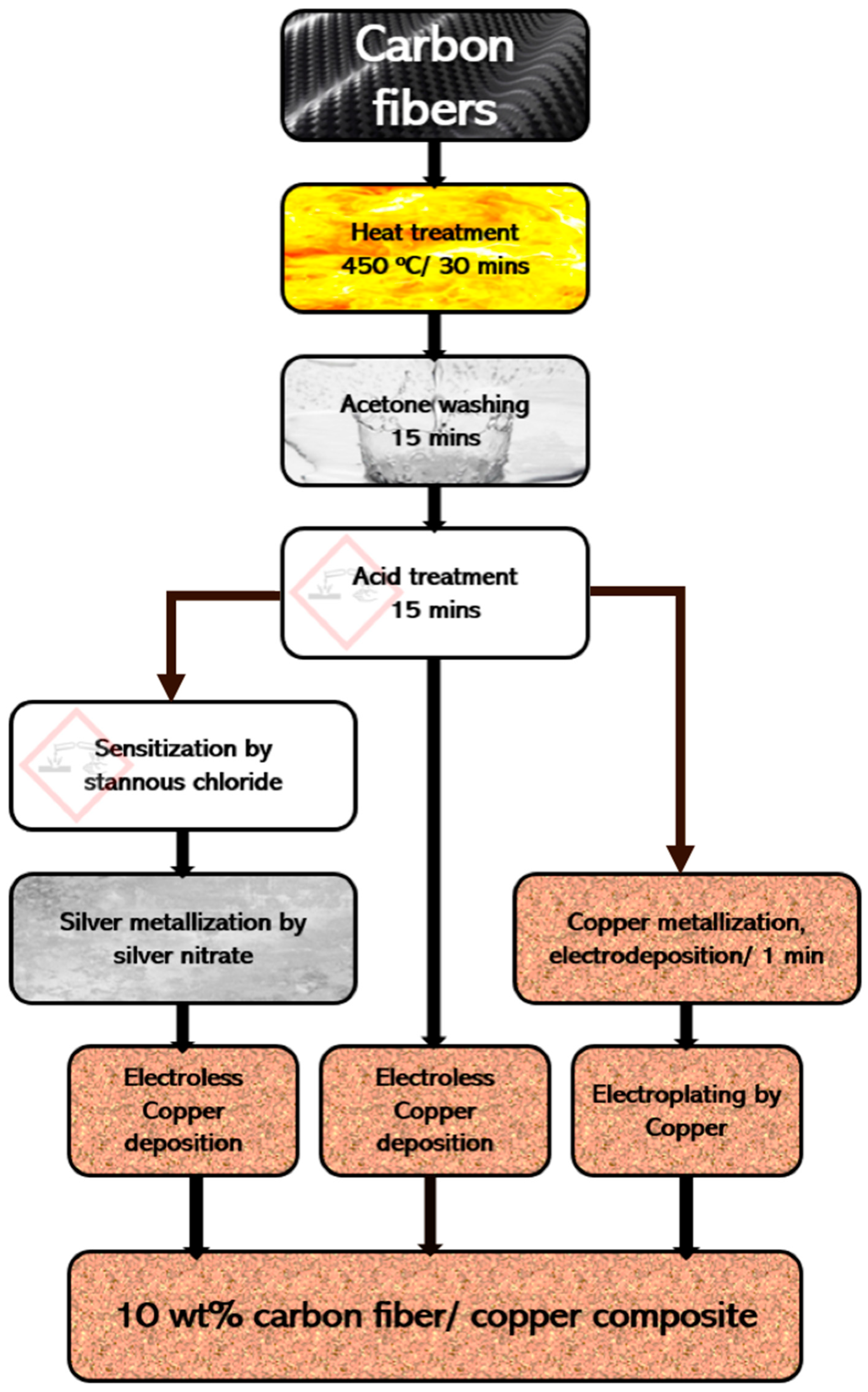
24]. Electroplating Cu was utilized to increase the thickness of the interlayer and forming a coating layer with a good adhesion with the surfaces of the carbon fibers. The current work utilizes a superlative combination of properties offered by carbon fiber (PAN: Polyacrylonitrile type) with high electrical conductivities of copper to synthesize a nano-copper-decorated carbon fiber nanocomposite via the coating route. To make these composites suitable for powder technology processing, surface treatment of the carbon fibers was essential via thermal de-binding, acid treatments, and/or a tin/silver metallization process before encapsulating the carbon fibers into the copper matrix using two coating methods, (electroless or electrodeposition) to produce a continuous conductive coating with uniform thickness. The contact electrical resistivity of the produced carbon fiber/Cu nanocomposites using either electroless or electrodeposition techniques was measured as well.

2. Materials and Methods

2.1. Starting Materials

High-purity PAN-type long carbon fibers were provided by Mitsubishi Chemical Carbon Fiber and Composites Ltd. (Sacramento, USA). Each bundle was composed of around 1000 fibers, which were bonded together with an organic binder (sizing agent). Table 1 lists the physical and mechanical properties of the carbon fibers used in this study. Copper sulfate pentahydrate was purchased from Winlab Ltd., Leicester, UK. Silver nitrate and stannous chloride dihydrate were purchased from BDH Chemicals Ltd., East Yorkshire, UK. Potassium sodium tartrate and potassium dichromate were provided by Merck Ltd., Darmstadt, Germany. Formaldehyde and sodium hydroxide were purchased from Panreac AppliChem, Barcelona, Spain. Acetone, hydrochloric acid, ammonia solution, nitric acid, and sulfuric acid were provided by Riedel De-Haen, Seelze, Germany.

2.2. Methods

2.2.1. Pretreatment of Carbon Fibers

Carbon fibers were treated as described in Figure 2. In brief, the bundles of as-received carbon long fibers were cut into strands of around 6 cm in length and then heat-treated at 450 °C for 30 min in an open oven (Figure 3) to remove any sizing, binding, and degreasing agents. They were then washed in acetone for 15 min followed by washing with distilled water to remove any organic remained contaminants. The obtained carbon long fibers were then acid-treated by concentrated nitric acid, and then stirred in a freshly prepared chromic acid solution for 15 min (by dissolving 5 g of potassium dichromate in 5 mL distilled water in the form of a paste, before adding 100 mL of 98% concentrated sulfuric acid dropwise). This was then followed by washing thoroughly (at least three times in deionized water) to remove any inorganic impurities on the surface of the carbon fibers. The obtained carbon fibers were dried for 15 min at 110 °C.

2.2.2. Metallization of Carbon Fibers Using the Tin/Silver Process

As elaborated in Figure 2, a batch of heat-treated and etched carbon fibers were further activated. The activation process included two steps: sensitization and silver deposition. About 0.01 g of the treated carbon long fibers were treated using tin sensitization solution. The sensitizing agent was prepared by dissolving 0.1 g of SnCl2·2H2O in 10 mL of distilled water, and the pH of the solution was adjusted to around 1.8 using hydrochloric acid. The solution was stirred using a magnetic stirrer for 30 min. The sensitized carbon fibers were then washed with distilled water to remove any residuals of the sensitizing agent. The obtained sensitized carbon fibers were surface-activated using the silver deposition method. About 0.2 g of silver nitrate was dissolved in 100 mL of distilled water, and the pH of the solution was adjusted by ammonia to around 10.7. The sensitized carbon fibers were then added and the solution was stirred using magnetic stirring for 15 min. Then, 20 mL of formaldehyde was added to the solution. The reduction reaction was completed within 15 min, and then the activated carbon fibers were washed with distilled water, filtered, and dried at 110 °C for 30 min.

2.2.3. Metallization of Carbon Fibers Using the Copper Deposition Processes

Two processes were used to metallize the chemically treated carbon fibers with copper (Figure 2). The first method (electroless copper deposition) was conducted on the acid-treated carbon fibers in an alkaline tartrate bath. The solutions included in the process were 70 g/L copper sulfate as a source of copper, 170 g/L potassium sodium tartrate as a chelating agent of the copper ions, and 100 mL/L formaldehyde as a reducing agent of the copper ions to copper in the metallic state. The pH of the solution was adjusted to around 13, and the temperature was maintained at room temperature (~24 °C). After completion of the copper deposition reaction, the metallized carbon fibers underwent washing with distilled water, filtration, and drying at 110 °C for 30 min.
The second metallization process was the electrodeposition of copper nanoparticles on the surface of the chemically treated carbon fibers. The acid-treated carbon long fibers (around 6 cm in length) were stretched on a cathode frame made from plastic. The current and time were adjusted to get the required copper deposition on the carbon long fibers. In brief, 120 g of copper sulfate pentahydrate and 90 mL of sulfuric acid were dissolved in distilled water (via 30 min of magnetic stirring) to prepare 1 L of electrolyte solution. The copper electrodeposition on the surface of the carbon long fibers was achieved by passing 8 µA current for 1 min.

2.2.4. Syntheses of Carbon Fiber/Copper Composites

The acid-treated and tin/silver-metallized carbon fibers were coated using an electroless copper chemical reduction method to prepare 10 wt.% carbon fiber/copper composite samples (Figure 2). About 0.35 g of copper sulfate pentahydrate was dissolved in 10 mL of distilled water, and the solution was stirred using a magnetic stirrer. About 1.7 g of potassium sodium tartrate was added as chelating agent to prevent precipitation of copper as copper hydroxide at high pH of the alkaline solution. Then, 0.5 g of sodium hydroxide was added to adjust the pH to 12.5. A calculated amount of ~0.01 g equivalent to 10 wt.% carbon long fibers was added to the solution, and continuous magnetic stirring at 500 rpm was used to disperse the fibers in the solution. Then, 10 mL of formaldehyde solution (38%) was added as a reducing agent of the copper ion in the copper sulfate to copper metal. The reaction on the surface of the treated carbon fiber was completed within 30 min. The solution was filtered, and the obtained 10 wt.% carbon fiber/copper composite was dried at 110 °C.
On the other hand, the metallized carbon long fibers using copper electroplating were connected to the negative electrode of the electroplating cell of the same composition as mentioned in Section 2.2.3, where two copper plates were connected to the positive electrode. Direct current of density 12 µA/cm2 was passed through the electroplating cell at time intervals of 5 min.

2.2.5. Characterization of Carbon Fiber/Copper Composites

The as-received, heat-treated, and chemically treated carbon fibers and the activated, metallized, and copper-coated carbon fibers underwent investigations using a field-emission scanning electron microscope (FE-SEM, model JEOL JSM-7600F). The powders were sputter coated by a platinum JFC 1600 auto fine coater. The compositional analysis of the samples was determined using the Energy Dispersive X-Ray Analysis (EDAX) unit connected with the FE-SEM.
The electrical resistivity of the prepared carbon fiber/Cu nanocomposites was measured using the four-probe method with an Omega multimeter device. A fixed direct current (DC) current of 1 A was passed through the test sample via two crocodile clips. For each test, the multimeter was zeroed with no current passing the specimen, and then the measurement was carried out. The resistivity (ρ) was calculated according to the following equation:
R = (ρ L)/A,
where R is the resistance in Ω, L is the measured length in cm, A is the cross-section area in cm2, and ρ is the resistivity in µΩ·cm. The dimensions of the fibers were calculated according to the data listed in Table 1. Each bundle was composed of around 1000 fibers of diameter ~7 μm and length ~6 cm.

3. Results and Discussion

Figure 4 shows the SEM images of as-received carbon fibers. It was observed that the fibers had diameters of approximately 6.7 µm, as roughly confirmed in Table 1.
Carbon long fibers were heat-treated to remove some of the volatile organic materials such as the sizing agents which were added to the fibers during the fabrication process. Figure 5 shows the SEM images with different magnifications and the EDAX compositional analysis of the carbon fibers after heat treatment. Comparing the surface morphology of the untreated carbon fibers (Figure 4) with the surface morphology of the heat-treated carbon fibers (Figure 5), it was observed that the layers of the sizing agent were partially removed as the carbon fiber surface in evident. Some other impurities composed of Ba, K, Cr, and oxygen were detected through the EDAX analysis of heat-treated carbon fibers due to the presence of remnants from the sizing agent. Figure 6 shows SEM images with different magnifications of the treated carbon fibers after washing and treating them with chromic acid. The results reveal that the diameter of the carbon fibers decreased from around 6.7 µm to around 5.1 µm due to heat and chemical treatments. The decrease in the diameter was due to the removal of the binding, sizing, and degreasing agents which adhered to the surface of carbon fibers as a consequence of heat and chemical treatments of the carbon fibers with acetone and chromic acid. A uniform morphological roughening of the carbon fiber was observed (Figure 6). This process was conducted to increase the bond strength of the applied deposits by increasing the surface roughness of the carbon fiber substrate. However, a very rough surface such as that of etched fibers is not recommended since it affects the smoothness and uniformity of the final deposits. Suitably rough surfaces create a network profile to which the subsequent deposit can be physically anchored and produce a uniform coating thickness.
The chemically treated carbon fibers were metallized using three different techniques, namely, electroless tin/silver deposition, electroless copper deposition, and copper electrodeposition.

3.1. Metallization of Carbon Fibers Using Electroless Tin/Silver Deposition

Some of the surface-etched carbon fibers were further sensitized and activated to impart a uniform conducting film on the fiber surfaces, ensuring uniform adhesion of subsequent metallization and further promoting better coating and plating.
Tin/silver sensitization and activation were carried out to deposit nanosized silver particles onto carbon fibers prior to the electroless copper coating operations. Tin(II) ions were adsorbed onto the carbon fiber surfaces and silver(I) ions were reduced to metallic silver nanoparticles. Silver nanoparticles were deposited onto the surface of the carbon fibers in the second step as shown in the chemical reaction below.
Sn++ (aq) + 2 Ag+ (aq) → Sn4+ (aq) + 2Ag0 (s)
Tin(IV) ions were produced from the oxidation of tin(II) ions by silver(I) ions. Figure 7a,b show the SEM image of the silver-activated carbon fibers. Deposited silver nanoparticles in the range of around 40–130 nm could be observed. These deposited silver nanoparticles decorated and adhered to the surface of the carbon fibers. Figure 7c,d show the EDAX compositional area analysis of the silver-activated carbon fibers. It was observed from the results that silver particles were composed mainly of 2.04 wt.% Ag and 0.61 wt.% tin, as remnants from the sensitization process.

3.2. Metallization of Carbon Fibers Using Electroless Copper Deposition

The chromic-acid-treated carbon fibers were subjected to autocatalytic electroless copper deposition on its surface in the alkaline tartrate copper sulfate solution. Figure 8a,b show the SEM images with different magnifications of the deposited copper nanoparticles on the acid-treated carbon fibers. It was observed from the results that the deposited copper nanoparticles had particle size range between 85 and 165 nm. The copper nanoparticles had polygonal particle shapes, and some agglomerated particles were also observed. The deposited copper nanoparticles adhered to the surface of the carbon fibers, imparting a decorative type copper layer. A good uniform deposition can be observed. Figure 7c,d show the EDAX compositional analysis of the metallized carbon fiber by the deposited copper nanoparticles. It was revealed that the copper nanoparticles were composed mainly of copper metal. The appearance of the small oxygen peak may be due to the oxidation of the surface of some deposited copper nanoparticles which were present in the aqueous solution during the process or due to the technical limitations of the EDAX technology with respect to the detection of oxygen.
The alkaline tartrate electroless copper solution used formaldehyde as a reducing agent of the copper ions to the copper metal. The half-cell reaction for the electroless copper deposition is shown below.
Cu++ + 2e → Cu0 E0 = +0.340 V
The rate of copper deposition was affected by the variation of the pH of the solution. Electroless copper solutions, using formaldehyde as a reducing agent, employed a high pH above 12. It was reported that the E0 of formaldehyde depends on the pH of the solution [22], as shown below.
HCOOH + 2H+ + 2e → HCHO + H2O (pH = 0, E0 = +0.05 V)
HOO + 2H2 + 2e → HCHO + 3OH (pH = 14, E0 = −1.07 V)
As copper salts (copper sulfate pentahydrate) are insoluble at pH above 4, the use of alkaline media necessitates the use of a complexing or chelating component, such as tartrate salts and ethylenediaminetetraacetic acid (EDTA) [22]. The full electroless copper deposition process at pH ~12 can be written according to the redox reaction below.
Cu2+ + 2HCHO + 4OH → Cu0 + H2 + 2H2O + 2HCO2

3.3. Metallization of Carbon Fibers Using Copper Electrodeposition

Electrodeposition is a common way of depositing of metals and its alloys on the surface of conductive materials. Copper is used in the electroplating process with either cyanide or sulfate baths. However, cyanide solutions are hazardous and should be avoided for industrial practices. An alternative approach is to use other acid baths to precipitate Cu. Chloride, oxalate, nitrate, thiosulfate, glycolate, lactate, and acetate have been reported; however, sulfate baths are the most commonly used [23].
A conventional acid electrochemical copper cell was used to electroplate carbon long fibers. This electrochemical cell consisted of copper sulfate and a sulfuric acid solution as the electrolyte. Two high-purity copper plates were used as anodes. A cathode of carbon fibers was inserted between the anodes in the solution. Copper ions of the copper sulfate were dissolved in the electroplating solution. The remaining SO42− anion played no part in the reactions and, therefore, does not appear in the equations [23]. The complete chemical reaction of the electroplating process of the carbon fibers confirmed the transfer of copper ions from the anode to the cathode passing through the electrolyte and depositing copper on the conductive carbon long fibers fixated on the cathode. It was assumed that the total copper ion concentration in the electrolyte remained unchanged.
Figure 9 shows SEM images with different magnifications of the deposited copper nanoparticles on the surface of the carbon long fibers upon passing a current of 8 µA for 1 min through the electrodeposition cell. It was observed that polygonal copper nanoparticles ranging between 85 and 135 nm in size were homogeneously deposited on the surface of the treated carbon fibers, giving a decorative morphology texture (Figure 9b).

3.4. Syntheses of Carbon Fiber/Copper Composites

The acid-treated, tin/silver-metallized, and copper-metallized carbon fibers were used to fabricate the 10 wt.% carbon fiber/copper composite via electroless coating and copper electroplating.
Figure 10a,b show SEM images with different magnifications of 10 wt.% carbon fibers coated via electroless deposition of copper on silver-metallized carbon fibers. The surface of the fibers was completely covered with multilayers composed of polygonal copper nanoparticles ranging in size from 50–100 nm. Figure 10c,d show the EDAX semiquantitative analysis of the produced 10 wt.% carbon long fiber/copper composite via electroless deposition in the alkaline potassium sodium tartrate bath using formaldehyde as a reducing agent. A compositional analysis of the copper-coated silver-metallized carbon fibers showed mainly copper and carbon. In addition, some silver and tin remained in the copper-coated layers from the earlier tin/silver metallization process.
Figure 11 shows SEM images with different magnifications for carbon fiber/copper composites prepared via the electroplating method. The morphology (Figure 11) was achieved using 12 µA/cm2 current density for 5 min. Carbon fibers were completely coated and covered by a dense copper layer. Fine copper particles were deposited on the surface of the carbon fibers. These particles appeared to be growing laterally, simultaneously forming a network and eventually becoming a layer of bulky copper clusters of particles. It was also noticed that the Cu deposits on the carbon fibers adhered very well to the carbon fibers, and the degree of tightness was higher than the Cu-coated carbon fibers fabricated via the electroless deposition method due to the absence of pores in the deposited layers. However, Figure 12 shows that there were some regions where there was no coating. Such regions could create some interfacial regions for the application discussed in this work. The EDAX compositional analysis of the prepared carbon fiber/copper composites via the electrodeposition method with 12 µA/cm2 current density is also shown in Figure 12. It was observed that the electrodeposited layer was composed mainly of copper on the surface of the carbon fibers.

3.5. Electrical Resistivity of Carbon Fiber/Copper Composites

The contact electrical resistivity for the fiber/deposit interface following electroless and electrolytic deposition for each Cu deposit condition was measured. The correlation provided qualitative analysis on the bonding and adhesion of the deposit to the carbon fibers. For example, a higher void content at the interface would result higher contact resistivity and lower adhesion. When measuring the contact electrical resistivity of the carbon fiber/deposit interfaces of the investigated Cu-coated fibers, as shown in Figure 13, it was found that the contact electrical resistivity of the carbon fiber/copper composites fabricated via electrodeposition was lower than that of the carbon fiber/copper composites fabricated via silver metallization and that of the non-metallized carbon fiber/copper composites fabricated via electroless deposition. This was probably due to the high purity of the deposited copper when using the electrodeposition method than the electroless one, as shown from Figure 10d and Figure 12b,d. Copper and carbon fibers have no mutual wettability and solubility. Accordingly, carbon fiber is mechanically bonded to copper matrix solely due to the fiber’s roughness. Thus, the interfacial adhesion between carbon fibers and the copper matrix remains weak. When carbon fibers are oxidized with CrO3, greater surface roughness is produced, resulting in better adhesion properties between the carbon fibers and Cu and leading to improved electrical conductivity. When the oxidized carbon is surface-activated and metallized with Sn/Ag solution, Ag acts as the active center for Cu deposition, consequently improving the carbon fiber/copper matrix interface and decreasing the percentage porosity, thereby resulting in a higher electrical conductivity. In addition, the resistivity of all the produced carbon fibers/copper composites was lower than that of the uncoated fibers (Figure 13). This means that the conductivity of carbon fibers was improved by the contribution of copper in the composite. Since copper is a face-centered cubic (FCC) crystalline material, it theoretically contributes a free electron per atom to the conduction bond where it is available for conducting electrical current. At any time, a certain number of free electrons can be at any given distance outside of the copper surface. Carbon fibers, similar to copper, also possess free electrons, which are available for conduction. In the case of two clean surfaces (i.e., carbon fiber and copper) placed together closely in an intimate contact, the free electrons are able to exchange positions without interference [25].

4. Conclusions

The present work provided an economical strategy highlighting the step-by-step synthesis and morphological analysis of nano-copper-decorated carbon fibers for aerospace structural applications. Carbon long fibers (PAN type) were successfully coated with copper using electroless or electrodeposition methods. The loading of copper coating was about 90 vol.%. Electroless silver deposition, electroless copper deposition, and copper electroplating were used to produce and analyze the conductive area coatings. The 10 wt.% carbon fiber/copper nanocomposites were subjected to heat and acid treatments followed by stannous chloride sensitization and the silver deposition method and/or electroless copper deposition and copper electroplating method, thereby producing continuous and selective area coatings of copper. The coating protocol was optimized to achieve a high degree of coating uniformity and conductivity as all samples were characterized for use in different conditions. Silver and copper nanoparticles ranging in size from 40–170 nm were deposited/decorated and adhered to the surfaces of treated carbon fibers. The morphology and thickness of conductive clusters of copper could be manipulated by varying the electrochemical variables as demonstrated in this study. It was concluded from the measurement of the electrical conductivity that the adhesion of the electrodeposited Cu coating on carbon fibers was the highest, followed by silver-metallized/electroless copper-coated carbon fibers and, lastly, electroless copper-coated carbon fibers. Such an optimization of variables could alter the performance of lightning protection measures for the outer layers of aerospace structures (e.g., wing box), which will be the subject of future research.

Author Contributions

Conceptualization, W.M.D. and F.I.; methodology, W.M.D., T.S.A. and M.A.K.; validation, W.M.D., T.S.A. and F.I.; formal analysis, W.M.D., T.S.A. and M.A.K.; investigation, W.M.D., T.S.A., M.A.K. and F.I.; resources, W.M.D., T.S.A., M.A.K. and F.I.; data curation, W.M.D., T.S.A. and M.A.K.; writing—original draft preparation, W.M.D., T.S.A., M.A.K. and F.I.; writing—review and editing, W.M.D. and F.I.; visualization, T.S.A., M.A.K. and W.M.D.; supervision, W.M.D. and F.I.; project administration, W.M.D. and F.I. All authors have read and agreed to the published version of the manuscript.

Funding

This research received no external funding.

Acknowledgments

The authors acknowledge all technicians of the SEM unit at the King Saud University for their cooperation and help during the investigations of our samples. Also, the authors would like to thank Nasr M. Khattab at Central Metallurgical R&D Institute for his guidance during the work.

Conflicts of Interest

The authors declare no conflict of interest.

References

  1. Mathijsen, D. What does the future hold for composites in transportation markets? Reinf. Plast. 2017, 61, 41–46. [Google Scholar] [CrossRef]
  2. Hegde, S.; Shenoy, B.; Chethan, K. Review on carbon fiber reinforced polymer (CFRP) and their mechanical performance. Mater. Today Proc. 2019, 19, 658–662. [Google Scholar] [CrossRef]
  3. Hiken, A. The Evolution of the Composite Fuselage: A Manufacturing Perspective, Aerospace Engineering, George Dekoulis, IntechOpen. 2018. Available online: https://www.intechopen.com/books/aerospace-engineering/the-evolution-of-the-composite-fuselage-a-manufacturing-perspective (accessed on 2 August 2020).
  4. Gupta, G.; Kumar, A.; Tyagi, R.; Kumar, S. Application and future of composite materials: A review. Int. J. Innov. Res. Sci. Technol. 2016, 5, 6907–6911. [Google Scholar]
  5. Hughes, H. The carbon–fiber epoxy interface—A review. Compos. Sci. Technol. 1991, 41, 13–45. [Google Scholar] [CrossRef]
  6. Naito, K.; Yang, M.; Kagawa, Y. Tensile properties of high strength polyacrylonitrile (PAN)-based and high modulus pitch-based hybrid carbon fibers–reinforced epoxy matrix composite. J. Mater. Sci. 2012, 47, 2743–2751. [Google Scholar] [CrossRef]
  7. Shirvanimoghaddam, K.; Hamim, S.; Akbari, K.; Fakhrhoseini, S.M.; Khayyam, H.; Pakseresht, A.H.; Ghasali, E.; Zabet, M.; Munir, K.S.; Jia, S.; et al. Carbon fiber reinforced metal matrix composites: Fabrication processes and properties. Compos. Part A 2017, 92, 70–96. [Google Scholar] [CrossRef]
  8. Inam, F.; Doris, W.; Wong, Y.; Kuwata, M.; Peijs, T. Multiscale Hybrid Micro-Nanocomposites Based on Carbon Nanotubes and Carbon Fibers. J. Nanomater. 2010, 2010, 453420. [Google Scholar] [CrossRef] [Green Version]
  9. Barton, B.; Behr, M.; Patton, J.; Hukkanen, E.J.; Landes, B.G.; Wang, W.; Horstman, N.; Rix, J.E.; Keane, D.; Weigand, S.; et al. High–modulus low–cost carbon fibers from polyethylene enabled by boron catalyzed graphitization. Small 2017, 13, 1701926–1701932. [Google Scholar] [CrossRef]
  10. Jabbour, L.; Chaussy, D.; Eyraud, B.; Beneventi, D. Highly conductive graphite/ carbon fiber/cellulose composite papers. J. Compos. Sci. Technol. 2012, 72, 616–623. [Google Scholar] [CrossRef]
  11. Calderon, N.; Voytovych, R.; Narciso, J.; Eustathopoulos, N. Wetting dynamics versus interfacial reactivity of AlSi alloys on carbon. J. Mater. Sci. 2010, 45, 2150–2156. [Google Scholar] [CrossRef]
  12. Morgon, P. Carbon Fibers and Their Composites; CRC Press: Boca Raton, FL, USA, 2005; pp. 130–162. [Google Scholar]
  13. Lightning Strike Protection for Composite Structures. Available online: https://www.compositesworld.com/articles/preview/8fb77671-c21b-4a68-8fd9-5dc16c7862c0 (accessed on 9 June 2020).
  14. Li, S.; Qi, L.; Zhang, T.; Zhou, J.; Li, H. Interfacial microstructure and tensile properties of carbon fiber reinforced Mg–Al–RE matrix composites. J. Alloy. Compd. 2016, 663, 686–692. [Google Scholar] [CrossRef]
  15. Kachold, F.; Singer, R. Mechanical properties of carbon fiber-reinforced aluminum manufactured by high-pressure die casting. J. Mater. Eng. Perform. 2016, 25, 3128–3133. [Google Scholar] [CrossRef]
  16. Li, W.; Liu, L.; Zhong, C.; Shen, B.; Hu, W. Effect of carbon fiber surface treatment on Cu electrodeposition: The electrochemical behavior and the morphology of Cu deposits. J. Alloy. Compd. 2011, 209, 3532–3536. [Google Scholar] [CrossRef]
  17. Abraham, S.; Pai, C.; Satyanarayana, G.; Vaidyan, V.K. Copper coating on carbon-fibers and their composites with aluminum matrix. J. Mater. Sci. 1992, 27, 3479–3486. [Google Scholar] [CrossRef]
  18. Zhang, J.; Liu, S.; Lu, Y.; Yin, X.; Zhang, Y.; Li, T. Liquid rolling of woven carbon fibers reinforced Al5083-matrix composites. J. Mater. Process. Technol. 2016, 95, 89–96. [Google Scholar] [CrossRef]
  19. Fitzer, E.; Figueiredo, J.L.; Bernardo, C.A.; Baker, R.T.K.; Hüttinger, K.J. Carbon fibers-present state and future expectation; pitch and mesophase fibers; structure and properties of carbon fibers. In Carbon Fibers Filaments and Composites, 1st ed.; Springer: New York, NY, USA, 1989; pp. 3–146. [Google Scholar]
  20. Wang, X.; Fu, X.; Chung, D.D.L. Electromechanical study of carbon fiber composites. J. Mater. Res. 1998, 13, 3081–3092. [Google Scholar] [CrossRef]
  21. Di, L.; Liu, B.; Song, J.; Shan, D.; Yang, D.A. Effect of chemical etching on the Cu/Ni metallization of poly (ether ether ketone)/carbon ber composites. Appl. Surf. Sci. 2011, 257, 4272–4277. [Google Scholar] [CrossRef]
  22. Balaraju, J.N.; Rajam, K.S. Surfacemorphologyandstructureofelectroless ternary NiWP deposits with various W and P contents. J. Alloy. Compd. 2009, 486, 468–473. [Google Scholar] [CrossRef]
  23. Lee, C.K. Structure, electrochemical and wear-corrosion properties of electroless nickel-phosphorus deposition on CFRP composites. Mater. Chem. Phys. 2009, 114, 125–133. [Google Scholar] [CrossRef]
  24. Byeo, J.; Kim, J. Fabrication of a Pure, Uniform Electroless Silver Film Using Ultrafine Silver Aerosol Particles. Langmuir 2010, 26, 11928–11933. [Google Scholar]
  25. Daoush, W.M.; Alkhuraiji, T.S.; Khamis, M.A.; Albogmy, T.S. Microstructure and electrical properties of carbon short fiber rein- forced copper composites fabricated by electroless deposition followed by powder metallurgy process. Carbon Lett. 2020, 30, 247–258. [Google Scholar] [CrossRef]
Figure 1. Materials analysis for a typical carbon-fiber-reinforced plastic (CFRP) aircraft.
Crystals 10 01090 g001
Figure 2. Schematic flowchart of the metallization process of carbon long fibers.
Crystals 10 01090 g002
Figure 3. Heat treatment cycle of the carbon long fibers in the oven at 450 °C for 30 min.
Crystals 10 01090 g003
Figure 4. SEM images with different magnifications of the as-received carbon fibers. (ad) Low to high resolutions.
Crystals 10 01090 g004
Figure 5. Heat-treated carbon fibers at 450 °C: (a) SEM image at low resolution; (b) SEM image at high resolution; (c) Selected area for EDAX analysis; and (d) EDAX elemental analysis.
Crystals 10 01090 g005
Figure 6. SEM images with different magnifications of the carbon fibers surface-treated with chromic acid. (ad) Low to high resolutions.
Crystals 10 01090 g006
Figure 7. Carbon fibers silver-activated using the silver deposition method: (a) SEM image at low resolution; (b) SEM image at high resolution; (c) Selected area for EDAX analysis; and (d) EDAX elemental analysis.
Crystals 10 01090 g007
Figure 8. Carbon fibers metallized using the electroless copper deposition method: (a) SEM image at low resolution; (b) SEM image at high resolution; (c) Selected area for EDAX analysis; and (d) EDAX elemental analysis.
Crystals 10 01090 g008
Figure 9. SEM images with different magnifications of the carbon long fibers copper-coated using the electroplating copper coated method upon passing 8 µA current in the electroplating cell for 1 min. (ad) Low to high resolutions.
Crystals 10 01090 g009
Figure 10. Carbon fibers activated via silver deposition followed by electroless copper deposition: (a) SEM image at low resolution; (b) SEM image at high resolution; (c) Selected area for EDAX analysis; and (d) EDAX elemental analysis.
Crystals 10 01090 g010
Figure 11. SEM images with different magnifications of the carbon long fibers copper-coated using the electroplating copper coated method with a current density of 12 µA/cm2 for 5 min in the electroplating cell. (ad) Low to high resolutions.
Crystals 10 01090 g011
Figure 12. EDAX compositional area analysis of the carbon long fibers copper-coated using the electroplating copper-coated method with a current density of 12 µA/cm2: (a) Selected uncoated fiber region for EDAX analysis; (b) EDAX elemental analysis for uncoated fiber region; (c) Selected coated region for EDAX analysis; and (d) EDAX elemental analysis for coated region.
Crystals 10 01090 g012
Figure 13. Electrical resistivity of the prepared carbon fiber/copper composites.
Crystals 10 01090 g013
Table 1. Physical and mechanical properties of PAN-type carbon fibers.
PropertyValue
Fiber diameter, μm7
Density, g·cm−31.78
Tensile strength, GPa3.0 ± 0.2
Tensile modulus, GPa221 ± 4
Ultimate elongation, %1.4
Specific heat, J·kg−1·K−1711
Thermal conductivity, W·m−1·K−18
Electrical resistivity, Ω·cm2.2 ± 0.5 × 10⁻³
Publisher’s Note: MDPI stays neutral with regard to jurisdictional claims in published maps and institutional affiliations.

