Article

Guided Optical Modes in Metal-Cladded Tunable Hyperbolic Metamaterial Slab Waveguides

by
Marcin Kieliszczyk
1,*,
Bartosz Janaszek
1,
Anna Tyszka-Zawadzka
1 and
Paweł Szczepański
1,2
1
Institute of Microelectronics and Optoelectronics, Warsaw University of Technology, 75 Koszykowa Street, 00-662 Warsaw, Poland
2
National Institute of Telecommunications, 1 Szachowa Street, 04-894 Warsaw, Poland
*
Author to whom correspondence should be addressed.
Crystals 2020, 10(3), 176; https://doi.org/10.3390/cryst10030176
Submission received: 17 February 2020 / Revised: 3 March 2020 / Accepted: 4 March 2020 / Published: 6 March 2020
(This article belongs to the Special Issue Metamaterials)

Abstract

:
We have theoretically investigated metal-cladded waveguides of tunable hyperbolic metamaterial (THMM) cores, employing graphene sheets as a tunable layer, in terms of guided waves propagation over near- to mid-infrared range, following the effective medium approximation. We have proven that these subwavelength guiding structures offer a number of effects usually not found in other types of waveguides, including controllable propagation gap and number of modes, inversion of power flow direction with respect to phase velocity, TM mode propagation, and absence of the fundamental mode, which occur as a result of controlled change of the guiding layer dispersion regime. This is the first time that the above-mentioned effects are obtained with a single, voltage-controlled waveguiding structure comprising graphene sheets and a dielectric, although the presented methodology allows us to incorporate other tunable materials beyond graphene equally well. We believe that such or similar structures, feasible by means of current planar deposition techniques, will ultimately find their practical applications in optical signal processing, controlled phase matching, controlled coupling, signal modulation, or the enhancement of nonlinear effects.

1. Introduction

Metamaterials are artificially composed media designed to produce an electromagnetic response that is not possible with constituent materials alone. The first and one of the most important contributions to this topic was made in 1968 by Veselago [1], who postulated a material of simultaneously negative permittivity and permeability known as a left-handed metamaterial (LHM) or a double-negative (DNG) metamaterial. Novel media of this type exhibit negative refractive index, which results in a number of remarkable properties, including antiparallel group and phase velocities, or the occurrence of an inverse Doppler effect [1]. Until now, many ideas and potential applications based on these unique properties have been proposed, including perfect lensing with flat surface media, hiding or obscuring objects, or extensive beam shaping (see references [2,3,4,5]). The study of electromagnetic propagation in metamaterial waveguides seems especially interesting, being an intensely investigated area, which emerged as a natural consequence of a growing interest in the properties and applications of metamaterials in general.
Initially, the research in the field concentrated on guiding properties of waveguides with DNG cores and dielectric claddings. Most of the reported work concerned symmetrical slab waveguides with a DNG-metamaterial core layer cladded with a dielectric [6,7]. Studies devoted to such waveguiding structures have proven the existence of guided optical modes, which possess a number of unusual properties, such as the absence of the fundamental mode or sign-varying energy flux [6]. A more general case of an asymmetric waveguide with a DNG-metamaterial core cladded with two different dielectrics has been studied in terms of the coexistence of transverse electric (TE) and transverse magnetic (TM) surface modes [8,9]. Some studies were dedicated to analysis of various slab waveguide’s configurations and included an air-core waveguide [10] or an LHM embedded only in the substrate or the cladding [11,12]. More recently, modal properties of slab and cylindrical waveguides with a dielectric core and a lossy metamaterial cladding have been established, including support for both surface and ordinary TM modes, as well as hybrid ordinary-surface TM modes [13]. In general, waveguides based on DNG have been recognized as photonic structures enabling slowing or stopping light [13,14,15]. For the same applications, planar waveguides composed of a conventional dielectric cladded with single-negative materials have also been proposed [16].
Among various metamaterial-based designs, anisotropic metamaterials have become particularly well known for their advantages in terms of waveguiding properties combined with high technological feasibility [17,18,19,20,21]. Especially, superluminal and slow light behavior of modes supported by anisotropic metamaterial waveguides in both elliptic and hyperbolic regimes has been revealed, intended for development of novel integrated photonic devices, including those harnessing active metamaterial functionalities (e.g., stopped-light nanolasers) [19,20,21].
Recently, hyperbolic metamaterials (HMMs), which are characterized by an isofrequency contour of hyperboloidal shape in the wavevector space and realized most commonly as periodically arranged metal-dielectric unit cells of subwavelength dimensions, have been used both as cores [22,23] and claddings [24] in the design of waveguides. Effects observed in such waveguides include guided waves propagation [25], as well as plasmonic propagation [22,26], field enhancement [27], and slowing or stopping light [28,29].
A new functionality of HMM structures has emerged as a result of substitution of metallic layers with graphene (a so-called graphene-based HMM, or GHMM) [30,31,32,33]. Since the conductivity of single-layer graphene is frequency and chemical potential dependent, it is possible to change optical properties of the GHMM structure with an external stimulus, such as a voltage bias [34,35]. Until now, GHMM-based waveguides have been proposed as means of introducing tunability to the aforementioned hyperbolic metamaterial applications [36,37,38]. In particular, slow light effect in the S, C, L, and U telecom bands, as well as controllable number of modes, have been demonstrated [23,39].
In this paper, we present, by example of graphene-based metal-cladded metamaterial slab waveguides, controllable guiding properties of tunable HMM waveguides (THMM). The type of dispersion of the guiding layer is governed by an external biasing voltage and results in a controllable propagation gap and number of modes, as well as enables inversion of power flow direction with respect to phase velocity. We consider THMM structures of two geometrical configurations embedded between two metallic layers. First, we present a theoretical propagation model, supported by the effective medium theory, for describing dispersion properties of the guiding layer. Next, we analyze a number of effective propagation characteristics for a waveguide of parameters of choice and discuss their resulting unusual propagation properties. Finally, we make an assessment of possible practical applications of the class of waveguides considered.

2. Theoretical Model

We consider metal-cladded planar THMM waveguides in two configurations as shown in Figure 1. THMM sandwiched between two perfectly metallic layers is composed of a number of unit cells, each comprising graphene and a dielectric layer of widths tg and td, respectively, forming the waveguiding structure. We distinguish two possible configurations of such a structure based on the geometrical orientation of THMM layers with respect to metallic cladding, further referred to as configuration A and configuration B, where the mode propagation direction (along the z axis, see Figure 1) is parallel or perpendicular to the interfaces between THMM layers, respectively.
Since the multilayered guiding medium is of subwavelength scale, the THMM core is modeled as an anisotropic medium with effective permittivity tensor components ε and ε determined from the effective medium theory (EMT) [40]:
ε = t g ε d + t d ε d t g + t d , ε = ε g ε d ( t g + t d ) t g ε d + t d ε g
where ∥ and ⊥ refer to the direction parallel and normal to the guiding medium layer surfaces, respectively. According to references [39,41], graphene’s effective permittivity can be described as
ε g = 1 j σ ( ω , μ c ) ω ε 0 t g
where ε0 is the vacuum permittivity, ω is the frequency and σ is the conductivity of a monolayer graphene sheet, dependent on the chemical potential given by the Kubo formula [42]. A change of graphene’s chemical potential (and hence the optical properties of the THMM) can be achieved with a voltage bias Vb. The aforementioned model of graphene’s conductivity is consistent for waves longer than 400 nm [41], including plasmonic behavior in near- [43,44], mid- [45], and far-infrared spectral range [46]. Relationship between bias voltage and the chemical potential can be described with the following formula [39,41]:
| μ c | = ħ υ F π | a 0 ( V b V d i r a c ) |
where ħ is the Dirac constant, υF is the Fermi velocity of Dirac fermions in graphene (~106 m/s), a0 = 9 × 10¹⁶ m−2V−1, Vdirac is the offset bias which reflects graphene’s doping and/or its impurities, while Vb is the biasing voltage which is applied across the multilayer structure (along the x-axis for configuration A and z-axis for configuration B). The Dirac cone formula in Equation (3) assumes that the electronic band structure of a monolayer graphene is isolated, i.e., not influenced by adjacent sheets, and that the biasing voltage is applied in the form of graphene-dielectric capacitor arrangement [42]. The use of such an approximation is justified because a possible alteration in electronic band of graphene will not qualitatively impact the prospective results.
Considering the metal-cladded THMM waveguides of both geometrical configurations we assume mode profiles of the form {E(x), H(x)}exp(iωt − iβz), where E and H are the electric and magnetic vector fields, and β is the propagation constant of the waveguide mode. We assume that at the boundary of perfectly metallic interfaces (at x = −d and x = 0) the tangential electric field for TE as well as TM waves is zero. For clarity of discussion, in subsequent paragraphs, we derive solutions for guided modes for each of the waveguide configurations.
At this point, it is worth pointing out that our investigation is based on effective medium approximation and is therefore relevant to guided waves propagation, i.e., the macroscopic envelope field. Thus, our results closely correspond to superposition of plasmonic modes propagating at the interfaces of constituent layers of the guiding medium, as discussed in [47].

2.1. THMM Slab Waveguide in Configuration A

Assuming the THMM structure in configuration A (see Figure 1), the multilayer metamaterial is identified by the following permittivity tensor:
ε ¯ ¯ = [ ε xx 0 0 0 ε yy 0 0 0 ε zz ] = [ ε 0 0 0 ε 0 0 0 ε ]
The field components of TE modes for metal/THMM/metal waveguide, satisfying perfect metal boundary condition for E y ( d ) = E y ( 0 ) = 0 , are given as follows:
E y ( x ) = C sin ( k x x ) , H x ( x ) = C β ω μ 0 sin ( k x x ) , H z ( x ) = C i k x ω μ 0 cos ( k x x ) ,
where k x = ω 2 μ 0 ε | | β 2 and k x d = m π , while C is the amplitude of the wave, and m is an integer. Thus, we obtain the guidance condition
d ω 2 μ 0 ε β 2 = m π ,
where m now denotes the mode order (m = 1, 2, 3, …).
Similarly, for TM modes satisfying the boundary conditions E z ( d ) = E z ( 0 ) =   0 , the field components H y ,   E x ,   E z are given as follows:
H y ( x ) = C cos ( k x x ) , E x ( x ) = C β ω ε cos ( k x x ) , E z ( x ) = C k x ω ε sin ( k x x ) ,
where k x = ω 2 μ 0 ε β 2 ε ε . Applying the boundary condition of vanishing E z at x = d , the dispersion relation for TM mode is obtained as
d ω 2 μ 0 ε β 2 ε ε = m π .
Next, we derive similar formulas for configuration B of the waveguiding structure.

2.2. THMM Slab Waveguide in Configuration B

The THMM guiding medium in configuration B shown in Figure 1 is identified by the permittivity tensor of the following form:
ε = [ ε xx 0 0 0 ε yy 0 0 0 ε zz ] = [ ε 0 0 0 ε 0 0 0 ε ]
For TE waves, the nonzero field components as well as the dispersion relation are still described by the same formulas as in the case of configuration A, see Equations (5) and (6).
The field components for TM-polarized waves, satisfying the perfect metal boundary condition of E z = 0 at x = 0 , are given by
H y ( x ) = C cos ( k x x ) , E x ( x ) = C β ω ε cos ( k x x ) , E z ( x ) = C k x ω ε sin ( k x x ) ,
where k x = ω 2 μ 0 ε β 2 ε ε . Imposing the boundary condition of vanishing E z at x = d , the dispersion relation for TM mode is obtained as
d ω 2 μ 0 ε β 2 ε ε = m π .
Using Equations (6), (8), and (11), the dispersion formulas of a metal-cladded THMM waveguide for various TE and TM mode orders are obtained.

3. Results and Discussion

The basis for further analysis is formed by considerations upon the properties of the medium forming the guiding layers of both waveguide configurations, with a unit cell composed of six graphene monolayers, tg = 2.1 nm (0.35 nm per monolayer) and a layer of SiO2 of td = 2 nm. The effective dispersion of such structures can be controlled owing to voltage-sensitivity of graphene, which has been already demonstrated in reference [41]. Components of the effective permittivity tensor are obtained with the help of effective medium theory (EMT) and are presented in Figure 2 as functions of the bias voltage. By placing the bias voltage within respective intervals (separated in Figure 2 with dashed vertical lines), positive elliptic (ε > ε > 0, i.e., uniaxial positive crystal), Type I (ε < 0, ε > 0), as well as Type II (ε > 0, ε < 0) hyperbolic dispersion types of the guiding medium considered can be obtained.
The controlled variable for the following investigations is the wavelength, which is held constant at λ = 1.55 µm. Further on, this constraint is relaxed to display the spectral behavior resulting from the effective dispersion properties of the waveguiding medium considered.

3.1. Results for Configuration A

Let us now consider configuration A of a metal cladded THMM waveguide (see Figure 1). The dispersion characteristics, i.e., propagation constant vs. waveguide width, and the corresponding propagation distance L = ( 2 I m { β } ) 1 [48], are presented in Figure 3a−f for various biasing voltages. The values of the biasing voltages are selected to correspond to different dispersion types of the guiding layer, namely positive elliptic (Figure 3a,b), Type I HMM (Figure 3c,d), and Type II HMM (Figure 3e,f). In each figure, the power flow direction with respect to phase velocity of the guided modes, defined as P z = d 0 z · ( E × H ) x / | d 0 z · ( E × H ) x | , where z is the unit vector in z axis direction, is indicated (further simply referred to as power flow direction, for brevity). The absence of the fundamental mode for both polarizations (TE and TM) is a direct consequence of the boundary conditions implied by the perfect metallic cladding.
Beginning with the case where the guiding layer reveals positive elliptic dispersion (Vb = 0 V, ε > ε > 0), we observe that TE and TM modes behave similarly as in a dielectric slab waveguide with metallic boundaries [49]. It is worth noting, that the modes of both types possess the same cut-off widths (see Figure 3a and compare Equations (6) and (8) for β = 0). Thus, for a given waveguide width, the number of propagating TE and TM modes is always equal. For each TM mode order, there exist an optimal waveguide width, which provides the longest propagation distance (see Figure 3b). Additionally, the propagation distance asymptotically approaches a finite value for arbitrarily increasing waveguide width. For TE modes, the propagation distance increases with the waveguide width and monotonically with the propagation constant. Moreover, for both types of modes, the power flow direction is parallel to the phase velocity direction, as found for classical waveguided modes.
The dispersion characteristic changes significantly with increased voltage biasing of the guiding core, which at Vb = 2.1 V exhibits Type I hyperbolic dispersion (see Figure 3c). In this case, TE modes still perceive the guiding layer as a dielectric described by ε, since the electric field vector has the y component only, and thus the dispersion characteristics are similar to those of a metal-cladded dielectric waveguide. However, the propagation of TM modes remarkably differs in character from the previously discussed positive elliptic case, since propagation of all TM modes is allowed and reveals high energy confinement when the waveguide is of subwavelength scale, i.e., the ability to propagate wavelengths much longer than the width of the waveguide. With an increasing waveguide width, TM modes are sequentially cut off while the propagation of higher order modes is preserved (in general, TM mode propagation is always supported independently of the waveguide width), which is in contradiction to the behavior observed in conventional dielectric waveguides. Similar effects are also observed in single-negative metamaterial-based waveguides [16,50]. It is also worth noting that TE and TM modes of the same order still possess the same cutoff width and simultaneous existence of TE and TM modes of the same order is not allowed. The power flow preserves the direction of the phase velocity for both mode types.
Further increase in the biasing voltage (i.e., Vb = 3 V) leads to Type II hyperbolic dispersion of the guiding layer medium. In this case (see Figure 3e), the propagation of TE modes is not possible due to the propagation constant being almost purely imaginary, which is caused by the metallic character of the guiding medium perceived by modes of this type (the electric field vector lies in plane with negative permittivity ε). On the other hand, TM modes are still supported by the waveguide, revealing possibly high energy confinement, and the absence of cut-off widths (for comparison, see reference [48]). Moreover, as opposed to previous cases, power flow of TM modes is anti-parallel to phase velocity.
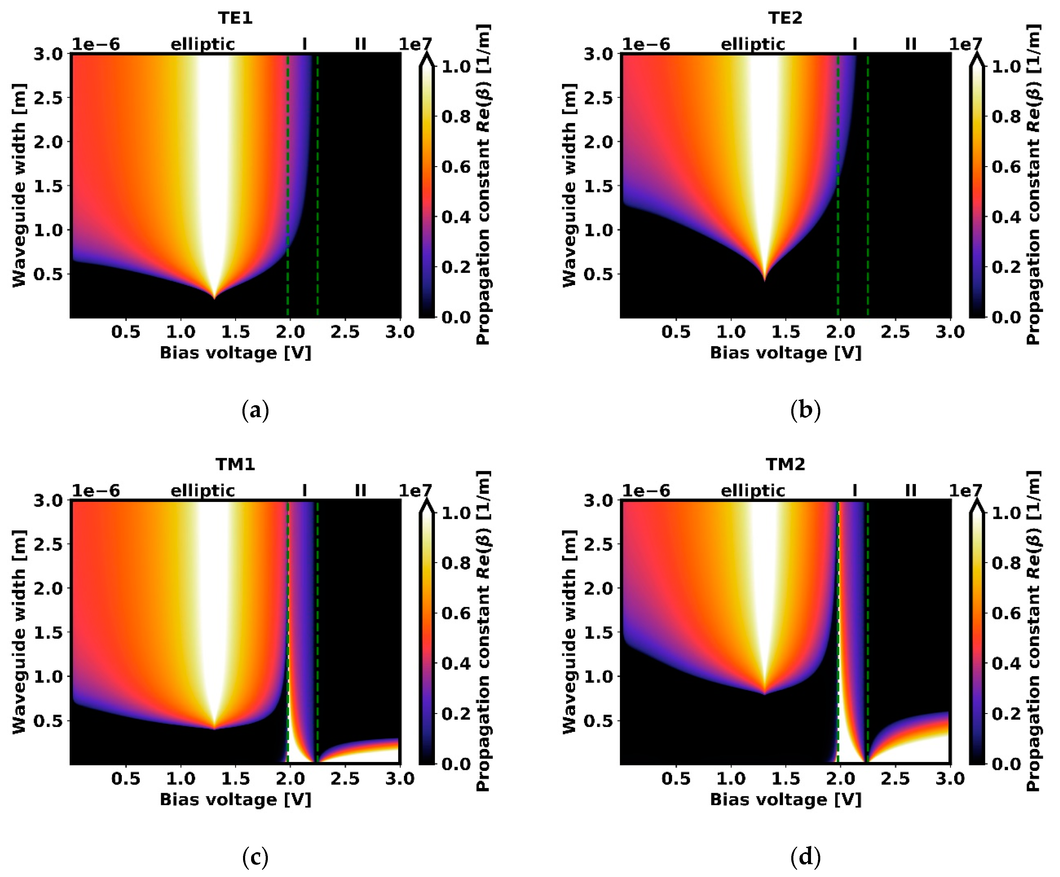
For broader insight into the waveguide propagation properties, “propagation maps” are presented, which illustrate the propagation constant as a function of the waveguide width and the biasing voltage, for TE and TM modes of the first and second order each (see Figure 4). The areas corresponding to dispersion regions of the guiding layer are indicated above the top bar of each plot (positive elliptic dispersion, abbreviated as elliptic; type I HMM, I; and type II HMM, II). At this time, we are still considering propagation properties at a fixed wavelength of 1.55 µm. Black areas indicate regions of no propagation, i.e., approximately where the imaginary part of β is greater than its real part.
Here, we can observe that TE modes (see Figure 4a,b) behave in elliptic and Type I HMM dispersion regions similarly as in a dielectric slab waveguide, which is consistent with the previously obtained characteristics (compare with Figure 3). In the Type II HMM region, however, the propagation is prohibited regardless of the waveguide width. This is due to the dispersion of metallic character exhibited by the guiding layer medium (see Figure 3e). Thus, for a waveguide of a given width, changing the biasing voltage allows for control over mode phase velocity, and the number of supported modes. We can distinguish two types of propagation control—(1) within the elliptic and type I HMM regions, when small biasing voltage changes are preferable, or (2) detuning to type II HMM for disabling propagation.
A more complex behavior can be observed in turn for TM modes, where each dispersion region is responsible, due to the arrangement of the electric field vector in xz-plane, for different propagation conditions (see Figure 4c,d). As a result, for a waveguide of a given width, it is possible to obtain propagation conditions for a certain mode order in the elliptic region, and at the same time, propagation of modes of higher orders in the Type I HMM region only. Finally, propagation in the Type II HMM region is always allowed, and it is worth noting that the power flow in this case is anti-parallel to the mode phase velocity. With all the aforementioned effects combined, a complete control of propagation with respect to mode phase velocity, power flow, and field confinement is obtained, which may be particularly suitable for optical signal processing, coupling control, signal modulation, or enhancement of nonlinear effects. There are two types of propagation control—within elliptic or type I HMM region, or between regions, depending on the chosen waveguide width.
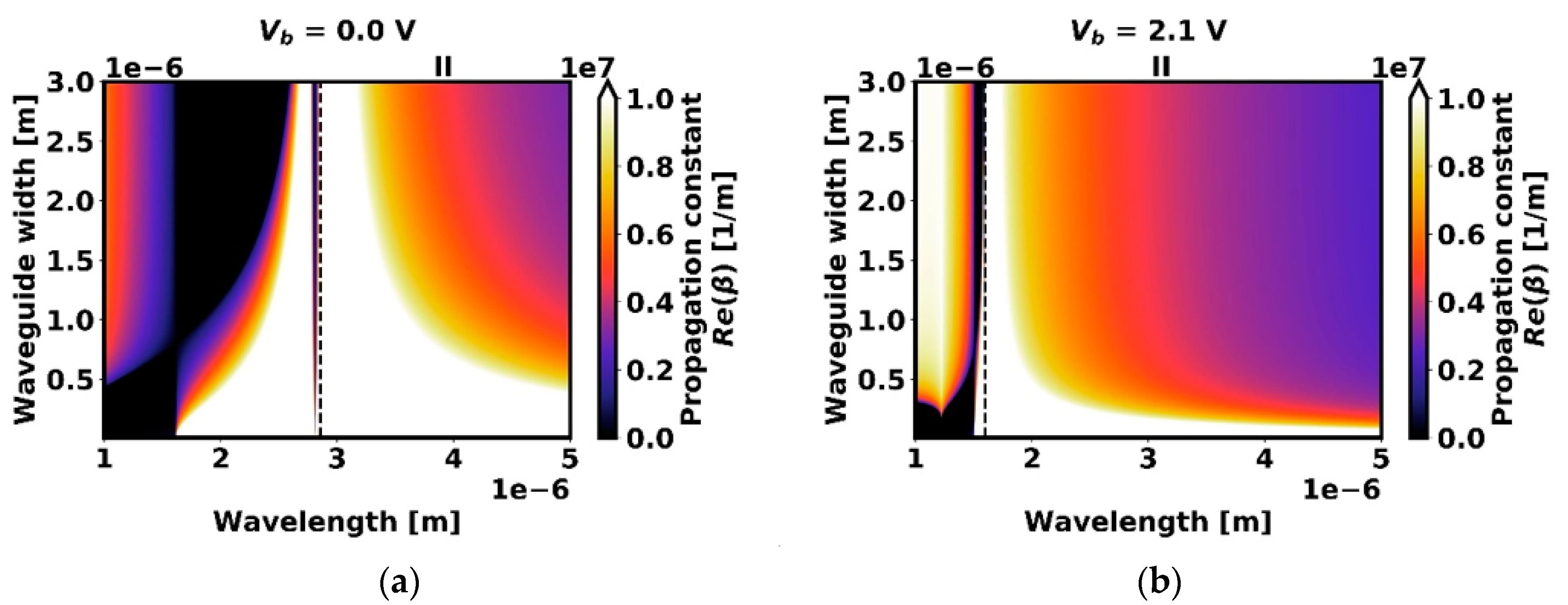
Qualitatively similar analysis can be performed in spectral domain by taking the perspective of fixed voltage biasing conditions (see Figure 5).
For a waveguide of a selected width, a mode of a given order at various wavelengths can either propagate freely (in regions of propagation window); be prohibited, resulting in “bandgap” regions (in black); or can have the power flow direction reversed with respect to phase velocity (in type II HMM dispersion region). As shown previously, the occurrence of these propagation regions in the spectral domain is dependent on the applied bias voltage. Additionally, the waveguide has the ability to propagate modes of much larger wavelengths than the width of the waveguide.

3.2. Results for Configuration B

We now consider propagation properties of the waveguide in configuration B (see Figure 1). As previously noted, fundamental modes of TE and TM polarizations do not exist due to the assumed boundary conditions. A similar analysis is conducted as in the case of configuration A. The change of configuration leads to the rearrangement of the components of the guiding layer effective permittivity tensor, where ε becomes εzz, and ε now corresponds to εxx and εyy (see Equation (9)).
When no biasing voltage is applied, again, the guiding layer medium exhibits positive elliptic dispersion. This time, however, TM and TE modes of a certain order reveal different cut-off widths, the behavior inherited after the effective anisotropy, see Figure 6a, which is evident from Equations (6) and (11) for β = 0. Thus, a behavior similar to that of the anisotropic slab waveguide is observed [51].
By changing the biasing voltage, the dispersion type of guiding layer medium becomes Type I hyperbolic (Vb = 2.1 V) (see Figure 6c). In this case, TM modes display behavior previously observed in Type II hyperbolic dispersion region, which is characterized by the absence of a cut-off width, and possible high energy confinement. Regardless of the rearrangement of the permittivity tensor followed by the change in waveguide configuration, TE modes preserve their performance observed for a dielectric waveguide, since these modes perceive the medium after the parallel tensor component ε.
A further increase of biasing voltage (Vb = 3 V) leads to Type II hyperbolic dispersion. Once more, propagation of TE modes, due to metallic character of the guiding medium, is prohibited (see Figure 6e). On the other hand, TM modes behave in an unusual manner, with a reversed cut-off, i.e., with increasing waveguide width, propagation of subsequent modes orders is being successively prohibited. Moreover, propagation in a waveguide of subwavelength width, where high energy confinement takes place, is still possible. For each mode order, there exists an optimal waveguide width for which the propagation distance is the largest. It is also worth noting, that the power flow of TM modes is contra-directional to phase velocity of the modes.
Analogously to analysis performed for configuration A, propagation maps for configuration B illustrating voltage-controlled behavior of TE and TM modes are presented (see Figure 7). In the case of TE polarization, modes perceive the same medium as in configuration A (compare with Figure 4a and 4b), so no change in propagation is expected nor observed.
In the case of TM modes, the waveguide of a given width provides propagation conditions for a certain mode order in type II HMM region, and at the same time, conditions for modes of higher orders in elliptic region. Propagation in the type I HMM region is always allowed. The power flow in the type II HMM region is contra-directional to phase velocity. Despite the differing characters of propagation in configurations A and B, both waveguides share a similar application potential, as discussed previously for configuration A, with regard to voltage-controlled propagation.
To provide qualitatively similar analysis as in the case of A configuration, we replicate characteristics for spectral domain (see Figure 8). Thus, for the considered waveguide of a given width, regions of propagation windows and gaps controlled with voltage are again observed.
All biasing conditions shown above result in a wide spectral bandwidth of operation of the class of waveguides considered.

4. Conclusions

Within this paper, we present a comprehensive analytical analysis of guiding conditions in metal-cladded THMM slab waveguides by example of a graphene-based multilayer nanostructure employed as a guiding layer. We demonstrate that their propagation properties can be controlled by means of the voltage-dependency of the dispersion type of the guiding medium. For comprehensiveness of the analysis, two configurations were presented, derived on the basis of the effective medium theory, where transformation of the effective permittivity tensor allowed us to straightforwardly account for two separate configurations. The structures constitute a new type of waveguides based on THMMs, combining effects previously observed in distinct waveguide configurations and offering a wide diversity of unusual propagation effects and flexibility of field distribution, which include permitting stopping, or breaking the propagation, as well as reversing the power flow with respect to phase velocity of the guided modes in a single, voltage-controlled nanostructure. We believe that such structures will find their applications in optical signal processing, controlled phase matching, coupling control, signal modulation, or enhancement of nonlinear effects by possible electric field confinement.

Author Contributions

Conceptualization, P.S.; methodology, P.S., M.K., and B.J.; software, M.K. and B.J.; formal analysis, A.T.-Z.; investigation, M.K. and B.J.; writing—original draft preparation, M.K. and B.J.; writing—review and editing, P.S.; visualization, M.K. All authors have read and agreed to the published version of the manuscript.

Funding

This research was funded by the National Centre for Research and Development, Poland, grant number TECHMATSTRATEG1/347012/3/NCBR/2017.

Conflicts of Interest

The authors declare no conflict of interest. The funders had no role in the design of the study; in the collection, analyses, or interpretation of data; in the writing of the manuscript, or in the decision to publish the results.

References

  1. Veselago, V.G. The electrodynamics of substances with simultaneously negative values of ε and µ. Sov. Phys. Uspekhi. 1968, 10, 509–514. [Google Scholar] [CrossRef]
  2. Pendry, J.B. Negative Refraction Makes a Perfect Lens. Phys. Rev. Lett. 2000, 85, 3966–3969. [Google Scholar] [CrossRef]
  3. Shadrivov, I.V.; Sukhorukov, A.A.; Kivshar, Y.S. Beam shaping by a periodic structure with negative refraction. Appl. Phys. Lett. 2003, 82, 3820–3822. [Google Scholar] [CrossRef] [Green Version]
  4. Alù, A.; Engheta, N. Achieving transparency with plasmonic and metamaterial coatings. Phys. Rev. E 2005, 72. [Google Scholar] [CrossRef] [PubMed] [Green Version]
  5. Shamonina, E.; Solymar, L. Metamaterials: How the subject started. Metamaterials 2007, 1, 12–18. [Google Scholar] [CrossRef]
  6. Shadrivov, I.V.; Sukhorukov, A.A.; Kivshar, Y.S. Guided modes in negative-refractive-index waveguides. Phys. Rev. E 2003, 67, 57602. [Google Scholar] [CrossRef] [Green Version]
  7. Wu, B.-I.; Grzegorczyk, T.M.; Zhang, Y.; Kong, J.A. Guided modes with imaginary transverse wave number in a slab waveguide with negative permittivity and permeability. J. Appl. Phys. 2003, 93, 9386–9388. [Google Scholar] [CrossRef]
  8. He, Y.; Cao, Z.; Shen, Q. Guided optical modes in asymmetric left-handed waveguides. Opt. Commun. 2005, 245, 125–135. [Google Scholar] [CrossRef]
  9. Wang, Z.; Dong, J. Analysis of Guided Modes in Asymmetric Left-Handed Slab Waveguides. Prog. Electromagn. Res. 2006, 62, 203–215. [Google Scholar] [CrossRef] [Green Version]
  10. D’Aguanno, G.; Mattiucci, N.; Scalora, M.; Bloemer, M.J. TE and TM guided modes in an air waveguide with negative-index-material cladding. Phys. Rev. E 2005, 71, 046603. [Google Scholar] [CrossRef]
  11. Wang, Z.H.; Xiao, Z.Y.; Li, S.P. Guided modes in slab waveguides with a left handed material cover or substrate. Opt. Commun. 2008, 281, 607–613. [Google Scholar] [CrossRef]
  12. Taya, S.A.; Qadoura, I.M. Guided modes in slab waveguides with negative index cladding and substrate. Opt. - Int. J. Light Electron Opt. 2013, 124, 1431–1436. [Google Scholar] [CrossRef]
  13. Lavoie, B.R.; Leung, P.M.; Sanders, B.C. Slow light with three-level atoms in metamaterial waveguides. Phys. Rev. A 2013, 88, 023860. [Google Scholar] [CrossRef] [Green Version]
  14. Tsakmakidis, K.L.; Boardman, A.D.; Hess, O. ‘Trapped rainbow’ storage of light in metamaterials. Nature 2007, 450, 397. [Google Scholar] [CrossRef]
  15. He, J.; He, S. Slow propagation of electromagnetic waves in a dielectric slab waveguide with a left-handed material substrate. Ieee Microw. Wirel. Compon. Lett. 2006, 16, 96–98. [Google Scholar] [CrossRef]
  16. Lu, W.T.; Huang, Y.J.; Casse, B.D.F.; Banyal, R.K.; Sridhar, S. Storing light in active optical waveguides with single-negative materials. Appl. Phys. Lett. 2010, 96, 211112. [Google Scholar]
  17. Zheng, G.; Ran, L. Light transmission along a slab waveguide with a core of anisotropic metamaterial. Opt. - Int. J. Light Electron Opt. 2008, 119, 591–595. [Google Scholar] [CrossRef]
  18. Jiang, T.; Zhao, J.; Feng, Y. Stopping light by an air waveguide with anisotropic metamaterial cladding. Opt. Express 2009, 17, 170. [Google Scholar] [CrossRef] [Green Version]
  19. Tang, T. Slow propagation of plasmonic modes in a symmetrical waveguide containing anisotropic metamaterial. Opt. - Int. J. Light Electron Opt. 2013, 124, 6119–6121. [Google Scholar] [CrossRef]
  20. Lu, W.T.; Sridhar, S. Slow light, open-cavity formation, and large longitudinal electric field on a slab waveguide made of indefinite permittivity metamaterials. Phys. Rev. A 2010, 82, 013811. [Google Scholar] [CrossRef] [Green Version]
  21. Neira, A.D.; Wurtz, G.A.; Zayats, A.V. Superluminal and stopped light due to mode coupling in confined hyperbolic metamaterial waveguides. Sci. Rep. 2015, 5, 17678. [Google Scholar] [CrossRef] [PubMed] [Green Version]
  22. Babicheva, V.E. Long-range propagation of plasmon and phonon polaritons in hyperbolic-metamaterial waveguides. J. Opt. 2017, 19, 124013. [Google Scholar] [CrossRef] [Green Version]
  23. Zeng, A.W.; Gao, M.X.; Guo, B. Slow light in a hyperbolic metamaterial waveguide cladded with arbitrary nonlinear dielectric materials. Appl. Phys. B 2018, 124, 146. [Google Scholar] [CrossRef]
  24. Babicheva, V.E.; Shalaginov, M.Y.; Ishii, S.; Boltasseva, A.; Kildishev, A.V. Finite-width plasmonic waveguides with hyperbolic multilayer cladding. Opt. Express 2015, 23, 9681. [Google Scholar] [CrossRef] [PubMed] [Green Version]
  25. Lyashko, E.I.; Maimistov, A.I. Linear guided waves in a hyperbolic planar waveguide. Dispersion relations. Quantum Electron. 2015, 45, 1050–1054. [Google Scholar] [CrossRef]
  26. Ishii, S.; Shalaginov, M.Y.; Babicheva, V.E.; Boltasseva, A.; Kildishev, A.V. Plasmonic waveguides cladded by hyperbolic metamaterials. Opt. Lett. 2014, 39, 4663. [Google Scholar] [CrossRef] [Green Version]
  27. He, Y.; He, S.; Yang, X. Optical field enhancement in nanoscale slot waveguides of hyperbolic metamaterials. Opt. Lett. 2012, 37, 2907. [Google Scholar] [CrossRef] [Green Version]
  28. Li, B.; He, Y.; He, S. Investigation of light trapping effect in hyperbolic metamaterial slow-light waveguides. Appl. Phys. Express 2015, 8, 082601. [Google Scholar] [CrossRef]
  29. Hu, H.; Ji, D.; Zeng, X.; Liu, K.; Gan, Q. Rainbow Trapping in Hyperbolic Metamaterial Waveguide. Sci. Rep. 2013, 3, 1249. [Google Scholar] [CrossRef]
  30. Zhang, L.; Zhang, Z.; Kang, C.; Cheng, B.; Chen, L.; Yang, X.; Wang, J.; Li, W.; Wang, B. Tunable bulk polaritons of graphene-based hyperbolic metamaterials. Opt. Express 2014, 22, 14022. [Google Scholar] [CrossRef]
  31. Xiang, Y.; Guo, J.; Dai, X.; Wen, S.; Tang, D. Engineered surface Bloch waves in graphene-based hyperbolic metamaterials. Opt. Express 2014, 22, 3054. [Google Scholar] [CrossRef] [PubMed]
  32. Othman, M.A.K.; Guclu, C.; Capolino, F. Graphene-Dielectric Composite Metamaterials: Evolution from Elliptic to Hyperbolic Wavevector Dispersion and The Transverse Epsilon-Near-Zero Condition. J. Nanophotonics 2013, 7, 073089. [Google Scholar] [CrossRef] [Green Version]
  33. Hajian, H.; Ghobadi, A.; Dereshgi, S.A.; Butun, B.; Ozbay, E. Hybrid plasmon–phonon polariton bands in graphene–hexagonal boron nitride metamaterials [Invited]. J. Opt. Soc. Am. B 2017, 34, D29. [Google Scholar] [CrossRef] [Green Version]
  34. Bhuyan, M.S.A.; Uddin, M.N.; Bipasha, F.A.; Islam, M.M.; Hossain, S.S. A Review of Functionalized Graphene properties and its application. Int. J. Innov. Sci. Res. 2015, 17, 303–315. [Google Scholar]
  35. Guo, B.; Fang, L.; Zhang, B.; Gong, J.R. Graphene Doping: A Review. Insciences J. 2011, 1, 80–89. [Google Scholar] [CrossRef] [Green Version]
  36. Zhu, B.; Ren, G.; Zheng, S.; Lin, Z.; Jian, S. Nanoscale dielectric-graphene-dielectric tunable infrared waveguide with ultrahigh refractive indices. Opt. Express 2013, 21, 17089. [Google Scholar] [CrossRef] [PubMed]
  37. Sayem, A.A.; Mahdy, M.R.C.; Hasan, D.N.; Matin, M.A. Tunable slow light with graphene based hyperbolic metamaterial. In Proceedings of the 8th International Conference on Electrical and Computer Engineering, Piscataway, NJ, USA, 20–22 December 2014; IEEE: Dhaka, Bangladesh, 2014; pp. 230–233. [Google Scholar]
  38. Zhu, B.; Ren, G.; Gao, Y.; Yang, Y.; Wu, B.; Lian, Y.; Jian, S. Local Field Enhancement in Infrared Graphene- Dielectric Hyperbolic Slot Waveguides. IEEE Photonics Technol. Lett. 2015, 27, 276–279. [Google Scholar] [CrossRef]
  39. Tyszka-Zawadzka, A.; Janaszek, B.; Szczepański, P. Tunable slow light in graphene-based hyperbolic metamaterial waveguide operating in SCLU telecom bands. Opt. Express 2017, 25, 7263. [Google Scholar] [CrossRef] [PubMed]
  40. Choy, T.C. Effective Medium Theory: Principles and Applications, International Series of Monographs on Physics; 2nd ed.; Oxford University Press: Oxford, UK, 2016; ISBN 978-0-19-870509-3. [Google Scholar]
  41. Janaszek, B.; Tyszka-Zawadzka, A.; Szczepański, P. Tunable graphene-based hyperbolic metamaterial operating in SCLU telecom bands. Opt. Express 2016, 24, 24129. [Google Scholar] [CrossRef]
  42. Hanson, G.W. Dyadic Green’s Functions for an Anisotropic, Non-Local Model of Biased Graphene. IEEE Trans. Antennas Propag. 2008, 56, 747–757. [Google Scholar] [CrossRef]
  43. Maharana, P.K.; Jha, R.; Palei, S. Sensitivity enhancement by air mediated graphene multilayer based surface plasmon resonance biosensor for near infrared. Sens. Actuators B Chem. 2014, 190, 494–501. [Google Scholar] [CrossRef]
  44. Gómez-Díaz, J.S.; Perruisseau-Carrier, J. Graphene-based plasmonic switches at near infrared frequencies. Opt. Express 2013, 21, 15490. [Google Scholar] [CrossRef] [PubMed] [Green Version]
  45. Rodrigo, D.; Limaj, O.; Janner, D.; Etezadi, D.; Garcia de Abajo, F.J.; Pruneri, V.; Altug, H. Mid-infrared plasmonic biosensing with graphene. Science 2015, 349, 165–168. [Google Scholar] [CrossRef] [Green Version]
  46. Zhao, X.; Zhu, L.; Yuan, C.; Yao, J. Tunable plasmon-induced transparency in a grating-coupled double-layer graphene hybrid system at far-infrared frequencies. Opt. Lett. 2016, 41, 5470. [Google Scholar] [CrossRef] [PubMed]
  47. Higuchi, M.; Takahara, J. Plasmonic interpretation of bulk propagating waves in hyperbolic metamaterial optical waveguides. Opt. Express 2018, 26, 1918. [Google Scholar] [CrossRef] [PubMed]
  48. Maier, S.A. Plasmonics: Fundamentals and Applications; Springer: New York, NY, USA, 2007; ISBN 978-0-387-33150-8. [Google Scholar]
  49. Kaminow, I.P.; Mammel, W.L.; Weber, H.P. Metal-Clad Optical Waveguides: Analytical and Experimental Study. Appl. Opt. 1974, 13, 396. [Google Scholar] [CrossRef] [PubMed]
  50. Huang, Y.J.; Lu, W.T.; Sridhar, S. Nanowire waveguide made from extremely anisotropic metamaterials. Phys. Rev. A 2008, 77, 063836. [Google Scholar] [CrossRef] [Green Version]
  51. Satomura, Y.; Matsuhara, M.; Kumagai, N. Analysis of Electromagnetic-Wave Modes in Anisotropic Slab Waveguide. IEEE Trans. Microw. Theory Tech. 1974, 22, 86–92. [Google Scholar] [CrossRef]
Figure 1. Schematic representation of two waveguide configurations under investigation, configuration A (left) and configuration B (right), where tg and td are widths of graphene and dielectric layers, and σ is the conductivity of a perfectly metallic layer.
Crystals 10 00176 g001
Figure 2. Effective permittivity tensor components of the guiding medium at 1.55 µm dependent on the voltage bias Vb applied. Three dispersion regions are indicated: positive elliptic (0 < Vb < 1.98 V), type I hyperbolic metamaterial (HMM) (1.98 V < Vb < 2.25 V) and type II HMM (Vb > 2.25 V).
Crystals 10 00176 g002
Figure 3. Propagation constant for configuration A at 1.55 µm in various dispersion regimes, dependent on the voltage bias Vb applied: (a,b) positive elliptic (0 V), (c,d) Type I HMM (2.1 V), and (e,f) Type II HMM (3 V). Power flow direction is indicated.
Crystals 10 00176 g003
Figure 4. Propagation constant for configuration A as a function of the waveguide width d and the applied bias voltage Vb, at 1.55 µm for first and second order TE (a,b) and TM (c,d) modes. Black areas indicate regions where propagation is forbidden.
Crystals 10 00176 g004
Figure 5. Map of propagation constant values for TM1 in configuration A at various bias voltages: (a) 0 V and (b) 2.1 V. Type II HMM dispersion region is indicated.
Crystals 10 00176 g005
Figure 6. Propagation constant for configuration B at 1.55 µm in various dispersion regions, dependent on the voltage bias Vb applied: (a,b) positive elliptic (0 V), (c,d) Type I HMM (2.1 V), and (e,f) Type II HMM (3 V). Power flow direction is indicated in each plot.
Crystals 10 00176 g006
Figure 7. Map of propagation constant values for TM1 and TE1 (a,c), and TM2 and TE2 (b,d) for a perpendicular configuration at 1.55 µm dependent on the waveguide width the biasing voltage. Black areas indicate regions where propagation is prohibited.
Crystals 10 00176 g007
Figure 8. Map of propagation constant values for TM1 for a configuration B at various bias voltages: (a) 0 V and (b) 2.1 V. Type II HMM is indicated. Black areas indicate regions where propagation is prohibited.
Crystals 10 00176 g008