Article

Microstructural Stability and Softening Resistance of a Novel Hot-Work Die Steel

1
Shenyang National Laboratory for Materials Science, Institute of Metal Research, Chinese Academy of Sciences, Shenyang 110016, China
2
School of Materials Science and Engineering, University of Science and Technology of China, Hefei 230026, China
*
Authors to whom correspondence should be addressed.
Crystals 2020, 10(4), 238; https://doi.org/10.3390/cryst10040238
Submission received: 7 March 2020 / Revised: 23 March 2020 / Accepted: 24 March 2020 / Published: 25 March 2020
(This article belongs to the Special Issue Microstructural and Mechanical Characterization of Alloys)

Abstract

:
A novel hot-work die steel, named 5Cr5Mo2, was designed to obtain superior thermal stability. The proposed alloy is evaluated in terms of its hardness, microstructure, and tempering kinetics. Compared with the commonly used H13 steel, the softening resistance of the designed steel is superior. Based on SEM and transmission electron microscopy (TEM) observations, a higher abundance of fine molybdenum carbides precipitate in 5Cr5Mo2 steel. Strikingly, the coarseness rate of the carbides is also relatively low during the tempering treatment. Moreover, owing to their pinning effect on dislocation slip, the dislocation density of the 5Cr5Mo2 steel decreases more slowly than that of the H13 steel. Furthermore, a mathematical softening model was successfully deduced and verified by analyzing the tempering kinetics. This model can be used to predict the hardness evolution of the die steels during the service period at high temperature.

1. Introduction

Hot-work die steels are steel alloys that are suitable for manufacturing dies for the hot deformation of metals, such as hot extrusion dies, hot-forging dies, hot upsetting dies, and die-casting dies. Hot-work die steel alloys are commonly used to produce tools that are exposed to high temperatures and are usually alloyed with strong carbide forming elements such as Cr, Mo, and V [1,2]. Hot-forming is a reliable and relatively economical manufacturing process for metal parts, which relies on high-quality hot-work dies. During hot-forming, regions of the tools may attain high temperatures or pressures, especially regions of the die tool that exhibit a small radii in the die cavities [3]. Because hot-forming dies are exposed to high temperatures and pressures for prolonged periods, the die materials are required to exhibit high strength, hardness, particularly high thermal strength, thermal fatigue, toughness, and wear resistance. The risk of encountering various failure modes drastically increases the probability of the properties of the selected tool material to not meet the service conditions. Consequently, the manufacturing costs can be significantly increased [4]. A general requirement of steel alloys with better thermal stability is that their microstructure and hardness are not likely to rapidly change at high temperatures. Thus, the thermal stability of an alloy, which is a crucial property influencing the service life of hot-work die steel alloys, must be considered before the alloy is used for engineering applications.
Earlier investigations [5,6,7] of hot-work die steel alloys have shown that the thermal stability during tempering is strongly associated with the microstructure and the alloy carbide precipitates. The typical microstructure of hot-work die steel alloys after conventional quenching and tempering procedures consists of tempered martensite with solid solution of carbon, high dislocation density, and fine alloy carbide precipitates. Nevertheless, a prolonged tempering treatment results in the softening of steel alloys, which is mainly caused by the coarsening of the fine alloy carbides, reduction of the dislocation density, and recovery of the martensitic structure [6,8,9]. By observing the microstructure of low-carbon martensitic steels, A. Arlazarov [10] showed the precipitation of carbides caused by tempering. The amount and size of precipitates is significantly influenced by carbide-forming elements (W, Mo, Nb, V) [11]. D. Delagnes et al. [12] explained the influence of the silicon content on the amount of carbides in a 5%Cr tempered martensitic steel.
Hot-forming dies are used in high-temperature environments, which can be regarded, to some extent, as a prolonged tempering process. During tempering, carbon atoms eject from the supersaturated martensite, consequently causing the reduction of the strength of steel alloys [13]. The martensite tempering process is influenced by tempering temperature [14], and tempering time [15,16]. The effects of chemical composition and the heat treatment parameters on the microstructure and properties of die steel alloys have been extensively studied [17,18,19]. However, the microstructural stability and softening resistance of hot-work die steel alloys during long-term operation in the high-temperature situation have seldom been focused on.
In this study, we designed a novel 5Cr5Mo2 steel alloy based on the most common hot-work H13 die steel. The thermal stability of the proposed alloy was systemically determined based on its microstructure, hardness, and tempering kinetics. The main factors affecting the softening and the mechanism of the softening during tempering were clarified. Most importantly, a mathematical model describing the softening behavior of the alloy was successfully built.

2. Materials and Experiments

2.1. Materials and Heat Treatment

5Cr5Mo2 and H13 hot-work die steel samples were produced using vacuum induction melting. The chemical composition of the two steel alloys is given in Table 1. All samples for this experiment were obtained by wire electrical machining from a single ingot after forging along the three orthogonal directions.
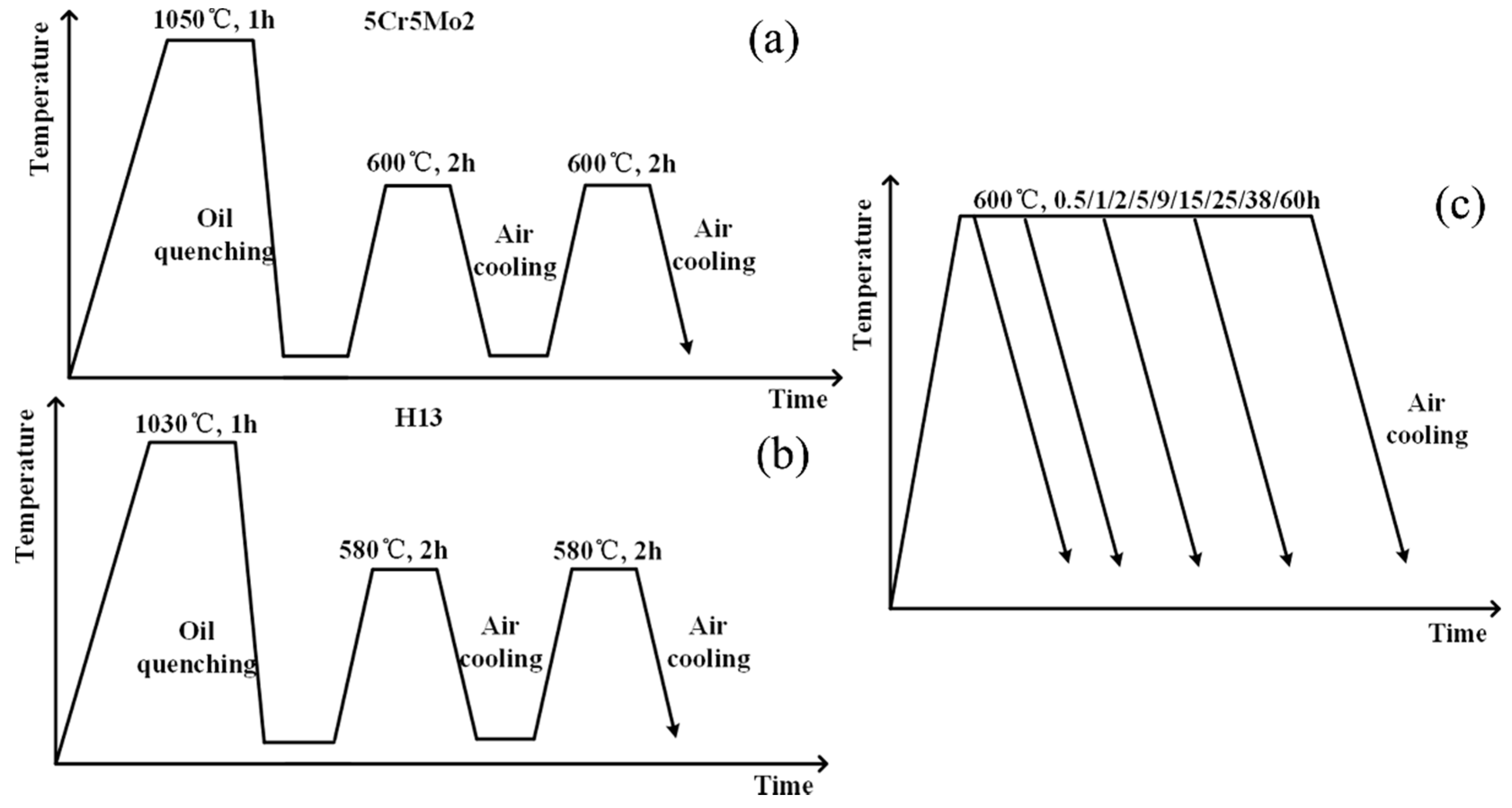
In order to obtain the service microstructure and set the hardness of two steel alloys to a similar value, the samples used for thermal stability tests were subjected to a pre-heat-treatment process consisting of quenching and tempering. Our previous experiments showed that, the hardness and Charpy un-notched impact energy of 5Cr5Mo2 were the highest with an austenitizing temperature of 1050 °C, and its Charpy V-notch impact energy is slightly smaller than that at the lower temperatures, as shown in Figure 1a–c. When a tempering temperature of 600 °C is then applied, the hardness reaches 49.8 HRC (see Figure 1d), which is close to the follow-up experimental requirements, making the hardness of two steel alloys to a similar value and obtaining an excellent performance in the 5Cr5Mo2 steel. Hence, in this study, the 5Cr5Mo2 steel was heated at an austenitizing temperature of 1050 °C for 1 h and oil quenched. Subsequently, the samples were tempered at 600 °C for 2 h, followed by air cooling (Figure 2a). In terms of the H13 steel, the common heat treatment parameters were used as shown in Figure 2b. For instance, the H13 steel was heated at an austenitizing temperature of 1030 °C for one hour and oil quenched. Subsequently, the samples were tempered at 580 °C for 2 h, and then air-cooled. The tempering process was repeated two times. It should be stressed that, the choice of a lower quenching temperature (1030 °C) for H13 steel is because that, more undissolved VC carbides play an important role in refining grains during quenching. Such heat treatment process is commonly used in engineering practice.
To obtain the evolution of the thermal stability in high-temperature service conditions—such as hardness and characteristics of the microstructure—an additional tempering was performed at 600 °C which is the typical working temperature of forging dies. The additional tempering process is shown in Figure 2c. This secondary tempering lasted various durations: {0.5, 1, 2, 5, 9, 15, 25, 38, 60} h. The tempering was followed by air cooling. Samples with dimensions of 12 mm × 12 mm × 10 mm were prepared for thermal stability tests. In order to prevent oxidation during the heat treatment, all samples were sealed in quartz tubes filled with argon.

2.2. Mechanical Tests

Rockwell hardness was measured in a Wilson Rockwell device (LCR–500, LECO Company) according to the standard ASTM E18-2017. Samples with dimensions of 12 mm × 12 mm × 10 mm prior to the pre-treatment were prepared through tempering, whose duration varied among the samples to investigate the influence of the tempering duration.

2.3. Microstructure Observations

The microstructure characteristics of the 5Cr5Mo2 and H13 specimens were investigated by scanning electron microscopy (Inspect F50, FEI) and transmission electron microscopy (TEM) (Tecnai Spirit TEM T12, FEI and Tecnai G2 20, FEI). The transmission electron microscopy samples with a diameter of 3 mm and thickness of 50 μm were thinned by twin-jet electropolishing in a 6 vol.% perchloric acid/ethanol solution at a voltage of 25 V and a temperature between −30 °C and −25 °C.

2.4. X-ray Diffraction Analysis

X-ray diffraction (XRD) (D8 Advance, Bruker) analysis was performed using incidence angles of 40°–100° for the solid bulk samples and incidence angles of 20°–85° for the carbide powder extracted from the solid samples at room temperature using Cu-Kα radiation. The solid bulk samples used for the dislocation density measurements were prepared by the electro-polishing method in order to prevent the presence of residual stresses that appeared during mechanical polishing. The second phase particles of the two steel alloys were characterized by electrolytic extraction in a 10 vol.% hydrochloric acid/methanol solution. The samples for extraction were taken after the pre-heat-treatment. The dislocation density and types of second phase particles were determined by analyzing the XRD patterns via the MDI Jade 6.5 software. The microstrain and the full width at half-maximum intensity (FWHM) of the selected peaks were determined by the Williamson–Hall method [20]. The dislocation density values were calculated from the microstrain by the Williamson–Hall equation [5,21,22,23].

3. Results and Discussion

3.1. Alloy Design

V and Mo are strong carbide forming elements which are commonly used for tool steel alloys. Both V and Mo are effective strengthening elements. Molybdenum plays an important role in retarding the coarsening of nano-sized carbides and inhibiting the annihilation of dislocations at elevated tempering temperatures [24,25]. Steel alloys with Mo additions exhibit longer retention of their mechanical properties during high-temperature aging [26,27,28]. Hence, during the design of the proposed steel alloy, the Mo content of the steel was adjusted from 1.35 wt.% to 2.48 wt.% to obtain finer carbides and enhanced characteristics. On the contrary, V-rich MC particles can coarsen during hot rolling or during the subsequent annealing heat treatment, thus, leading to the significant degradation of the strength of the materials. Moreover, it was shown that large primary vanadium carbide particles are formed in H13 steel, which is detrimental to the steel’s properties. Considering the detrimental effect and material cost, the V content of the steel was reduced.
Carbon atoms present in steels either form a solid solution in the steel matrix or participate in the formation of carbides. Carbon increases the strength and hardness of the steel but reduces its toughness. Therefore, the carbon content of the proposed alloy was increased to ensure sufficient hardness in high-temperature environments, while keeping it appropriately low to avoid a serious decrease in toughness. Silicon also significantly affects the properties of steel by increasing the quantity and stability of the retained austenite [24]. However, the transformation of austenite to martensite would deteriorate the dimensional accuracy of the produced dies and the machining performance of the steels [29]. Thus, a high retained austenite fraction is generally avoided in hot-work die steel alloys. Consequently, the Si content of the proposed 5Cr5Mo2 steel is moderately reduced. The chemical composition of the two target alloys considered is shown in Table 1.
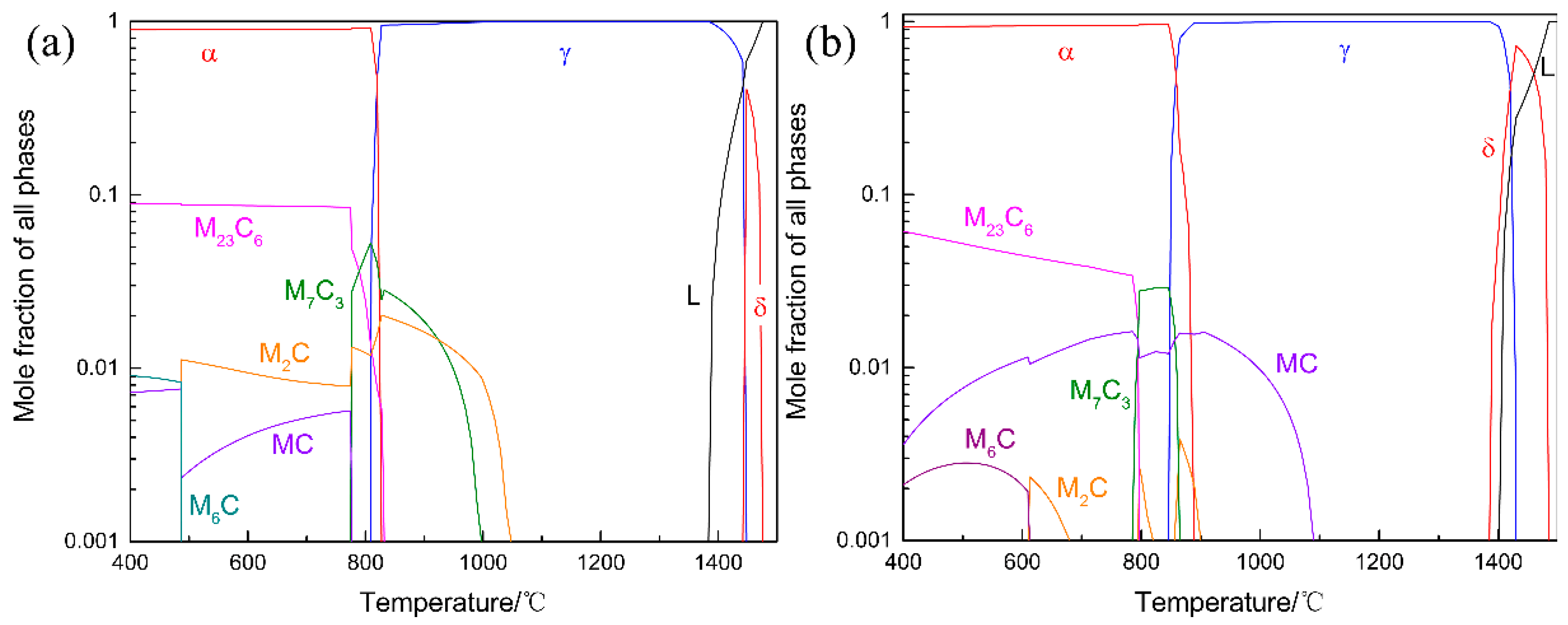
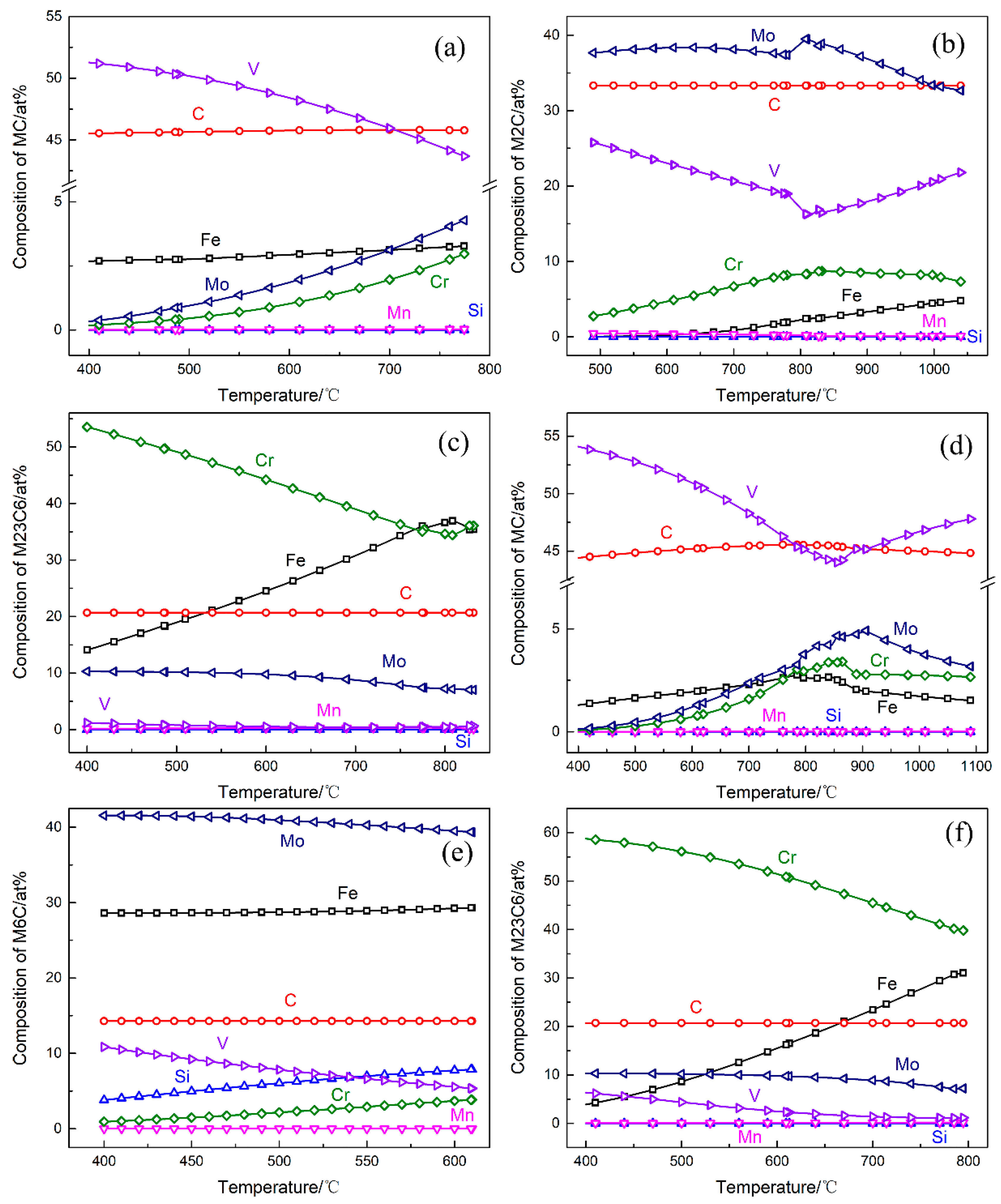
The Thermo-Calc software was used to carry out thermodynamic calculations to guide the alloy design and to plan the follow-up experimental study. The subsequent thermal stability tests were carried out at the temperature of 600 °C, and the liquidus temperature of the two considered steel alloys is below 1500 °C. Consequently, the temperature range selected for the calculations was 400–1500 °C. The results of the calculations are shown in Figure 3. The main equilibrium precipitation phases in the 5Cr5Mo2 steel are MC, M2C, M7C3, M6C, and M23C6. There are the same types of equilibrium precipitation phases that are present in the H13 steel. The temperature-dependent behavior of certain precipitation phases exhibits sudden changes. This is caused by the change of carbide types, which are present in the steel in a non-equilibrium state for a prolonged duration. After keeping the H13 steel at the tempering temperature of 600 °C, MC, M23C6, and M6C exist stably, while M2C and M7C3 dissolve or transform into other phases. On the contrary, the stable phases in the 5Cr5Mo2 steel are MC, M2C, and M23C6, while M7C3 and M6C are unstable at 600 °C. The composition of these phases was also calculated by the Thermo-Calc software. The variation curves of the constituting elements (in at. %) of the relevant phases are shown in Figure 4 for a temperature range of 400–1500 °C: MC, M2C, M23C6, and M6C are V-rich, Mo-rich, Cr-rich, and Mo-rich phases, respectively. There are four stable phases in the 5Cr5Mo2 steel at 600 °C: α, MC, M23C6, and M2C with a mole fraction of 90.0%, 0.4%, 8.7%, and 0.9%, respectively. Conversely, the mole fractions of α, MC, M23C6, and M6C in the H13 steel are 94.2%, 4.5%, 1.1%, and 0.2%, respectively. These results are consistent with the intended alloy design.

3.2. Mechanical Properties

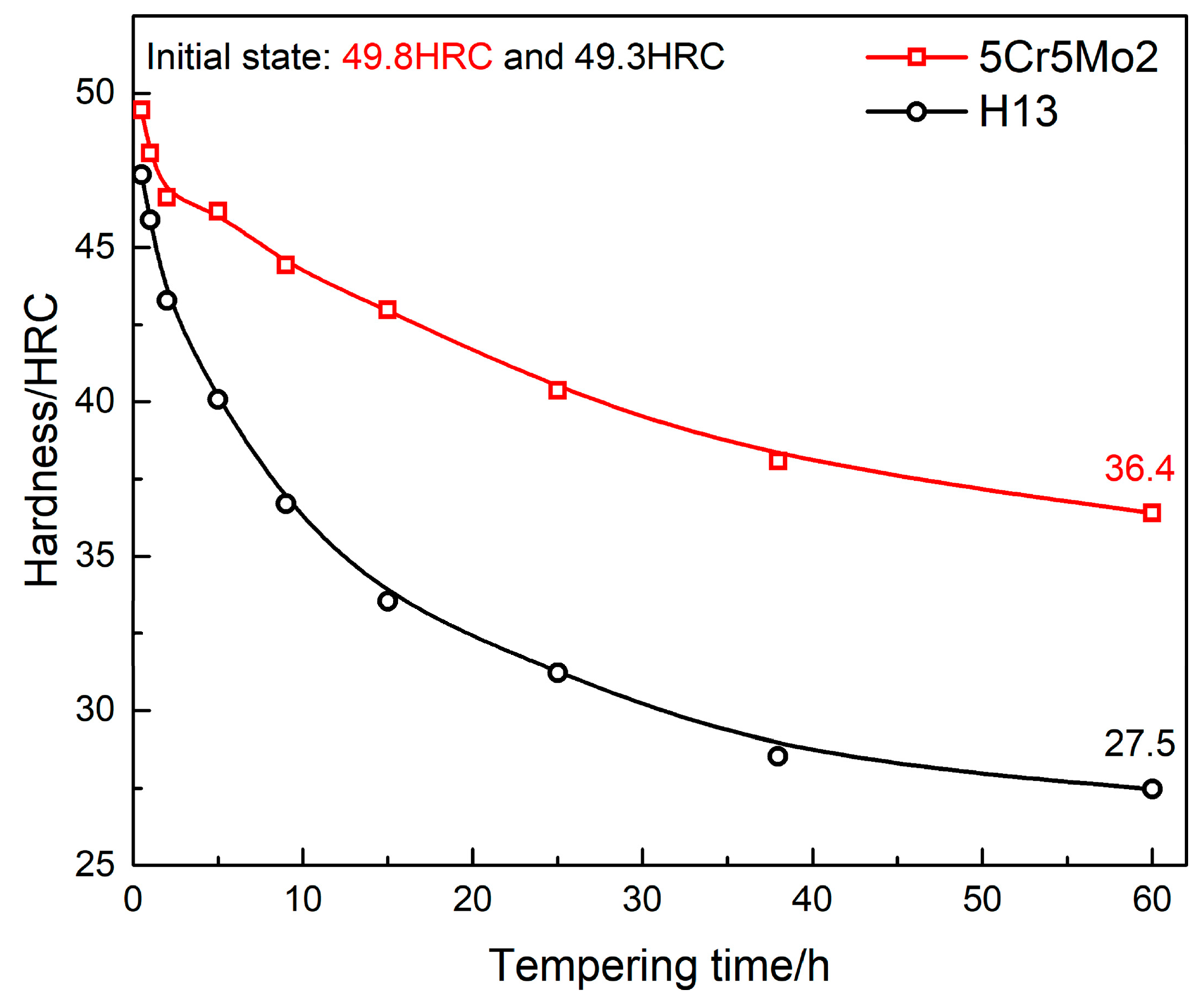
The hardness of the 5Cr5Mo2 and H13 steel alloys as a function of the tempering duration is shown in Figure 5. The hardness of both steel alloys decreases as the tempering duration increases. Nevertheless, the hardness of the H13 steel decreases faster than that of the 5Cr5Mo2 steel. The hardness of the 5Cr5Mo2 steel decreases from 49.8 HRC to 36.4 HRC. At the same time, the hardness of the H13 steel decreases from 49.3 HRC to 27.3 HRC after 60 h of tempering at 600 °C. In addition, a sharp decrease in hardness of the two steel alloys occurs during the initial stage of tempering. On the contrary, the softening rate decreases with the increased tempering duration. For comparison, the softening rate of the H13 steel is faster than that of the 5Cr5Mo2 steel. However, the softening rate of both alloys decreases with the increasing tempering duration. That is, the softening resistance of the 5Cr5Mo2 steel is higher than that of the H13 steel and the designed steel exhibits better thermal stability.

3.3. Microstructure

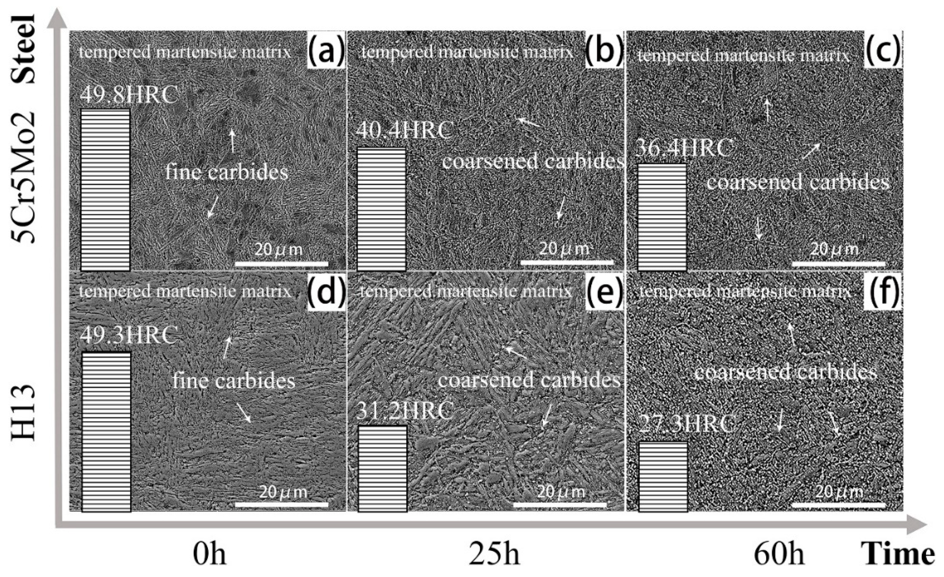
The softening of the 5Cr5Mo2 and H13 steel alloys during tempering is strongly linked to their microstructure. Most alloying elements dissolve into the matrix during quenching and separate from the martensite matrix during tempering, which plays a significant role in dispersion strengthening. Correspondingly, the microstructure of the two steel alloys after the pre-heat-treatment without additional tempering mainly consists of tempered martensite and a small number of fine alloy carbides, as shown in Figure 6a,d. After tempering for 25 h and 60 h, the fine carbides appear significantly coarsened, and the martensite matrix is recovered in both steel alloys, as shown in Figure 6b,c,e,f. However, by comparing the structures of the two steel alloys, it can be observed that the modification of the tempered martensitic lath of the 5Cr5Mo2 alloy is relatively small compared with that of the H13 steel. Thus, it can be concluded that the martensite of the designed steel is more stable than that of the H13 steel.
In essence, steel softening is the degradation of multiple reinforcing effects, such as solid solution strengthening, and precipitation strengthening after the tempering process. The strengthening mechanisms of martensite achieved by quenching have been already summarized elsewhere [30], including the substitutional and interstitial solid solutions, dislocation strengthening, segregation of carbon atoms, and precipitation of carbides. After the tempering treatment, the strengthening effect of the martensite structure is significantly reduced [24,30]. The softening of hot-work die steel alloys mainly depends on the recovery of dislocations and the coarsening of alloy carbides at high temperatures [30]. Kelly et al. [31] considered that although the segregation of carbon reduces the stress field of the dislocations, it plays a more significant role in pinning dislocations, consequently increasing the strength of the alloy after tempering. On the contrary, carbides precipitate at dislocations, which is why the strength of martensite is shown to increase at room temperature or just above room temperature [30]. Thus, the factors influencing martensite stability and the difference between these factors in the two steel alloys were analyzed based on the characteristics of carbides and dislocations.
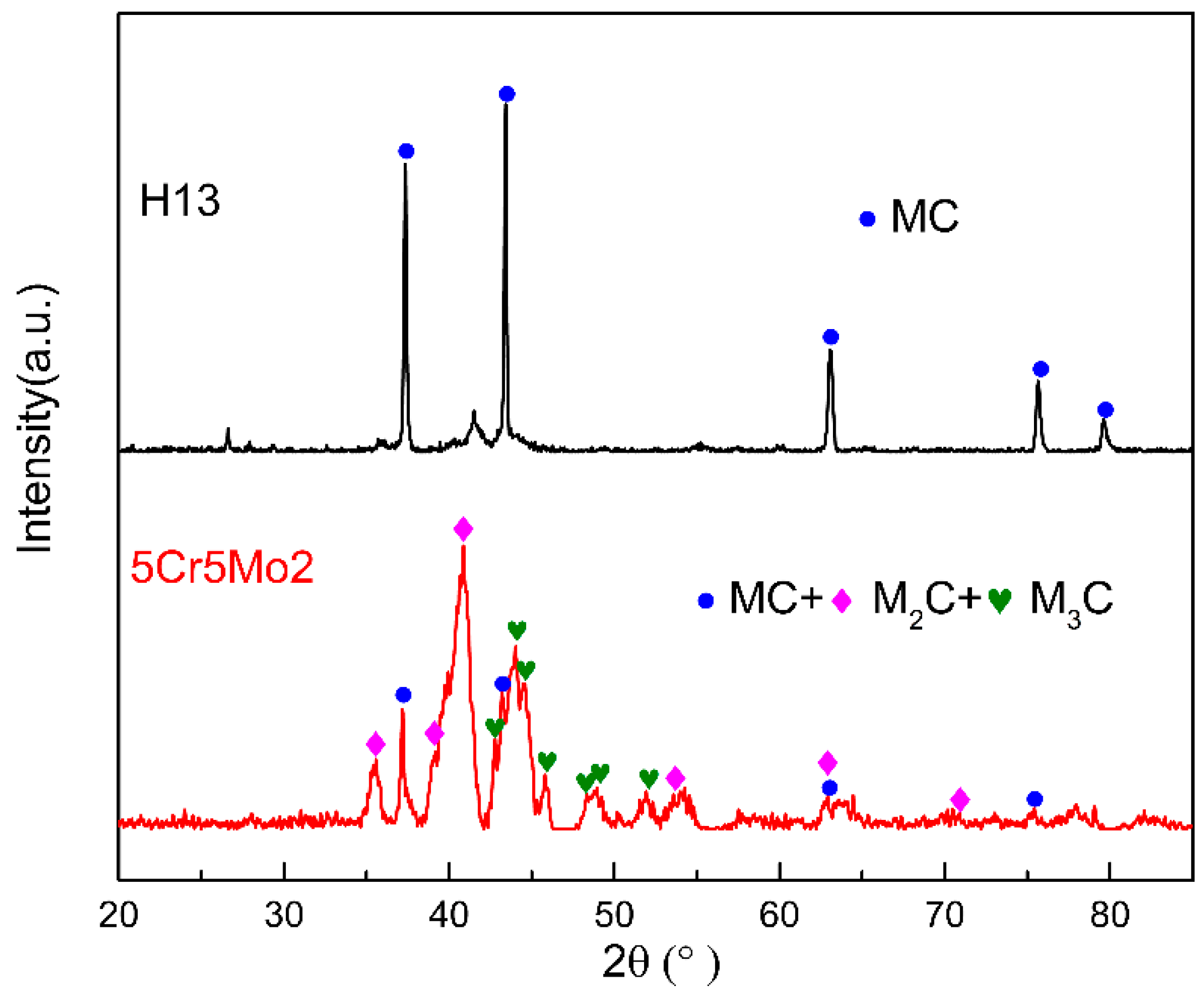
High-magnification SEM and TEM observations were performed to obtain more detailed information about the steels’ microstructures. Figure 7 shows the microstructure of both steel alloys after no additional tempering. The matrices of both steel alloys are tempered martensite. In the 5Cr5Mo2 steel, the most abundant carbides are elliptical-shaped vanadium carbides and fine needle-shaped molybdenum carbides, as shown in Figure 7b,c. Conversely, there are some large size primary carbides found in the H13 steel, as shown in Figure 7f,g. Those carbides are vanadium carbides identified by their diffraction (Figure 7h) and energy spectra (Figure 7i). The second carbides are mainly vanadium carbides. XRD measurements were also performed on carbide powders extracted from the solid samples. The XRD results (Figure 8) were consistent with the TEM observations.
The fine molybdenum and vanadium carbides are conducive to the thermal stability, but the large size primary carbides are detrimental for the toughness. The designed steel, with higher molybdenum and lower vanadium content, effectively avoids the formation of large size primary carbides and promotes the formation of fine molybdenum carbides. Moreover, molybdenum carbides are usually fine and coarsen slowly in steel alloys [32]. Based on the comparison of the carbides present in the two steel alloys (Figure 7), it can also be concluded that more carbides precipitate in the 5Cr5Mo2 steel because of its higher carbon content.
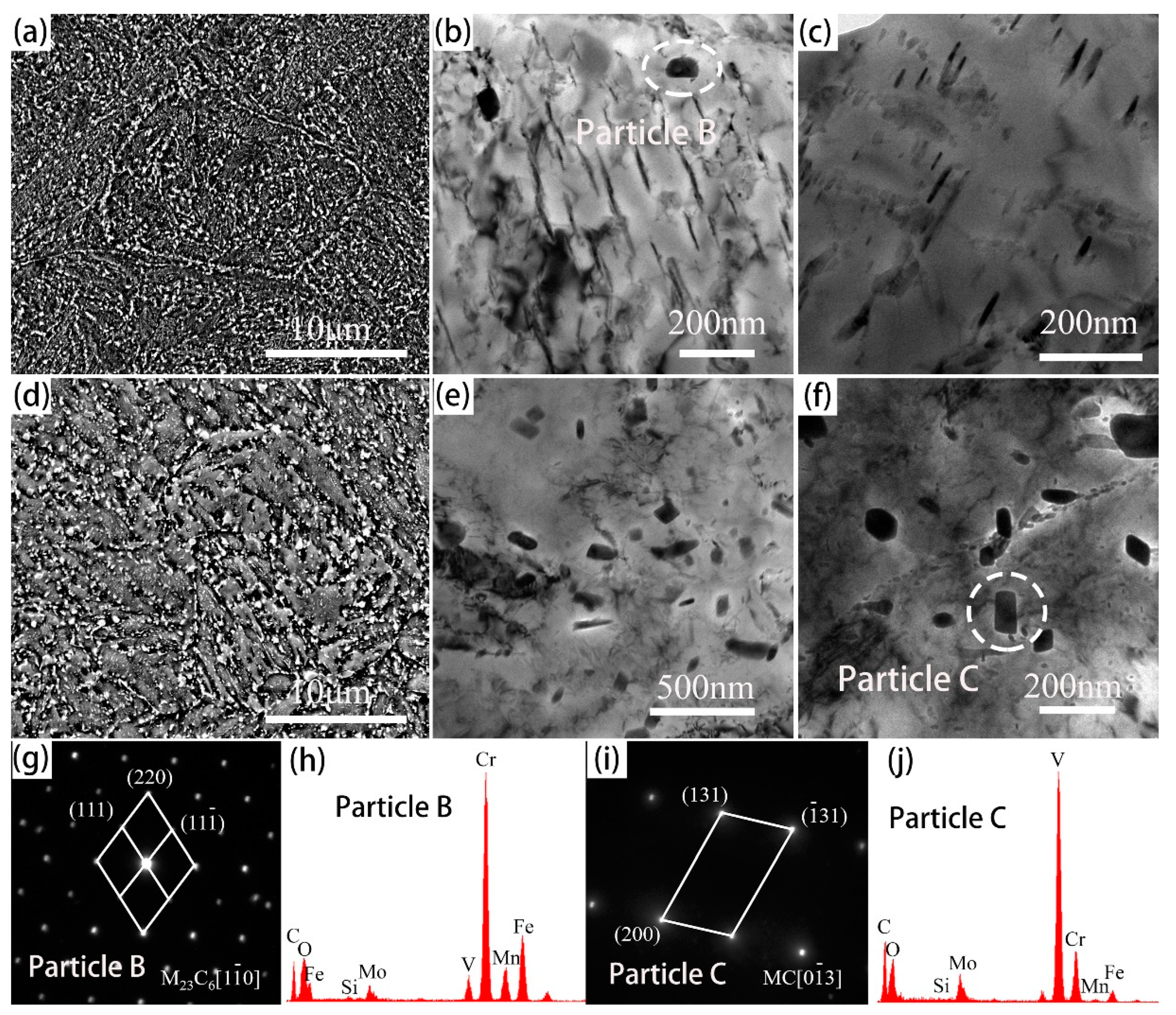
The evolutions of the tempered martensite and carbides after additional tempering duration of 60 h are shown in Figure 9 for both steel alloys. Figure 9a,d show the widened martensite and coarsened carbides in both steel alloys observed by SEM. Although martensite recovery and carbide coarsening occur in both alloys, a difference between the designed steel and the H13 steel can be observed. The carbides in the 5Cr5Mo2 steel are predominantly elliptical-shaped and bar-like carbides, as observed by TEM (Figure 9b,c). An elliptical-shaped carbide (particle B) was further investigated by its diffraction (Figure 9g) and energy spectra (Figure 9h). The measurements suggest that particle B is a Cr-rich M23C6 type carbide. TEM observations show that large-size carbides are abundant in the H13 steel, as shown in Figure 9e,f. The size of the largest observed secondary carbide exceeded 200 nm. The carbides are mainly vanadium carbides, as identified by their diffraction (Figure 9i) and energy spectra (Figure 9j).
By comparing the martensite and carbides with additional tempering for 0 h (Figure 7) and 60 h (Figure 9), the martensite clearly recovers while the carbides coarsen to a higher degree after the longer tempering. Carbide formation requires the diffusion of alloy elements which allows the precipitation of carbides from the steel during tempering. With the increase of the tempering time, subsequent changes in the morphology of the carbides occur according to the Ostwald ripening process, where smaller carbides dissolve into the matrix, providing carbon for the selective growth of larger carbides [19].
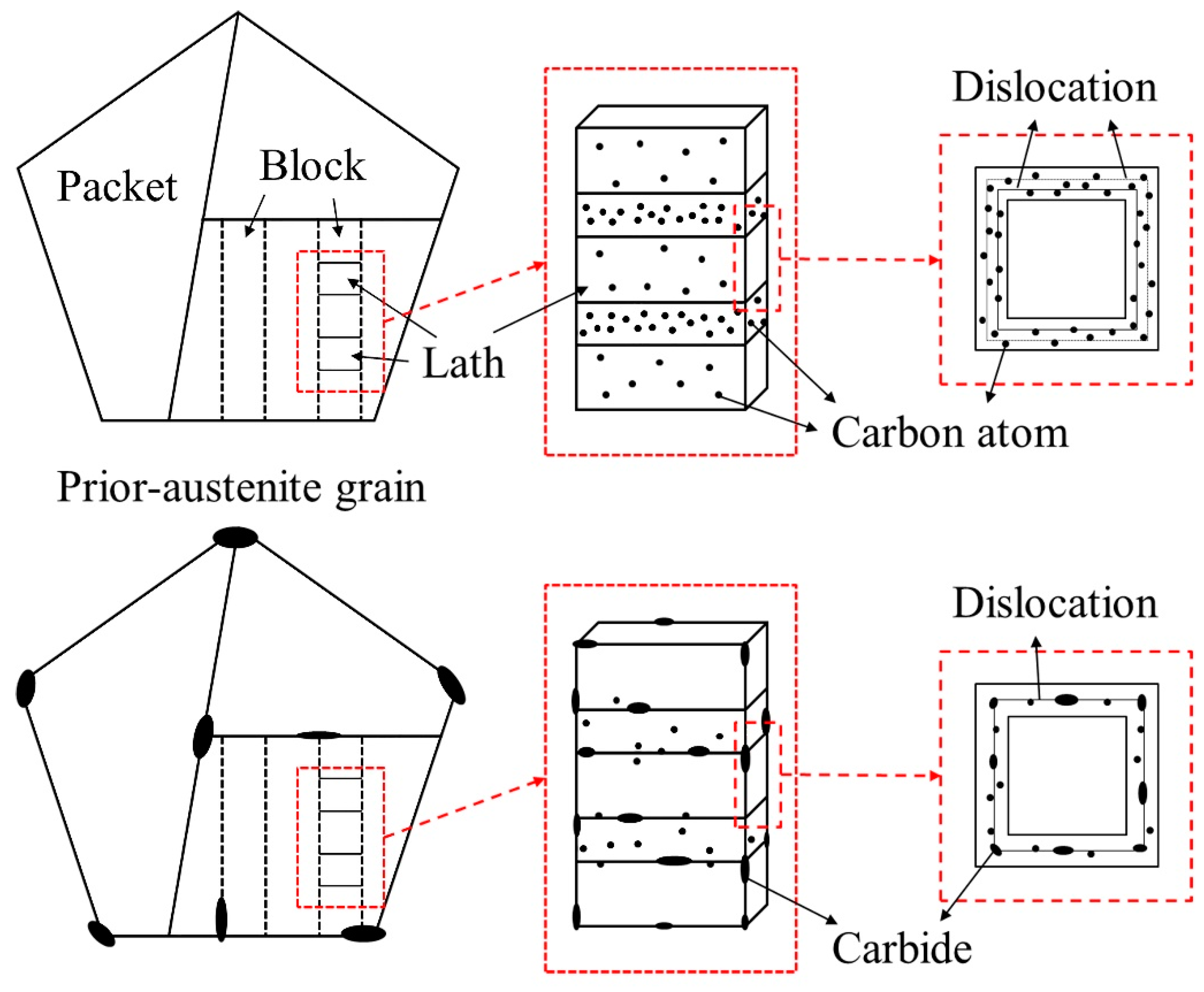
Figure 10 shows a schematic illustration of the evolution of the martensite hierarchical structures. During tempering, carbides precipitate and grow, while martensitic lath and dislocations recover. The main factors affecting the decrease in hardness of both steel alloys are martensite, carbides, and dislocations. Thus, the dislocation density of both steel alloys was calculated based on experimental data measured by X-ray diffraction, which is presented in the following section.

3.4. Dislocation Density

Martensite is a supersaturated solid solution of carbon in α-Fe, where the interstitial carbon atoms cause an asymmetric distortion of the lattice. The non-uniform stress field of the asymmetric distorted centers (carbon atoms) strongly interacts with the dislocations. Thus, the non-uniform stress field strongly hinders the movement of dislocations, resulting in the broadening of X-ray diffraction lines. Therefore, changes in the X-ray diffraction peaks can be used to characterize the dislocation densities of the alloys. The dislocation density ρ was calculated from the average microstrain values e according to [33]:
ρ = 14.4 e 2 b 2 ,
where b is the magnitude of the Burger’s vector ( b = 3 a / 2 for the bcc structure where a is the lattice parameter). The microstrain e can be calculated using the following Williamson–Hall equation [34]:
δ hkl cos θ hkl λ = 1 D + 4 e sin θ hkl λ ,
where θhkl is the diffraction angle, D is the mean size of the coherently diffracting domains, and λ is X-ray wavelength. In addition, δhkl was measured on a scale of 2θhkl and analyzed among four XRD peaks. The value of the microstrain e was obtained from a slop of a straight line, which could be generated by plotting δhklcosθhkl/λ vs. 4sinθhkl/λ.
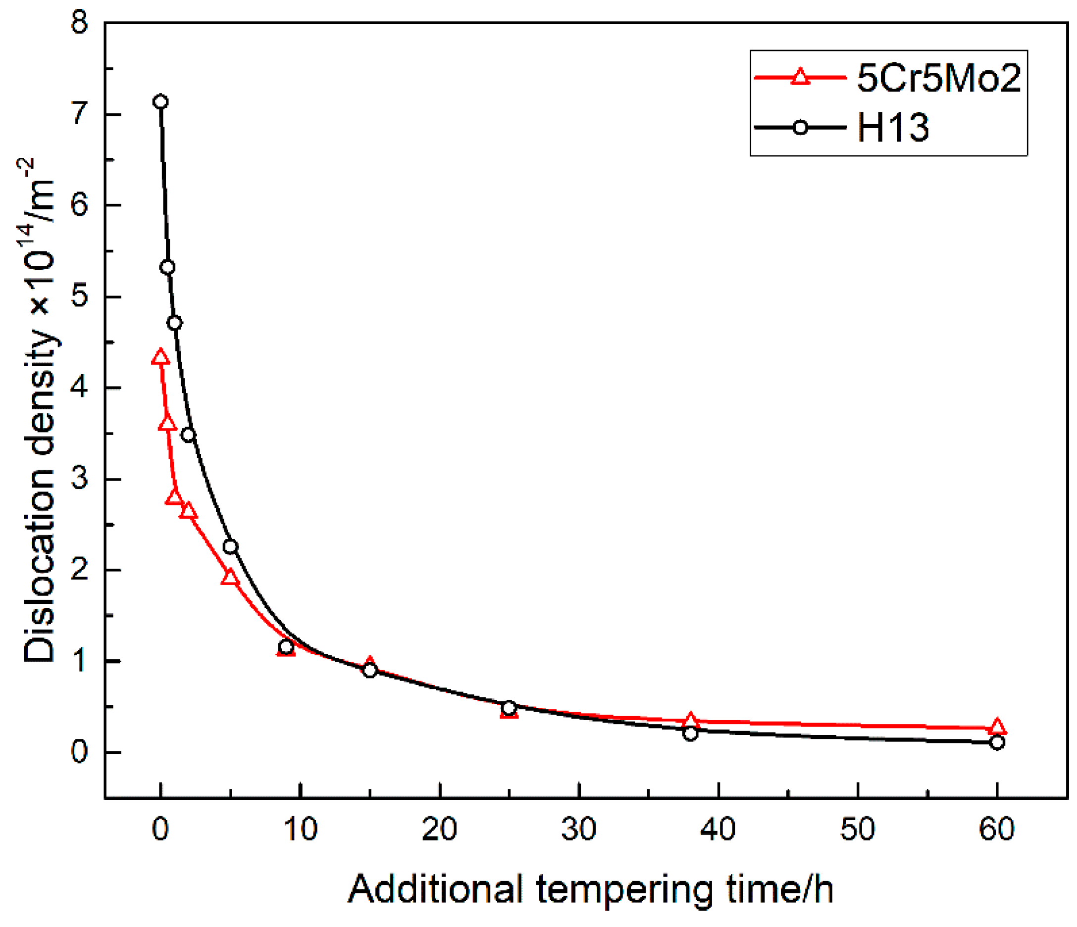
The dislocation density ρ can be calculated by Equation (1). The dislocation densities are plotted in Figure 11 as a function of the tempering duration. The dislocation density of the 5Cr5Mo2 specimens in their initial state (additional tempering for 0 h) is lower than that of the H13 steel. This is due to the different pre-heat-treatment processes used for the two steel alloys. The pre-heat-treatment temperatures of the 5Cr5Mo2 and H13 steel alloys were 600 °C and 580 °C, respectively. A higher tempering temperature results in a lower dislocation density. During the first 10 h of tempering, the dislocations recover, and the dislocation density sharply declines in both steel alloys. The subsequent decline is relatively slow. A schematic illustration of the dislocation changes after the tempering is also shown in Figure 10. The dislocation density of the 5Cr5Mo2 steel exceeds that of the H13 steel when both alloys are exposed to tempering exceeding 25 h. In general, the dislocation recovery rate of the 5Cr5Mo2 steel is lower than that of the H13 steel. This is because more fine precipitates along the lath boundaries and the lath result in more effective pinning dislocation slips.

3.5. Tempering Kinetics and the Softening Model

In the following section, a kinetic model is used to describe the solid transformation and recrystallization in the metallic materials. It is assumed that the solid-phase transformation is controlled by diffusion as proposed by Johnson and Mehl [35], and Avrami [36,37,38]. The model takes in the form of the Johnson–Mehl–Avrami equation as follows [7,39]:
τ = 1 exp ( D t n ) ,
where τ, t, and n are the tempering ratio, the heat preservation time of the temper, and the Avrami exponent, respectively. D could be determined according to the Arrhenius equation:
D = D 0 exp ( Q R T ) ,
where D0, Q, T and R are the pre-exponential constant, the activation energy of the tempering transformation, the tempering isothermal temperature in K, and the ideal gas constant (8.314 J·mol−l·K−1), respectively.
The following equation is used to describe the relationship between the tempering rate and the hardness [6]:
τ = H v H 0 H H 0 ,
where H0, H, and Hv are the hardness in the quenched state, the hardness in the annealed state, and the hardness after tempering a duration of v, respectively.
By inserting Equation (5) into Equation (3), the relationship between the tempering hardness Hv, D, and the tempering time t can be written as
lnln H 0 H H v H = n ln t + ln D .
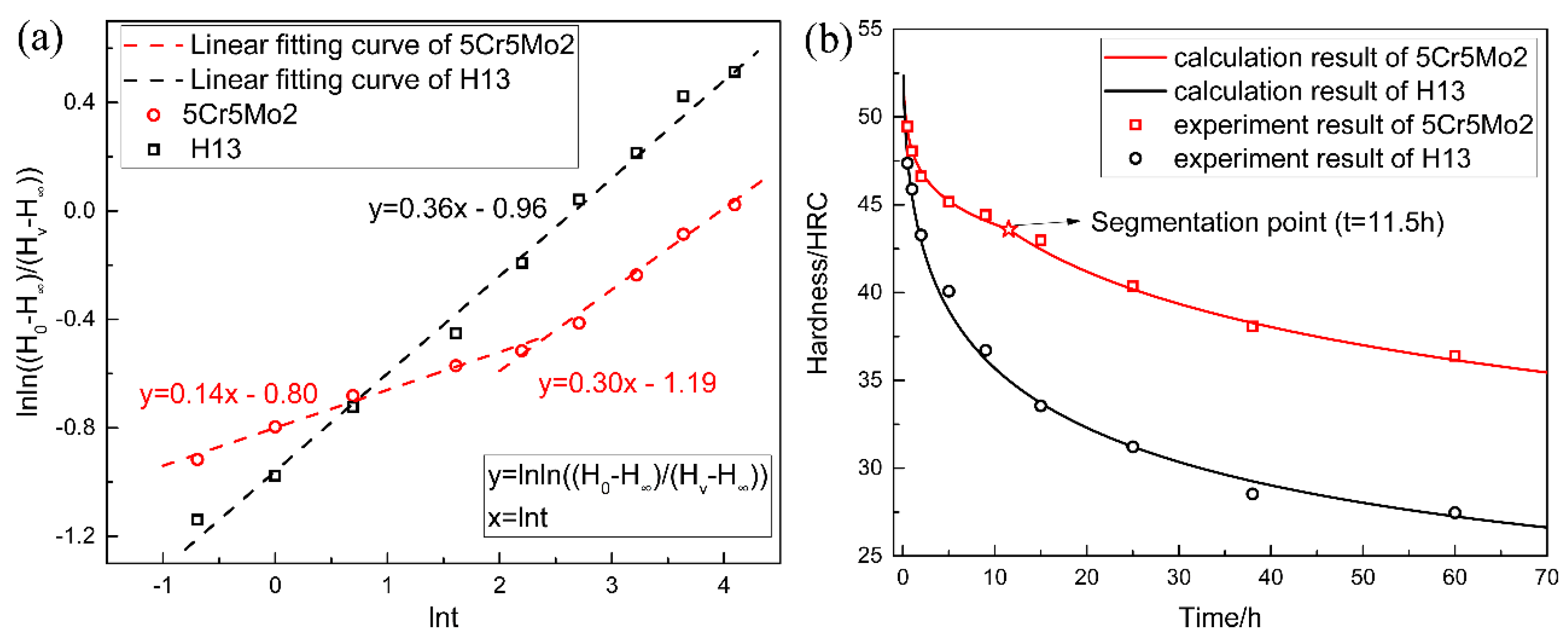
Using the hardness measurements of the two steel alloys tempered for various durations, the values of the Avrami exponent n and lnD can be obtained according to Equation (6). The data of lnln H 0 H H v H and ln t were plotted and fitted by linear curves (Figure 12a). It should be noted that, a single linear curve cannot fit the data of the 5Cr5Mo2 steel well. Hence, two linear curves with different slopes were used. The Avrami exponent n of the H13 steel tempered at 600 °C was 0.36. Conversely, the n values of the 5Cr5Mo2 steel during the first stage of the tempering (t < 11.5 h) were 0.14, and subsequently increased to 0.30 during the second stage (t > 11.5 h). The value of n describes the growth mechanism of the coarsening of large spheroids [7]. Therefore, the growth mechanism of the coarsening of large spheroids of the two steel alloys differs. Hence, it is speculated that this is caused by the presence of different types of carbides in the two steel alloys.
The values of lnD, which were obtained by extrapolating the curves to intersect the axis of ordinates, were −0.80 and −1.19 for the 5Cr5Mo2 steel and −0.96 for the H13 steel respectively. By transforming Equation (6), the tempering hardness can be expressed as
H v = H + ( H 0 H ) exp ( D t n ) .
Inserting n, lnD, H, and H0 into Equation (7), the softening equations of 5Cr5Mo2 and H13 can be obtained:
H v = { 21.3 + 42 exp ( e 0.80 t 0.14 ) , t < 11.5   h 21.3 + 42 exp ( e 1.19 t 0.30 ) , t > 11.5   h ,
H v = 20.3 + 37 exp ( e 0.96 t 0.36 ) .
The softening curves of the two steel alloys given by Equation (8) and Equation (9) are shown in Figure 12b. In addition, the measured hardness values are plotted in Figure 12b to verify the accuracy of the proposed equations. The calculated softening curves are generally consistent with the experimental results. Therefore, the softening equations can be used to predict the hardness of dies after prolonged usage at 600 °C.

4. Conclusions

In this study, a novel hot-work die steel of 5Cr5Mo2 with excellent thermal stability was designed. The mechanisms of the alloy’s superior thermal stability were elucidated by analyzing its hardness, microstructure, and tempering kinetics. The main observation and conclusion can be summarized as follows:
(1)
The designed steel exhibits a superior softening resistance as compared with the common H13 steel. After tempering for 60 h, the hardness of the 5Cr5Mo2 and H13 steels decreased from 49.8 HRC and 49.3 HRC to 36.4 HRC and 27.3 HRC, respectively.
(2)
The initial microstructure of the designed steel without the additional tempering primarily consisted of tempered martensite and fine alloy carbides. The typical secondary carbides in the 5Cr5Mo2 steel were elliptical vanadium carbides and fine acicular molybdenum carbides.
(3)
By the additional tempering, the smaller carbides were dissolved, and the coarsening of the selective carbide occurred. Martensites as well as dislocations were recovered in both steels. However, the initial characteristics of the martensite morphology were more pronounced in the 5Cr5Mo2 steel. Moreover, relatively finer carbides were retained in the 5Cr5Mo2 steel as compared to those in the H13 steel.
(4)
Initially, the dislocation density of the 5Cr5Mo2 steel was lower than that of the H13 steel due to its different pre-heat-treatment process. Nevertheless, after being exposed to an additional tempering lasting over 25 h, owing to the dislocation pinning by precipitation, the dislocation density exceeded that of the H13 steel.
(5)
By calculating the tempering kinetics of both steels, their softening equations were obtained and validated. The equations can be used to effectively predict the hardness of the dies after the prolonged service period at 600 °C.

Author Contributions

Conceptualization, N.D., Y.C. and H.L. (Hongwei Liu); methodology, N.D.; validation, N.D., Y.C. and H.L. (Hongwei Liu); formal analysis, N.D.; investigation, N.D., Y.C. and H.L. (Hongwei Liu); resources, H.L. (Hongwei Liu), P.F. and D.L.; data curation, N.D. and H.L. (Hongwei Liu); writing—original draft preparation, N.D.; writing—review and editing, N.D., Y.C., H.L. (Hongwei Liu), P.F., H.L. (Hanghang Liu) C.S.; visualization, N.D., Y.C. and H.L. (Hongwei Liu); supervision, D.L.; project administration, D.L.; funding acquisition, Y.C., H.L. (Hongwei Liu), P.F., H.L. (Hanghang Liu) and D.L. All authors have read and agreed to the published version of the manuscript.

Funding

This research was funded by National Natural Science Foundation of China (Grant No. 51701225), the Project to Strengthen Industrial Development at the Grass-roots Level (Grant No. TC190A4DA/35), Innovation project of the cutting-edge basic research and key technology by SYNL (Grant No. L2019R36), Young Talent Project by SYNL (Grant No. L2019F33) and China Postdoctoral Science Foundation (Grant No. 2019M661153).

Conflicts of Interest

The authors declare no conflict of interest.

References

  1. Medvedeva, A.; Bergström, J.; Gunnarsson, S.; Andersson, J. High-temperature properties and microstructural stability of hot-work tool steels. Mater. Sci. Eng. A 2009, 523, 39–46. [Google Scholar] [CrossRef]
  2. Roberts, G.; Krauss, G.; Kennedy, R. Tool Steels, 5th ed.; ASM International: Novelty, OH, USA, 1998. [Google Scholar]
  3. Jilg, A.; Seifert, T. Temperature dependent cyclic mechanical properties of a hot work steel after time and temperature dependent softening. Mater. Sci. Eng. A 2018, 721, 96–102. [Google Scholar] [CrossRef]
  4. Chander, S.; Chawla, V. Failure of hot forging dies—An updated perspective. Mater. Today Proc. 2017, 4, 1147–1157. [Google Scholar] [CrossRef]
  5. Pešička, J.; Kužel, R.; Dronhofer, A.; Eggeler, G. The evolution of dislocation density during heat treatment and creep of tempered martensite ferritic steels. Acta Mater. 2003, 51, 4847–4862. [Google Scholar] [CrossRef]
  6. Zhang, Z.; Delagnes, D.; Bernhart, G. Microstructure evolution of hot-work tool steels during tempering and definition of a kinetic law based on hardness measurements. Mater. Sci. Eng. A 2004, 380, 222–230. [Google Scholar] [CrossRef] [Green Version]
  7. Zhou, Q.; Wu, X.; Shi, N.; Li, J.; Min, N. Microstructure evolution and kinetic analysis of DM hot-work die steels during tempering. Mater. Sci. Eng. A 2011, 528, 5696–5700. [Google Scholar] [CrossRef]
  8. Hu, X.; Li, L.; Wu, X.; Zhang, M. Coarsening behavior of M23C6 carbides after ageing or thermal fatigue in AISI H13 steel with niobium. Int. J. Fatigue 2006, 28, 175–182. [Google Scholar] [CrossRef]
  9. Zhu, J.; Zhang, Z.; Xie, J. Improving strength and ductility of H13 die steel by pre-tempering treatment and its mechanism. Mater. Sci. Eng. A 2019, 752, 101–114. [Google Scholar] [CrossRef]
  10. Malheiros, L.R.C.; Rodriguez, E.A.P.; Arlazarov, A. Mechanical behavior of tempered martensite: Characterization and modeling. Mater. Sci. Eng. A 2017, 706, 38–47. [Google Scholar] [CrossRef]
  11. Michaud, P.; Delagnes, D.; Lamesle, P.; Mathon, M.H.; Levaillant, C. The effect of the addition of alloying elements on carbide precipitation and mechanical properties in 5% chromium martensitic steels. Acta Mater. 2007, 55, 4877–4889. [Google Scholar] [CrossRef] [Green Version]
  12. Delagnes, D.; Lamesle, P.; Mathon, M.H.; Mebarki, N.; Levaillant, C. Influence of silicon content on the precipitation of secondary carbides and fatigue properties of a 5%Cr tempered martensitic steel. Mater. Sci. Eng. A 2005, 394, 435–444. [Google Scholar] [CrossRef] [Green Version]
  13. Saha, D.C.; Biro, E.; Gerlich, A.P.; Zhou, Y. Effects of tempering mode on the structural changes of martensite. Mater. Sci. Eng. A 2016, 673, 467–475. [Google Scholar] [CrossRef]
  14. Gomes, C.; Kaiser, A.-L.; Bas, J.-P.; Aissaoui, A.; Piette, M. Predicting the mechanical properties of a quenched and tempered steel thanks to a “tempering parameter”. Rev. Metall. 2010, 107, 293–302. [Google Scholar] [CrossRef]
  15. Revilla, C.; López, B.; Rodriguez-Ibabe, J.M. Carbide size refinement by controlling the heating rate during induction tempering in a low alloy steel. Mater. Des. 2014, 62, 296–304. [Google Scholar] [CrossRef]
  16. Furuhara, T.; Kobayashi, K.; Maki, T. Control of cementite precipitation in lath martensite by rapid heating and tempering. ISIJ Int. 2004, 44, 1937–1944. [Google Scholar] [CrossRef]
  17. Hernandez, V.H.B.; Nayak, S.S.; Zhou, Y. Tempering of martensite in dual-phase steels and its effects on softening behavior. Metall. Mater. Trans. A 2011, 42, 3115–3129. [Google Scholar] [CrossRef]
  18. Nayak, S.S.; Hernandez, V.H.B.; Zhou, Y. Effect of chemistry on nonisothermal tempering and softening of dual-phase steels. Metall. Mater. Trans. A 2011, 42, 3242–3248. [Google Scholar] [CrossRef]
  19. Bhadeshia, H.; Honeycombe, R. Tempering of Martensite. In Steels: Microstructure and Properties, 4th ed.; Gifford, C., Ed.; Butterworth-Heinemann: Oxford, UK, 2017; pp. 237–270. [Google Scholar]
  20. Mote, V.D.; Purushotham, Y.; Dole, B.N. Williamson-Hall analysis in estimation of lattice strain in nanometer-sized ZnO particles. J. Theoret. Appl. Phys. 2012, 6, 6. [Google Scholar] [CrossRef] [Green Version]
  21. Dini, G.; Ueji, R.; Najafizadeh, A.; Monir-Vaghefi, S.M. Flow stress analysis of TWIP steel via the XRD measurement of dislocation density. Mater. Sci. Eng. A 2010, 527, 2759–2763. [Google Scholar] [CrossRef]
  22. Dragomir, I.C.; Li, D.S.; Castello-Branco, G.A.; Garmestani, H.; Snyder, R.L.; Ribarik, G.; Ungar, T. Evolution of dislocation density and character in hot rolled titanium determined by X-ray diffraction. Mater. Charact. 2005, 55, 66–74. [Google Scholar] [CrossRef]
  23. ABaghdadi, H.; Rajabi, A.; Selamat, N.F.M.; Sajuri, Z.; Omar, M.Z. Effect of post-weld heat treatment on mechanical behavior and dislocation density of friction stir welded Al6061. Mater. Sci. Eng. A 2019, 754, 728–734. [Google Scholar] [CrossRef]
  24. Liu, H.; Fu, P.; Liu, H.; Sun, C.; Sun, M.; Li, D. A novel large cross-section quenching and tempering mold steel matching excellent strength–hardness–toughness properties. Mater. Sci. Eng. A 2018, 737, 274–285. [Google Scholar] [CrossRef]
  25. Chen, Y.-W.; Huang, B.-M.; Tsai, Y.-T.; Tsai, S.-P.; Chen, C.-Y.; Yang, J.-R. Microstructural evolutions of low carbon Nb/Mo-containing bainitic steels during high-temperature tempering. Mater. Charact. 2017, 131, 298–305. [Google Scholar] [CrossRef]
  26. Jang, J.H.; Lee, C.-H.; Heo, Y.-U.; Suh, D.-W. Stability of (Ti, M)C (M= Nb, V, Mo and W) carbide in steels using first-principles calculations. Acta Mater. 2012, 60, 208–217. [Google Scholar] [CrossRef]
  27. Wang, Z.; Zhang, H.; Guo, C.; Liu, W.; Yang, Z.; Sun, X.; Zhang, Z.; Jiang, F. Effect of molybdenum addition on the precipitation of carbides in the austenite matrix of titanium micro-alloyed steels. J. Mater. Sci. 2016, 51, 4996–5007. [Google Scholar] [CrossRef]
  28. Chen, C.Y.; Yen, H.W.; Kao, F.H.; Li, W.C.; Huang, C.Y.; Yang, J.R.; Wang, S.H. Precipitation hardening of high-strength low-alloy steels by nanometer-sized carbides. Mater. Sci. Eng. A 2009, 499, 162–166. [Google Scholar] [CrossRef]
  29. Krajnik, P.; Kopač, J. Modern machining of die and mold tools. J. Mater. Process. Technol. 2004, 157–158, 543–552. [Google Scholar] [CrossRef]
  30. Bhadeshia, H.; Honeycombe, R. Formation of Martensite, in Steels: Microstructure and Properties, 4th ed.; Gifford, C., Ed.; Butterworth-Heinemann: Oxford, UK, 2017; pp. 135–177. [Google Scholar]
  31. Sakamoto, H.; Otsuka, K.; Shimizu, K. Rubber-like behavior in a Cu-Al-Ni alloy. Scr. Metall. 1977, 11, 607–611. [Google Scholar] [CrossRef]
  32. Kwon, H.; Lee, K.B.; Yang, H.R.; Lee, J.B.; Kim, Y.S. Secondary hardening and fracture behavior in alloy steels containing Mo, W, and Cr. Metall. Mater. Trans. A 1997, 28, 775–784. [Google Scholar] [CrossRef]
  33. Williamson, G.K.; Smallman, R.E., III. Dislocation densities in some annealed and cold-worked metals from measurements on the X-ray debye-scherrer spectrum. Philos. Mag. 1956, 1, 34–46. [Google Scholar] [CrossRef]
  34. Williamson, G.K.; Hall, W.H. X-ray line broadening from filed aluminum and wolfram. Acta Metall. 1953, 1, 22–31. [Google Scholar] [CrossRef]
  35. Johnson, W.A.; Mehl, R.F. Reaction kinetics in processes of nucleation and growth. Trans. Am. Inst. Min. Met. Eng. 1939, 135, 416–442. [Google Scholar]
  36. Avrami, M. Kinetics of phase change I. J. Chem. Phys. 1939, 7, 1103–1112. [Google Scholar] [CrossRef]
  37. Avrami, M. Kinetics of phase change II. J. Chem. Phys. 1940, 8, 212–224. [Google Scholar] [CrossRef]
  38. Avrami, M. Granulation, Phase change, and microstructure kinetics of phase change III. J. Chem. Phys. 1941, 9, 177–184. [Google Scholar] [CrossRef]
  39. Watté, P.; van Humbeeck, J.; Aernoudt, E.; Lefever, I. Strain ageing in heavily drawn eutectoid steel wires. Scripta Mater. 1996, 34, 89–95. [Google Scholar] [CrossRef]
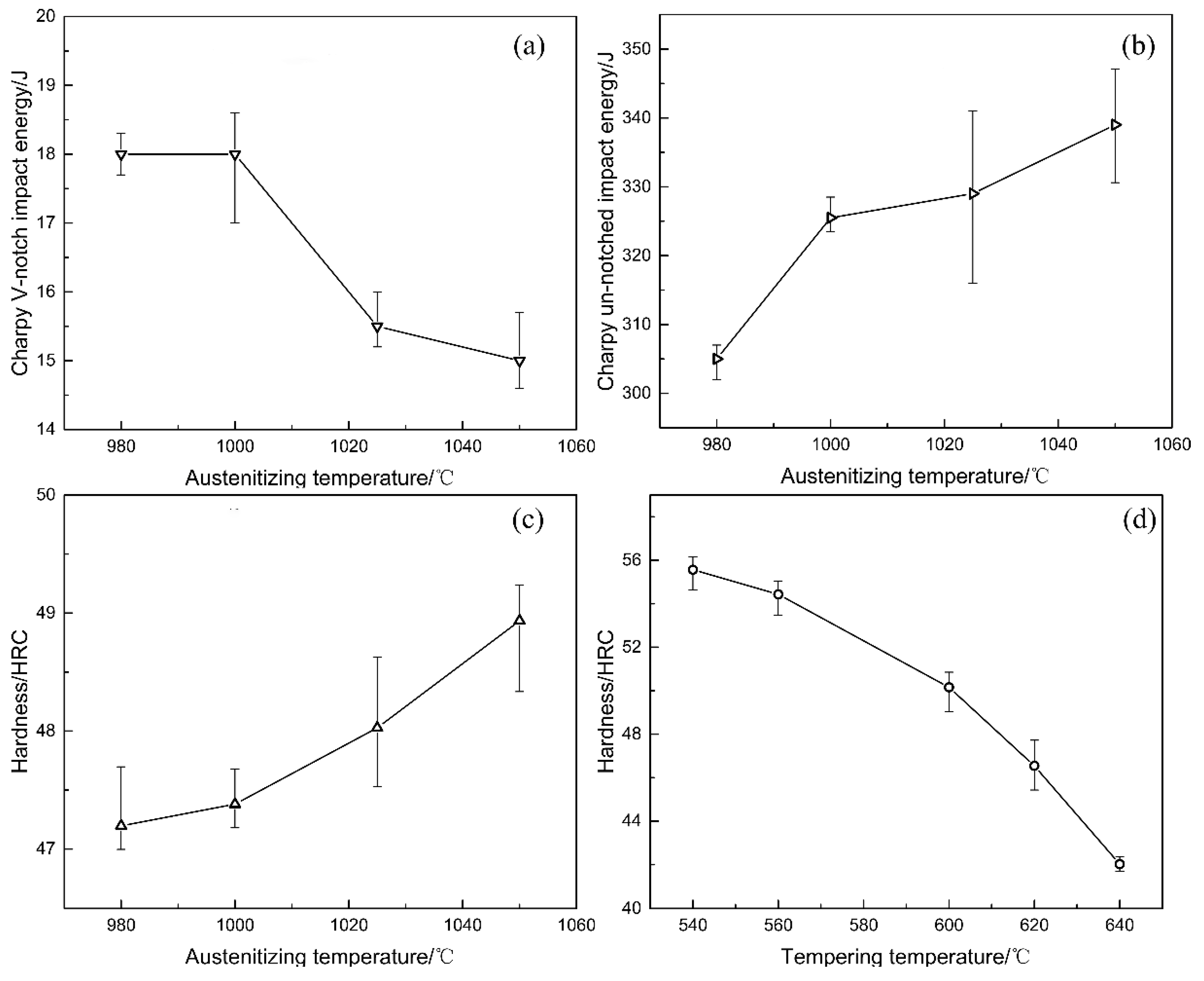
Figure 1. The effect of different austenitizing temperatures on (a) Charpy V–notch impact energy; (b) Charpy un-notched impact energy and (c) hardness; and (d) hardness value as a function of the tempering temperatures of the 5Cr5Mo2 steel with an austenitizing temperatures of 1050 °C.
Crystals 10 00238 g001
Figure 2. The pre-heat-treatment process of (a) 5Cr5Mo2 steel and (b) H13 steel; (c) The additional tempering process.
Crystals 10 00238 g002
Figure 3. Results of the thermodynamic calculation of the equilibrium precipitation phases of the (a) 5Cr5Mo2 steel; and (b) H13 steel.
Crystals 10 00238 g003
Figure 4. Equilibrium composition of the (a) MC, (b) M2C, and (c) M23C6 phases in the 5Cr5Mo2 steel and (d) MC, (e) M6C, (f) M23C6 phase in the H13 steel.
Crystals 10 00238 g004
Figure 5. Hardness of the 5Cr5Mo2 and H13 steel alloys as functions of the tempering duration.
Crystals 10 00238 g005
Figure 6. Microstructure and hardness after a tempering lasting (a) 0 h, (b) 25 h, and (c) 60 h for the 5Cr5Mo2 steel; and (d) 0 h, (e) 25 h, (f) 60 h for the H13 steel.
Crystals 10 00238 g006
Figure 7. Microstructure of both steel alloys prior to additional tempering: (a) microstructure of the 5Cr5Mo2 steel observed by SEM; (b) elliptical-shaped secondary carbides and (c) fine needle-shaped secondary carbides of the 5Cr5Mo2 steel observed by TEM; (d) microstructure of the H13 steel observed by SEM; (e) secondary carbides and (f) large-size primary carbides of the H13 steel observed by TEM; (g) morphology, (h) diffraction, and (i) energy spectra of particle A.
Crystals 10 00238 g007
Figure 8. X-ray diffraction (XRD) patterns of the carbide powder extracted from the 5Cr5Mo2 and H13 steels.
Crystals 10 00238 g008
Figure 9. Microstructure of both steel alloys after tempering for 60 h: (a) microstructure of the 5Cr5Mo2 steel observed by SEM; (b) elliptical-shaped secondary carbides and (c) bar-like secondary carbides in the 5Cr5Mo2 steel observed by TEM; (d) microstructure of the H13 steel observed by SEM; (e) large-size and (f) fine secondary carbides in the H13 steel observed by TEM; (g) diffraction and (h) energy spectra of particle B; (i) diffraction and (j) energy spectra of particle C.
Crystals 10 00238 g009
Figure 10. Schematic illustration of the evolution of martensite, carbides, and dislocations after a long-lasting tempering.
Crystals 10 00238 g010
Figure 11. Dislocation density as a function of the tempering duration.
Crystals 10 00238 g011
Figure 12. (a) Determination of the Avrami exponent n and lnD using curve fitting. (b) Softening curves and experimental hardness results of the 5Cr5Mo2 and H13 steel alloys.
Crystals 10 00238 g012
Table 1. Measured chemical composition of two alloys, in wt%, balance Fe.
SteelCCrMoVSiMn
5Cr5Mo20.505.142.480.510.200.50
H130.325.051.350.900.970.32