Article

Response Improvement of Liquid Crystal-Loaded NRD Waveguide Type Terahertz Variable Phase Shifter

Department of Electrical and Electronic Engineering, National Defense Academy, Yokosuka, Kanagawa 239-8686, Japan
*
Author to whom correspondence should be addressed.
Crystals 2020, 10(4), 307; https://doi.org/10.3390/cryst10040307
Submission received: 31 March 2020 / Revised: 13 April 2020 / Accepted: 14 April 2020 / Published: 16 April 2020
(This article belongs to the Special Issue Microwave Liquid Crystal Technology)

Abstract

:
Liquid crystals, which have high dielectric anisotropy even in the terahertz region and are easily controllable for dielectric permittivity by applying an electric field, have become increasingly attractive in recent years. The non-radiative dielectric (NRD) waveguide has a structure in which a dielectric line is sandwiched between two metal plates and by replacing the dielectric part with liquid crystal, a low loss liquid crystal-loaded NRD waveguide type terahertz phase shifter can be obtained. However, since the thickness of the liquid crystal layer is several hundred micrometers, it has a response time of as long as several hundred seconds when the driving voltage is removed. It is necessary to devise improvements for practical application. By inserting two polyethylene terephthalate (PET) films and reducing the thickness of the liquid crystal layer, the decay time was improved well, but the phase change was significantly reduced. In this study, we report improving both decay time and phase change with aligned nanofiber/liquid crystal complex. In addition, we demonstrate liquid crystal-load phase shifter, which has 360° phase change and the response time below one second.

1. Introduction

The speed of wireless transmission has been progressing, and the demand for large capacity and high-speed connection has increased. The frequency band used for communication has been growing gradually, and in recent years, terahertz waves have received attention as a new frequency region. Terahertz waves, which are higher in frequency than microwaves and millimeter waves, and have a wide frequency bandwidth from 100 GHz to 10 THz, can be used for communications to increase the speed of wireless communications. However, it is tough to develop technology to generate and detect terahertz waves because they are located between radio waves and light waves. Transmission loss is enormous in printed circuit boards that behave as transmission lines, such as microstrip lines and coplanar lines, which have been proven to be efficient in the microwave and millimeter wave region [1]. As mentioned, there are barriers to the development of terahertz waves. To realize wireless communication technology using terahertz waves, it is necessary to develop a terahertz wave control elements with low loss characteristics.
Furthermore, with the advancement of satellites and mobiles, it is necessary to clear various requirements in the development of multi-directional communication technology. In general, an antenna mounted on a mobile object should be small, lightweight, high gain, and capable of controlling transmission and reception directions. Among them, there is a phased array antenna that arranges multiple antennas and combines the outputs from them to not only control the gain but also control the direction of the wave beam. By adjusting the phase of the variable phase shifters in this structure, the direction of the beam becomes controllable, and one antenna can receive from the multiple directions or transmit to the multiple directions. In recent years, with the development of satellite communication, a high-performance high-frequency band variable phase shifter is becoming increasingly required. The expected characteristics are electrical drive, full phase shift band of 0–360°, low losses, and fast response time that must meet a minimum requirement of one second or less for static devices.
On the other hand, owing to unique electro-optical properties and optical properties, liquid crystals (LCs) are known to be widely used not only in optical applications, such as displays, lasers, or optical modulators, but also in various fields [2,3,4,5]. In recent years, LCs have attracted attention as one of the high-frequency materials in which transmission characteristics can be changed by controlling and adjusting permittivity [6,7]. Nematic LCs (NLCs) have high dielectric anisotropy, which also exists in the terahertz wave region. Because of their low level of orientation order, NLCs have low viscosity and good responsiveness to an electric field. Since their alignment can be easily controlled by an external electric field, a phase shifter that enables variable phase change, high-speed response, and electrical drive can be realized by using NLCs.
In previous research, we had succeeded in realizing a LC-loaded non-radiative dielectric (NRD) guide type terahertz phase shifter with low loss and large phase change. However, since the thickness of the LC layer of the phase shifter is several hundred micrometers, the decay time when removing the voltage is as long as several hundred seconds, which is serious problem in application. By inserting two polyethylene terephthalate (PET) films and reducing the thickness of the LC layer, the decay time was improved and a variable phase change was obtained. However, the amount of phase change was significantly reduced [8]. In this study, we report the improvement of decay time by using aligned nanofiber (NF)/LC complex. Furthermore, the liquid crystal-load phase shifter, which has 360° phase change and the response time below one second, is demonstrated.

2. LC loaded NRD Waveguide Type Terahertz Phase Shifter

2.1. NRD Waveguide

2.1.1. Basic Structure and Operation

The structure of the NRD waveguide, according to the research of T. Yoneyama in 1988, simply consists of dielectric strip sandwiched between two metal plates [9]. The distance between two metal plates takes a value between a half wavelength in the dielectric and a half wavelength in the air. The electromagnetic wave only exists between the plates if the distance d between the metal plates is more than the half-wavelength λ/2 of the propagated electromagnetic wave due to the effect of the cut off wavelength of the parallel plate mode. Since the dielectric has a higher dielectric constant than air, the wavelength of the electromagnetic wave transmitted in the dielectric is shorter than the wavelength in air. By sandwiching the dielectric between the metal plates, it becomes possible to create two parts where the electromagnetic wave can exist and cannot exist. Here, since the distance d between the metal plates of the NRD waveguide is between the half wavelength in the dielectric and the half wavelength in the air, the electromagnetic wave is cut off in the air region and propagates only in the dielectric region. This is the operating principle of the NRD waveguide. When the relative dielectric constant of the dielectric strip is εr = 3.1 and the frequency of the transmitted electromagnetic wave is f = 350 GHz, d must be 243 to 428 µm.

2.1.2. NRD Waveguide Operation by Simulation

By creating a part where electromagnetic waves can and cannot exist, the NRD waveguide has characteristics such as low loss and restriction of undesired radiation at curved sections and discontinuities. Until now, the main frequency band used in the NRD waveguide is the 60 GHz band [10,11], but the operating principle works regardless of the frequency band. We will perform a simulation by using the CST STUDIO SUITE software, which is a 3D electromagnetic field analysis software developed by AET, Inc. The purpose is to check the propagation characteristics of the NRD guide in the terahertz region. A model, as shown in Figure 1, was made, and used to confirm whether it would function as an NRD guide when a plane wave propagated along the Y-axis of this model. Here, the dielectric part is a rectangular parallelepiped having a width of 2 mm, a length of 5 mm, and a thickness of 250 µm. The dielectric constant is 3.1. Looking at the simulation result at 350 GHz shown in Figure 2, the electric field distribution in the airside region away from the dielectric region is displayed in blue. When the increase in electric field strength is shown in order from blue to red, it means that the electric field strength is zero. Furthermore, near the boundary between the dielectric portion and the air portion, the electric field is extremely weak and can be regarded as non-existent. Since almost no electromagnetic wave leaked from the dielectric part to the air part, the effect of cutoff wavelength and non-radiation were confirmed. From the color shown in the enlarged view of Figure 2c,d, it can be confirmed that the electric field in the central portion is the strongest, the electric field decreases as approaching the metal plate, and the electric field near the metal plate becomes almost zero. Similarly, the direction of the electric field is parallel to the metal substrate without radiation. Based on the above results, we can understand that the electromagnetic wave was confined in the structure of the NRD waveguide.

2.2. LC loaded NRD Waveguide Type Terahertz Phase Shifter

2.2.1. Phase Change Mechanism of Terahertz Wave by the Liquid Crystal

LCs have dielectric anisotropy, which also exists in the terahertz wave region. The refractive index along the long axis direction of the LC molecules is the extraordinary refractive index n e , the refractive index along the short axis direction is the ordinary refractive index n o , and the angle between the direction of the LC molecules and the electric field direction of the terahertz wave is θ   ( 0 ° θ 90 ° ) . At this time, the refractive index changes depending on the angle θ . The relationship is shown in the following Equation (1) [12].
n ( θ ) = n 0 · n e n 0 2 · c o s 2 θ + n e 2 · s i n 2 θ
When no voltage is applied, that is θ = 0°, the refractive index felt by the terahertz wave is the extraordinary refractive index n e . When an electric field is applied to the LC molecules, the orientation direction of the molecules changes in the direction of the electric field so that θ can be changed. Since the refractive index felt by the terahertz wave changes from the extraordinary refractive index n e to the refractive index n ( θ ) , the phase of the terahertz wave transmitted through the LC before and after the application of the electric field changes. The phase change can be expressed by the following Equation (2).
Δ φ = 2 π f l c ( n e n ( θ ) )
Δ φ m a x = 2 π f l c Δ n
here, ∆φ, f, l, c, and ∆n are the phase change amount, the frequency of the terahertz wave, the length of the NRD waveguide, the speed of light, and the birefringence of the LC material, respectively. This is the phase-change mechanism of a LC-loaded NRD waveguided terahertz phase shifter. From the Equation (2), a large amount of phase change ∆φ can be obtained by increasing the length l or using a LC material with high ∆n.

2.2.2. Structure of the Device

The LC is used instead of the solid dielectric part of the original NRD waveguide. Moreover, if the size is too large, it will be difficult to carry out the rubbing process, so we propose a structure that divides the device into two parts, a LC cell and metal plates. Figure 3 shows the structures of LC loaded NRD waveguided terahertz phase shifter with the pure LC or aligned nanofiber/LC complex.
Since the rubbing process was performed with the direction in the initial alignment state of the LC molecules and the direction of the electric field of the terahertz wave, the average tilt angle of the LC molecules in the cell was equal to the angle between the director and the electric field direction of the terahertz wave. In this study, the spacing between the metal plates of the device is 250 µm, and the length of the propagation line is 5 mm. For the drive voltage supply, since the voltage is applied directly to the metal plates, the direction of the electric field is from the upper plate to the lower plate.

3. Improvement Principle

The decay time τ d when the voltage of the NLC is removed can be expressed by Equation (3) [12].
τ d = η · d 2 K · π 2
here, η is the viscosity, and Κ is the elastic constant. From Equation (3), the decay time when the applied voltage is removed depends only on the thickness d of the LC layer. As the decay time significantly increases according to the quadratic dependence on the thickness of LC layer, many blends and composites with LC have been studied to shorten it such as polymer dispersed LCs (PDLCs) [13,14,15,16,17], polymer-stabilized NLCs with thermal polymerization [18,19], and UV polymerization [20,21], and the composite of aligned NF from electrospinning and LC [22]. Due to opaque metal plates in the structure of the NRD guide, it is difficult to form a polymer network by ultraviolet irradiation. On the other hand, NFs, which are polymer fibers with diameters from a few nanometers to 1 µm, are widely used from biomedical fields [23,24,25,26,27,28] to energy-related devices [29,30,31,32,33,34] and are attracting attention in the application of electronic devices. Since the NF has a minimal diameter, interaction with LC molecules is expected.
Figure 4 shows a conceptual diagram of an aligned nanofiber/liquid crystal complex (NF/LC). Within the composite structure, each NF acts as an interface, like an alignment layer. Since the LC molecules in contact with the NFs receive the alignment regulating force, the LC layer thickness can be substantially regarded as the interval between the NFs and the similar effect as when reducing the LC layer thickness is obtained. The decay time of the NF/LC is proportional to the square of the distance between NFs in composite structure but not to the entire LC layer thickness. When the LC is injected into a cell containing NFs, it is possible to reduce the distance between interfaces while maintaining the entire LC layer thickness. Therefore, a large phase change and a short decay time can be expected. Moreover, since the diameter of the nanofiber is smaller than the wavelength of the terahertz wave or light, the nanofiber has an average refractive index of fiber and air, so optically diffused reflection is reduced and no reflection occurs at the nanofiber-air interface. Due to this feature, it is considered that introducing nanofibers into the liquid crystal layer does not cause an increase in transmission loss.
We used polyacrylonitrile (PAN) as a polymer material to form NFs. In this study, NF was fabricated by using electrospinning equipment (MECC, NANON-03), as shown in Figure 5. First, the PAN was mixed with solvent solution dimethylformamide (DMF), and dissolved before being heated to about 60 °C for six hours by a heating device (ASONE, RSH-4DN) to make a PAN polymer solution with a concentration of 12 wt%. Then, the polymer solution was injected into a metal nozzle with a syringe and pumped out with a feed rate of 1 mL/h. A collector electrode is arranged thereunder, while a high voltage of 20 kV is applied therebetween. The applied electric force between the metal nozzle and the collector exceeds the surface tension of the droplet of the polymer solution, and a polymer liquid jets are released from the metal nozzle tip toward the grounded collector. The liquid jet continuously elongates, while the solvent in the liquid jet gradually evaporates during the process. The jet size reduces to nano size when reaching the collector, and NF is obtained. One thing to note here is that with the stationary collector, randomly aligned NFs are collected. The collector which we used in this equipment is a rotatable drum, and by rotating the drum at a high-speed of 1200 rpm, the formed nanofibers are given an initial orientation along the rotating direction of the collector.

4. Measurement System

4.1. Permittivity Measurement System

Figure 6 shows a system for measuring the driving voltage dependence of the permittivity.
We generated a measurement voltage (10 mVpp) with a frequency of 10 kHz and a LC driving voltage with a frequency of 1 kHz from a multifunction generator (NF, WF1968), amplified them 40 times with a power amplifier (NF, HSA4051) before applying to the indium tin oxide (ITO) glass parallel cells (LC cells) introduced in the previous study [8]. The amplitude and phase of the voltage of the resistor connected in series with the LC cell are detected by the radio frequency (RF) lock-in amplifier (NF, LI5655), and the complex permittivity of the LC can be obtained. According to that result, we can also find the relationship between the driving voltage and the permittivity of LC materials and measure their response time. To measure the relationship between the driving voltage and the permittivity of LC material, the cells were submitted to a modulated triangular signal whose amplitude varies 0 to 100 Vrms over 200 seconds. For response time measurement, the generator provided a sine wave of triggered burst, which was amplified by the amplifier before being applied to the LC cells having a thickness of 25 µm. We successively measured the rise time and the decay time for an input voltage from 5 V to 25 V in 5 V steps. The voltage was maintained for four seconds to ensure that the LC molecules move to their final position.

4.2. Terahertz Wave Measurement System

In the experiment, a terahertz wave is generated by multiplying a microwave by 36 times in a frequency extender (Extender WR2.2, Virginia Diodes, Inc, Charlottesville, VA, USA). The terahertz waves are radiated into the air by the transmitting horn antenna and passed through the phase shifter before reception by the receiving horn antenna. By comparing the reference signal (or incident signal) with the signal after reception, the network analyzer (N5222B, Keysight, Santa Rosa, CA, USA) calculated the intensity and phase of the transmission characteristic S21 and visualized on an internal oscilloscope. The response time can be received from the observation result of the phase of S21. Figure 7 shows block diagram of the terahertz wave measurement system. As for the driving voltage supply, a sine wave of triggered burst or a sine wave modulated with a square wave, after being generated from a function generator (WF1947, NF, Yokohama, Japan) and amplified 200 times by a power amplifier (HJOPS-1B10, Matsusada Precision, Shiga-ken, Japan), was applied to upper and lower metal plates. In this experiment, the driving voltage magnitude was applied from 20 Vrms up to the maximum of 180 Vrms.

5. Improvement

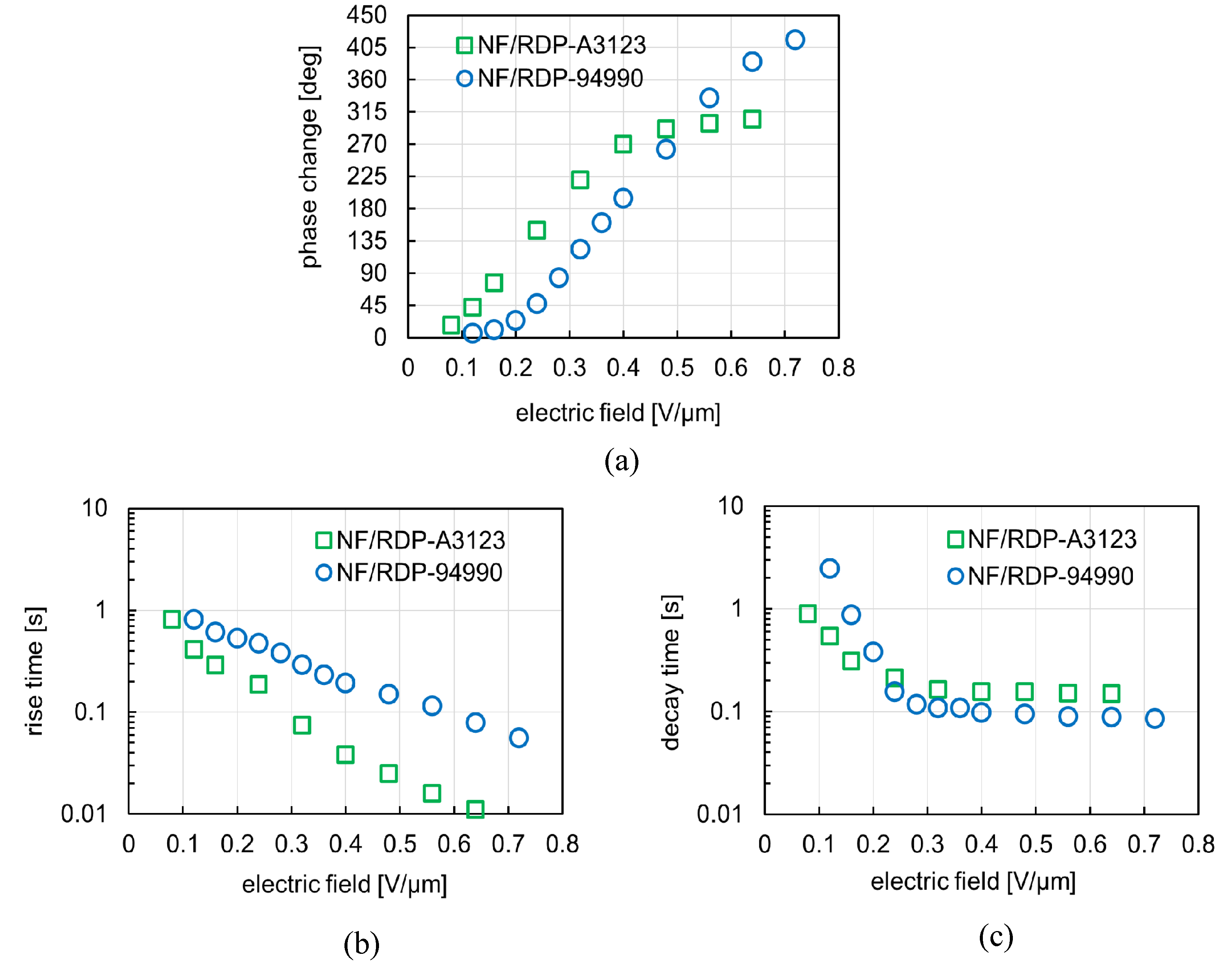
5.1. Two NLCs of RDP-A3123 and RDP-94990

In previous research, an NRD waveguide terahertz phase shifter loaded with a pure NLC 5CB with a LC layer thickness of 350 µm was presented [8]. Although it had a large phase change of about 314°, the decay time was very long at 292 s, which makes it impossible for practical applications. In this study, the thickness of the LC layer is first reduced to 250 µm. Then, two types of NLC made by DIC Corporation, RDP-A3123 and RDP-94990 are used for improvement. Table 1 shows phase transition temperatures and viscosities of three LC materials of 5CB, RDP-A3123, and RDP-94990.
Furthermore, the NLCs RDP-A3123 and RDP-94990 have larger birefringence than the NLC 5CB. The refractive indexes, birefringences, and absorbances of three LC materials are shown in Figure 8. In this study, the terahertz spectroscopic imaging system (Advantest, TAS7500) was used with a quartz glass cell whose cell gap is one millimeter.
At 350 GHz, the birefringence of 5CB, RDP-A3123, and RDP-94990 are about 0.150, 0.180, and 0.215, respectively. When the waveguide length of the phase shifter is 5 mm, and the frequency of the terahertz wave is 350 GHz, the maximum phase change of 5CB can be calculated by using Equation (2).
Δ φ m a x ( 5 CB ) = 2 × 180 × 350 × 10 9 × 5 × 10 3 3 × 10 8 × 0.15 = 315 °
When similarly calculated, the maximum phase change of RDP-A3123 and RDP-94990 are approximately 378° and 450°, respectively.
In this study, we use the absorbance to explain the loss of liquid crystal materials. The absorbance is a dimensionless quantity indicating how much the intensity decreases when light passes through a certain object. It represents all the loss of light transmitted through the object, including not only absorption but also scattering and reflection. In theory, the absorbance A λ at wavelength λ is defined as following formula.
A λ = l o g 10 ( I / I 0 )
here, I0 is the incident light intensity and I is the transmitted light intensity.
Figure 8c shows the results of the absorbances of the three NLCs. It is easy to see that the absorbances in both long axis and short axis increase with increasing frequency. Moreover, the absorbance in the short axis is more than that in the long axis. That is, the loss in the short axis is larger. In the case of long axis, that of RDP-94990 is the smallest while that of 5CB and RDP-A3123 are almost the same and take a larger value. On the other hand, the absorbance in short axis of 5CB is the smallest, while that of RDP-94990 shows a relatively large value.
Figure 9 shows the driving electric field dependences of the response times in the three LC materials. As shown in Figure 9, it can be confirmed that the rise time decreases when the driving electric field increases. At the same driving voltage, 5CB and RDP-A3123 have almost the same rise time, but that of RDP-94990 is more than three times longer. In theory, the rise time τ r of the LC molecules can be expressed by the following Equation (4) [12].
τ r = η · d 2 ε 0 · Δ ε · ( V 2 V c 2 ) = η ε 0 · Δ ε · ( E 2 E c 2 )
here, d is the thickness of the LC layer, ε 0 is the vacuum permittivity, Δ ε is the dielectric anisotropy, V is the applied voltage, V c is the threshold voltage, E is the applied electric field, E c is the threshold electric field, and η is the viscosity. From Equation (4), the rise time decreases as the value of the applied electric field increases. Moreover, since the threshold voltage V c of 5CB, RDP-A3123, and RDP-94990 is sufficiently smaller than the driving voltage, the relationship between the three types of rise times under the same driving voltage is as follows.
τ r ( 5 CB ) : τ r ( RDP A 3123 ) : τ r ( RDP 94990 ) = η ( 5 CB ) Δ ε ( 5 CB ) : η ( RDP A 3123 ) Δ ε ( RDP A 3123 ) : η ( RDP 94990 ) Δ ε ( RDP 94990 ) = 22.5 10.6 : 60.4 25.1 : 40.9 5.9 = 1 : 1.1 : 3.3
here, the dielectric anisotropies of 5CB, RDP-A3123, and RDP-94990 at 1 kHz are 10.6, 25.1, and 5.9, respectively.
On the other hand, from Figure 9b, the decay time does not depend on the driving electric field, and that of 5CB is the shortest while RDP-A3123 has the longest. In a cell having a LC layer thickness of 25 µm, the decay time of 5CB is about 1.2 s, the decay time of RDP-A3123 is about 1.6 s, and that of RDP-94990 is about 1.5 s. Since the difference between the decay time of RDP-A3123 and RDP-94990 is not so large, for the subsequent experiments, RDP-A3123, which has a good balance between birefringence, response time, and absorbance, was selected with priority.

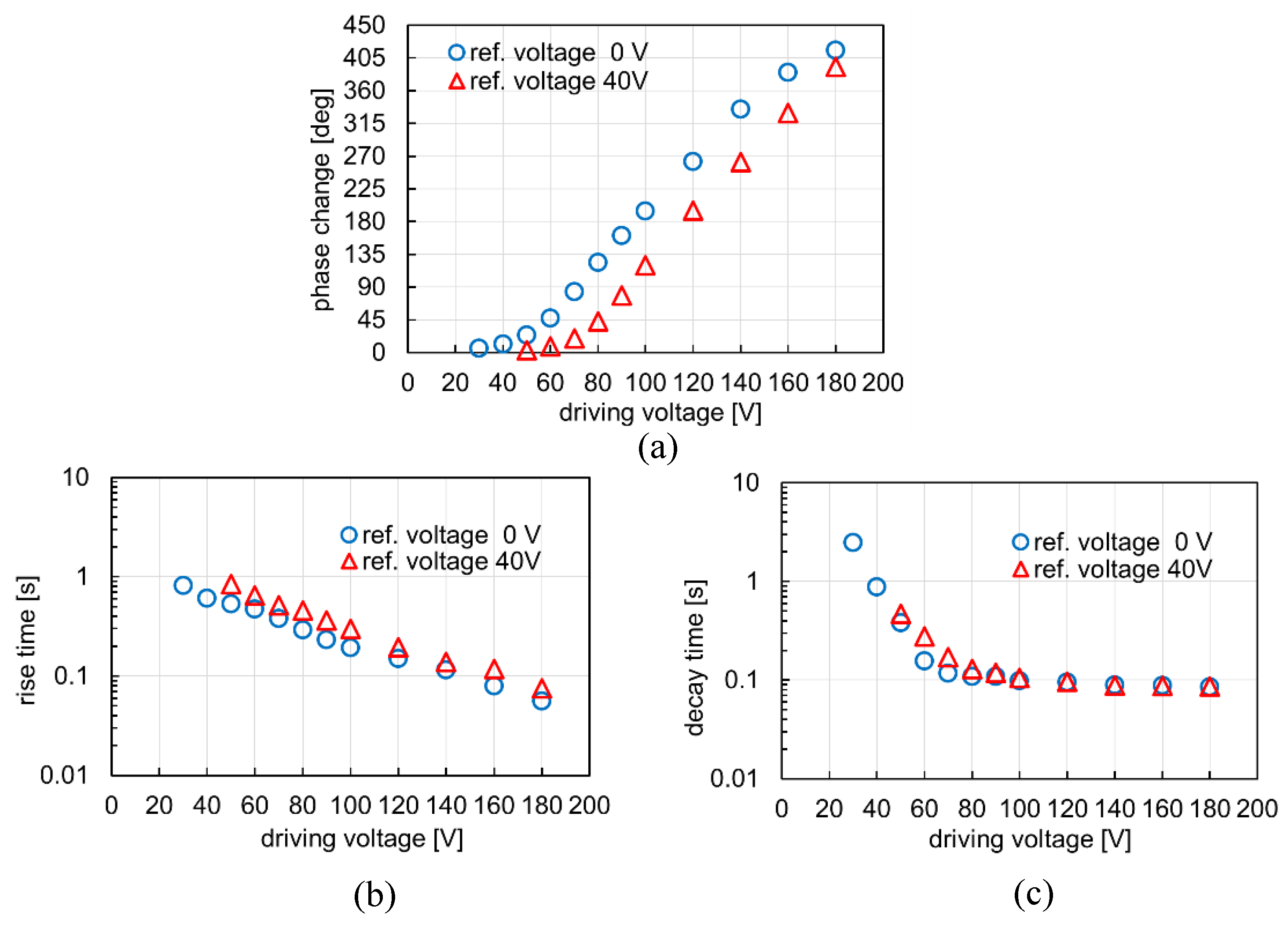
5.2. Improvement Results

Figure 10 shows the measurement results of the NRD waveguide type terahertz phase shifter using the pure NLC RDP-A3123 and NF/NLC RDP-A3123 complex with the thickness of 250 µm. First, it is easy to see that a large amount of phase change was obtained by using the NLC RDP-A3123 having a birefringence larger than that of the NLC 5CB. The phase change of the pure NLC 5CB is about 314° [8], while that of the pure NLC RDP-A3123 is about 365°.
Further, as shown in Figure 10a, the phase change of the NF/RDP-A3123 complex increases with increasing the driving electric field. A smaller value of the phase change than using the pure RDP-A3123 NRD can be obtained, but it increases continuously from 17° to 305° when a driving electric field is applied from 0.08 to 0.56 V/µm. That is, the NF/LC complex makes it possible to realize a variable phase shifter that has a wide phase change.
Figure 11 shows the applied electric field dependence of the permittivity of the pure NLC RDP-A3123 and the NF/RDP-A3123 complex with the thickness of 250 µm. Due to the limitations of the amplifier, we applied electric field up to 0.4 V/µm in the permittivity measurement. As shown in Figure 11, the permittivity of the pure NLC RDP-A3123 reaches saturation very quickly and for a relatively low electric field, while that of the NF/RDP-A3123 complex increases gradually and does not reach saturation with increasing electric field. It is easy to understand that the phase change is acting similarly. In the case of a waveguide loaded only with LC, the phase change reached its maximum value almost instantaneously and remained constant, while in the case where nanofibers are inserted, the phase change increases gradually and continuously. In the structure of the NF/LC complex, the LC molecules become difficult to move due to the alignment regulating force from the surrounding NFs. In addition, it was found that the phase change is also reduced because the permittivity of the NF/RDP-A3123 is smaller than that of the pure RDP-A3123.
As an example, we calculate the phase change when the electric field of 0.4 V/µm is applied. In the case of the pure RDP-A3123, the angle θ between the director of the LC molecules and the electric field direction of the terahertz wave is θ = 90°, the birefringence becomes Δ n = n e n o . From the results in Figure 8, the extraordinary refractive index n e and the ordinary refractive index n o of the NLC RDP-A3123 at 350 GHz are about 1.76 and 1.58, respectively. Consequently, the birefringence ∆n is about 0.18. We calculate the angle θ for the NF/RDP-A3123 complex. If ε / / and ε are defined as the permittivity in the long axis and short axis directions of the LC molecules, the permittivity ε ( V ) at an arbitrary driving voltage and the average tilt angle θ in the cell have the relationship as shown in following formula [35].
ε ( V ) = ε c o s 2 ( θ ) + ε / / s i n 2 ( θ )
or
θ = a r c s i n ε ( V ) ε ε / / ε
From Figure 12, the permittivity of the pure RDP-A3123 at 100 V is 31. If the tilt angle at that time is 90°, the permittivity of the NF/RDP-A3123 complex at 100 V is 22.2.
θ ( NF / LC ) = a r c s i n 22.2 5 31 5 54.4 °
here, the permittivity of both in the short axis direction is five. Under the same driving electric field of 0.4 V/µm, the tilt angle of the pure LC of 90° was reduced to about 54.4° for the NF/RDP-A3123 complex.
From Equation (1), the birefringence of the NF/RDP-A3123 is as follows.
Δ n ( θ ) = n e n 0 × n e n 0 2 × c o s 2 ( θ ) + n e 2 × s i n 2 ( θ )
Δ n ( 54.4 ° ) = 1.76 1.76 × 1.58 1.58 2 × c o s 2 ( 54.4 ° ) + 1.76 2 × s i n 2 ( 54.4 ° ) 0.1253
From Equation (2) for calculating the amount of phase change, the phase change of the NF/RDP-A3123 complex at the driving electric field of 0.4 V/µm can be predicted to be about 378° × 0.1253/0.180 = 263.1°. In measured results, the phase change is 270°, which almost agrees with the theoretical result.
The rise time decreases as the driving electric field increases. When the driving electric field is higher than 0.08 V/µm, it is 0.8 s or less. Besides, it was confirmed from Figure 10b that the rise time of NF/RDP-A3123 was increased. The reason is that the threshold voltage of the entire LC layer is increased by introducing the NFs into the LC layer. When a driving voltage is applied to the NLC, the threshold voltage V C at which the molecules start responding to the voltage is given by the following equation [36].
V C = π K ε 0 Δ ε
here, ε 0 is the permittivity in a vacuum, and ∆ε is the dielectric anisotropy of the LC. It can be seen from Equation (7) that the threshold voltage is constant without depending on the thickness of the LC layer. Therefore, when the pure LC is used, the threshold voltage does not change even if the thickness of the cell is changed. However, when NFs are used, since each NF operates as the interface, a threshold voltage is required for each NF and the threshold voltage for driving the entire LC increase. It can also be confirmed in Figure 11. Furthermore, when the NFs are inserted, the dielectric anisotropy decreases so that the rise time increases.
Finally, the decay time is about several hundred milliseconds under a low electric field but becomes about 0.15 s when enough electric field is applied, as shown in Figure 10c. Likewise, the decay time of the pure RDP-A3123 in about 150 s was reduced to about 1/1000, which is much shorter. With NF/RDP-A3123, the rise time of 0.8 s or less, and the decay time of about 0.15 s, and a large phase change that increases continuously from 17° to 305° can be obtained. It has been found that the decay time and rise time increases as the phase change decreases. It means that the response time may exceed 1 s to get a phase change of less than 17°. In the case of a waveguide length of 5 mm, the phase change is about 305° and is approaching saturation. To obtain a phase change of 360°, it is assumed that the waveguide length is extended to 6 mm (1.2 times) or RDP-94990 with a larger birefringence. Since the extension is not so long at 1 mm, a response time of 1 s or less can be kept without a significant increase in loss, and a variable phase shifter having a phase change of up to 360° can be realized. The research goals have been mostly achieved, but we will continue considering finding the phase shifter, which has more improvements. On the other hand, the use of RDP-94990 allows a larger amount of phase change without increasing the loss.
Figure 12 shows the phase change and response time of the NF/RDP-A3123 and the NF/RDP-94990 complex. As shown in Figure 12a, a larger amount of phase change was obtained by using the NLC RDP-94990 having a larger birefringence than the NLC RDP-A3123. The phase change of the NF/RDP-A3123 complex is about 305°, while that of the NF/RDP-94990 complex is about 410°. In the case of the NF/RDP-A3123 complex, the phase change starts to change quickly and reaches saturation when the driving electric field reaches 0.5 V/µm. In the case of the NF/RDP-94990 complex, the threshold voltage is higher, so the initial change is slow, and saturation has not yet been reached even when the driving electric field reaches 0.7 V/µm.
The rise time of the NF/RDP-94990 complex is longer than that of the NF/RDP-A3123 complex. However, when the driving electric field is larger than 0.12 V/µm, it is 0.8 s or less, so there is no problem in the application. When enough electric field is applied, the decay time is about 0.1 seconds. When obtaining a small phase change, the response time exceeding one second is a problem that exists in both the NF/RDP-A3123 complex and the NF/RDP-94990 complex. According to Equation (4), the rise time τ r of the LC molecule is inversely proportional to the dielectric anisotropy ∆ε and the square of the driving electric field E. As described above, the threshold voltage of NF/LC is large. In addition, when the driving electric field E is small, both the dielectric anisotropy ∆ε and the phase change amount of the complex are small, and the rise time is considerably long. An improved method for reducing the amount of phase change while applying a high driving electric field is conceived. We propose to increase the reference voltage as a simple improvement method. Increasing the initial alignment tilt angle (pretilt angle) of LC molecules under the influence of an electric field decreases the initial refractive index from the extraordinary refractive index n e to a smaller value, and the birefringence ∆n or phase change can be reduced. The decay time remains almost unaffected and unchanged. On the other hand, when the tilt angle is larger than 0, ε ( V ) > ε , and the dielectric anisotropy ∆ε decreases. Equation (4) indicates that the rise time may increase sharply. To avoid this problem, a reference voltage slightly higher than the threshold voltage is used. In this study, improvements were made under a reference voltage of 40 V. That is, the modulation depth of the AM wave of the driving voltage was changed from 100% to an appropriate value so that the initial voltage was 40 V instead of 0 V. Figure 13 shows the results of the improvement. Under the same driving voltage conditions, it was observed that the phase change amount was smaller with the reference voltage of 40 V, but a phase change amount from 3° to 392° can be obtained by driving voltage from 50 V to 180 V. The response time did not exceed one second even in the case of a small phase change amount, and a fully applicable phase shifter was realized.

6. Conclusions

We observed the distribution of the electric field component of the terahertz wave by simulation and confirmed that the NRD waveguide also works in the terahertz waveband with characteristics such as low loss and non-radiation. In addition, the NRD waveguided terahertz phase shifter loaded with the use of pure NLC can obtain a large phase change but has a very long decay time of several hundred seconds. To apply to an actual device, it is necessary to improve the decay time. We proposed improvement method with using NF/LC complex. Furthermore, two new types of NLC made by DIC Corporation, RDP-A3123 and RDP-94990 were used. RDP-A3123 has a smaller birefringence than RDP-94990 but has an excellent response time. Therefore, RDP-A3123 is preferentially used for improvement. By using the NF/LC complex, the decay time was greatly improved, and a largely variable phase change could be obtained. Although the rise time is longer, a response time of one second or less can be obtained if enough electric field is applied, so there is no problem in the application. In the case of NF/RDP-A3123 complex, the phase change is approaching saturation at about 305°, so to obtain a phase change of 360°, the waveguide length must be extended to 6 mm (1.2 times). In the case of NF/RDP-94990 complex, the applicable phase change exceeding 400° could be obtained, but there is a problem that the response time exceeds one second when the phase change is small. This problem was solved by changing the reference voltage from 0 V to 40 V. The applicable phase shifter with a response time of less than one second and a variable phase change up to 360° has been realized. It is thought that the NF/LC complex contributes to the realization of the NRD waveguide type terahertz variable phase shifter.

Author Contributions

Investigation, V.B.B. and Y.I.; supervision, H.M.; writing – original draft, T.N.L. All co-authors discussed the obtained results and read the paper. All authors have read and agreed to the published version of the manuscript.

Funding

This work was supported by JSPS KAKENHI Grant Number 19K15036.

Acknowledgments

The authors wish to thank DIC Corporation for providing the liquid crystal materials throughout this work.

Conflicts of Interest

The authors declare no conflict of interest.

References

  1. Itoh, T.; Rivera, J. A Comparative Study of Millimeter-Wave Transmission Lines. Infrared Millim. Waves 1983, 9, 95–132. [Google Scholar]
  2. Khoo, I.C.; Wu, S.T. Optics and Nonlinear Optics of Liquid Crystals; World Scientific: Singapore, 1993. [Google Scholar]
  3. Savo, S.; Shrekenhamer, D.; Padilla, W.J. Padilla, Liquid Crystal Metamaterial Absorber Spatial Light Modulator for THz Applications. Adv. Opt. Mater. 2014, 2, 275. [Google Scholar] [CrossRef]
  4. Wang, L. Self-activating liquid crystal devices for smart laser protection. Liq. Cryst. 2016, 43, 2062. [Google Scholar] [CrossRef]
  5. Wang, L.; Urbas, A.M.; Li, Q. Nature-Inspired Emerging Chiral Liquid Crystal Nanostructures: From Molecular Self-Assembly to DNA Mesophase and Nanocolloids. Adv. Mater. 2018, 30, 1801335. [Google Scholar] [CrossRef]
  6. Utsumi, Y.; Kamei, T.; Naito, R.; Saito, K. Measurement methods of nematic liquid crystal response time. Mol. Cryst. Liq. Cryst. 2005, 434, 337–352. [Google Scholar] [CrossRef]
  7. Lim, K.C.; Margerum, J.D.; Lackner, A.M. Liquid crystal millimeter wave electronic phase shifter. Appl. Phys. Lett. 1993, 62, 1065. [Google Scholar] [CrossRef]
  8. Bui, V.B.; Inoue, Y.; Moritake, H. NRD waveguide type terahertz phase shifter using Nematic liquid crystal. Jpn. J. Appl. Phys. 2019, 58, 22001. [Google Scholar] [CrossRef]
  9. Yoneyama, T. NRD Guide: New Approach to Millimeter Wave. IEEJ 1996, 116, 20–23. (In Japanese) [Google Scholar] [CrossRef] [Green Version]
  10. Kuroki, F.; Sugioka, M.; Matsukawa, S.; Ikeda, K.; Yoneyama, T. High Speed ASK Transceiver Based on the NRD Guide Technology at 60GHz band. IEEE Trans. Microw. Theory Tech. 1998, 46, 806–811. [Google Scholar] [CrossRef]
  11. Yoneyama, T. Millimeter wave integrated circuits using nonradiative dielectric waveguide. IEICE Trans. 1990, J73-C-I, 87–94. [Google Scholar] [CrossRef]
  12. Ekisho, B.H.I. Ekisho Binran; Maruzen Kabushikigaisha: Tokyo, Japan, 2000; pp. 108, 477. (In Japanese) [Google Scholar]
  13. Utsumi, Y.; Kamei, T.; Saito, K.; Moritake, H. Increasing the speed of microstrip-line-type polymer-dispersed liquid-crystal loaded variable phase shifter. IEEE Trans. Microw. Theory Tech. 2005, 53, 3345. [Google Scholar] [CrossRef]
  14. Geary, J.M.; Goodby, J.W.; Kmetz, A.R.; Patel, J.S. The mechanism of polymer alignment of liquid-crystal materials. J. Appl. Phys. 1987, 62, 4100. [Google Scholar] [CrossRef]
  15. Wang, Q.; Kumar, S. Submillisecond switching of nematic liquid crystal in cells fabricated by anisotropic phase-separation of liquid crystal and polymer mixture. Appl. Phys. Lett. 2005, 86, 71119. [Google Scholar] [CrossRef] [Green Version]
  16. Fujikake, H.; Kuki, T.; Nomoto, T.; Tsuchiya, Y.; Utsumi, Y. Thick polymer-stabilized liquid crystal films for microwave phase control. J. Appl. Phys. 2001, 89, 5295. [Google Scholar] [CrossRef]
  17. Lucchetta, D.E.; Karapinar, R.; Manni, A.; Simoni, F. Phase-only modulation by nanosized polymer-dispersed liquid crystals. J. Appl. Phys. 2002, 91, 6060. [Google Scholar] [CrossRef]
  18. Moritake, H.; Umeno, S.; Nguyen, T.; Higuchi, H.; Kikuchi, H. Microstrip-Line-Type Microwave Variable Phase Shifter Using Polymer Stabilized Nematic Liquid Crystal. In Proceedings of the 24th International Liquid Crystal Conference, Mainz, Germany, 19–24 August 2012; p. 176. [Google Scholar]
  19. Umeno, S.; Nguyen, T.; Higuchi, H.; Kikuchi, H.; Moritake, H. Polymer Stabilized Nematic Liquid Crystal with Thermal Polymerization for Microwave Application. In Proceedings of the 1st Asian Liquid Crystal Conference, Yamanashi, Japan, 16–18 December 2012; p. 52. [Google Scholar]
  20. Nguyen, T.; Umeno, S.; Higuchi, H.; Kikuchi, H.; Moritake, H. Improvement of decay time in nematic-liquid-crystal-loaded coplanar-waveguide-type microwave phase shifter by polymer stabilizing method. Jpn. J. Appl. Phys. 2014, 53, 01AE08. [Google Scholar] [CrossRef]
  21. Bui, V.B.; Inoue, Y.; Higuchi, H.; Kikuchi, H.; Moritake, H. Response improvement of microstrip line type microwave millimeter wave phase shifter using photopolymerizable polymer stabilized nematic liquid crystal. IEEJ Trans. FM 2017, 137, 356–362. (In Japanese) [Google Scholar] [CrossRef]
  22. Duong, T.Q.; Kobayashi, H.; Inoue, Y.; Moritake, H. Improved response time of thick liquid crystal device by using electrospun nanofiber. Jpn. J. Appl. Phys. 2017, 56, 61701. [Google Scholar] [CrossRef]
  23. Sill, T.J.; von Recum, H.A. Electrospinning: Applications in drug delivery and tissue engineering. Biomaterials 2008, 29, 1989. [Google Scholar] [CrossRef]
  24. Bolanda, E.D.; Colemana, B.D.; Barnesa, C.P.; Simpsonb, D.G.; Wnekc, G.E.; Bowlina, G.L. Electrospinning polydioxanone for biomedical applications. Acta Biomater. 2005, 1, 115. [Google Scholar] [CrossRef]
  25. Lee, K.Y.; Jeong, L.; Kang, Y.O.; Lee, S.J.; Park, W.H. Electrospinning of polysaccharides for regenerative medicine. Adv. Drug Deliv. Rev. 2009, 61, 1020–1032. [Google Scholar] [CrossRef] [PubMed]
  26. Shah, P.N.; Manthe, R.L.; Lopina, S.T.; Yun, Y.H. Electrospinning of L-tyrosine polyurethanes for potential biomedical applications. Polymer 2009, 50, 2281. [Google Scholar] [CrossRef]
  27. Nirmala, R.; Navamathavan, R.; Kang, H.S.; El-Newehy, M.H.; Kim, H.Y. Preparation of polyamide-6/chitosan composite nanofibers by a single solvent system via electrospinning for biomedical applications. Biointerfaces 2011, 83, 173. [Google Scholar] [CrossRef] [PubMed]
  28. Agarwal, S.; Wendorff, J.H.; Greiner, A. Use of electrospinning technique for biomedical applications. Polymer 2008, 49, 5603–5621. [Google Scholar] [CrossRef] [Green Version]
  29. Dong, Z.; Kennedy, S.J.; Wu, Y. Electrospinning materials for energy-related applications and devices. J. Power Sources 2011, 196, 4886. [Google Scholar] [CrossRef]
  30. Raut, H.K.; Nair, A.S.; Dinachali, S.S.; Ganesh, V.A.; Walsh, T.M.; Ramakrishna, S. Porous SiO2 anti-reflective coatings on large-area substrates by electrospinning and their application to solar modules. Sol. Energy Mater. Sol. Cells 2013, 111, 9–15. [Google Scholar] [CrossRef]
  31. Wang, L.; Ding, C.X.; Zhang, L.C.; Xu, H.W.; Zhang, D.W.; Cheng, T.; Chen, C.H. A novel carbon–silicon composite nanofiber prepared via electrospinning as anode material for high energy-density lithium ion batteries. J. Power Sources 2010, 195, 5052–5056. [Google Scholar] [CrossRef]
  32. Li, X.; Gao, C.; Wang, J.; Lu, B.; Chen, W.; Song, J.; Zhang, S.; Zhang, Z.; Pan, X.; Xie, E. TiO2 films with rich bulk oxygen vacancies prepared by electrospinning for dye-sensitized solar cells. J. Power Sources 2012, 214, 244–250. [Google Scholar] [CrossRef]
  33. Hasani-Sadrabadi, M.M.; Shabani, I.; Soleimani, M.; Moaddel, H. Novel nanofiber-based triple-layer proton exchange membranes for fuel cell applications. J. Power Sources 2011, 196, 4599–4603. [Google Scholar] [CrossRef]
  34. Sivakkumar, S.R.; Oh, J.S.; Kim, D.W. Polyaniline nanofibres as a cathode material for rechargeable lithium-polymer cells assembled with gel polymer electrolyte. J. Power Sources 2006, 163, 573. [Google Scholar] [CrossRef]
  35. Tanaka, I.; Hori, F.; Muko, A. Ekisho Nyumon; Saiwai Shobou: Tokyo, Japan, 1992; p. 168. (In Japanese) [Google Scholar]
  36. Setsuhara, H. Ekisho No Butsuri; Uchida Rokakuho: Tokyo, Japan, 2004; p. 50. (In Japanese) [Google Scholar]
Figure 1. Simulation model of basic non-radiative dielectric (NRD) waveguide.
Crystals 10 00307 g001
Figure 2. Simulation results of basic NRD waveguide at 350 GHz (a) z = 0 plane, (b) y = 1 plane, and (c) and (d) enlarged view of y = 1 plane.
Crystals 10 00307 g002
Figure 3. Structure of liquid crystal-loaded NRD waveguided terahertz wave phase shifter and cross-sections of (a) pure liquid crystal (LC) cell and (b) nanofiber (NF)/LC cell.
Crystals 10 00307 g003
Figure 4. Conceptual diagram of an aligned nanofiber/liquid crystal complex. (Left) shows SEM image of aligned nanofiber. (Center) and (Right) show nanofiber and liquid crystal in the structure of complex and NF/LC cell.
Crystals 10 00307 g004
Figure 5. Basic schematic of the electrospinning system.
Crystals 10 00307 g005
Figure 6. Block diagram of the permittivity measurement system.
Crystals 10 00307 g006
Figure 7. Block diagram of the terahertz wave measurement system.
Crystals 10 00307 g007
Figure 8. (a) refractive indexes, (b) birefringences, and (c) absorbances of 5CB, RDP-A3123, and RDP-94990 between 300 GHz and 500 GHz.
Crystals 10 00307 g008
Figure 9. Electric field dependencies of (a) rise time and (b) decay time of 5CB, RDP-A3123, and RDP-94990.
Crystals 10 00307 g009
Figure 10. Electric field dependencies of (a) phase change, (b) rise time, and (c) decay time in NF/RDP-A3123 complex and pure RDP-A3123.
Crystals 10 00307 g010
Figure 11. Comparison of permittivity between NF/RDP-A3123 complex and pure RDP-A3123.
Crystals 10 00307 g011
Figure 12. Electric field dependencies of (a) phase change, (b) rise time, and (c) decay time in NF/RDP-94990 complex and NF/RDP-A3123 complex.
Crystals 10 00307 g012
Figure 13. Driving voltage dependencies of (a) phase change, (b) rise time, and (c) decay time in NF/RDP-94990 complex with reference voltage 0 V and 40 V.
Crystals 10 00307 g013
Table 1. Phase transition temperatures and viscosities of the nematic LCs (NLCs); 5CB, RDP-A3123, and RDP-94990.
NLCsPhase Transition Temperature
(°C)
Viscosity
(mPa·s)
Crystal-NematicNematic-Isotropic
5CB243522.5
RDP-A3123−388960.4
RDP-94990−308640.9

