Abstract
Advanced materials with high strength are in great demand for structural applications, such as in aerospace. It has been proved that fabrication strategy plays a vital role in producing composites to satisfy these needs. This study explores new strategies for flake powder metallurgy, with the aim of designing an effective strategy to achieve the highest possible mechanical strength for a metal matrix nanocomposite without changing the reinforcement fraction. Different strategies were used to regulate the mechanical properties for similar composites based on shift speed ball milling. Ultra-ductile composites on one hand, and ultra-strong composites on the other hand, were fabricated using similar composites. The results demonstrate that shifting the ball milling speed can be used to manipulate the mechanical properties of the composite to achieve the desired properties for any specific application.
1. Introduction
Lightweight materials with high strength are of great importance for their potential to reduce energy consumption and environmental pollution [1] in a wide range of engineering applications, such as aerospace and transportation [2]. Metal matrix composites (MMCs) have exceptional prospects for use in such applications [3]. Integrating reinforcements into the aluminum matrix can improve the strength, hardness, and other pro0perties of the matrix [4,5]. Aluminum matrix composites reinforced by ceramic particles also have a low thermal expansion coefficient, distinguishing them to be used in defense, cosmonautics, the automotive industry, and many other areas [6,7,8]. SiC particulates are among the most used reinforcements to strengthen the aluminum matrix [9,10,11]. Nonetheless, the great degradation of some properties, such as ductility, in aluminum MMCs reinforced with SiC microparticles is a key challenge [12,13,14]. Tjong reported that the tendency of large ceramic particulates to be cracked during mechanical loading can result in lower ductility and premature failure [15]. Thus, to tackle these drawbacks, the interest was transferred towards nanosized reinforcements to produce metal matrix nanocomposites (MMNCs) that postulate more superior mechanical properties [16,17]. A very important attribute leading to this superiority is the minimization of particle-based damage mechanisms, while they are predominant with microparticle reinforcement [18].
In addition to these reinforcement-related factors, the selected production process and its conditions affect the produced MMNCs [19]. Therefore, many fabrication strategies are developed and their conditions are manipulated to manufacture aluminum MMNCs incorporating nanoparticles [20]. Fabrication techniques for manufacturing MMNCs can be categorized into two main categories: solid-state and liquid-state processing. Each of these categories has its own paybacks and drawbacks [21]. Drawbacks of liquid-state processing methods, such as stirring, include agglomeration, poor wetting of ceramic nanoparticles with molten metal [22], and chemical interfacial reaction [19], limiting their utilization. These drawbacks make solid-state manufacturing processes more promising.
Solid-state techniques normally involve a powder metallurgy (PM) process. In PM, the powders of both the reinforcement and the base matrix are mixed together, compacted, and then sintered [23,24] to form a final composite. PM, as a simple, adaptable, and net-shape-efficient technique, when implemented using high-energy ball milling (HEBM) [25], can effectively engage the ball–powder–ball collisions to incorporate the reinforcement with uniform distribution [26,27]. Nevertheless, the PM process is not the ultimate choice with nanoparticles, especially when the difference between the size of the matrix and the reinforcement is visible [28]. In other words, in a solid-state process such as PM, it is highly possible for nanoparticles to be agglomerated [29], complicating the formability of the produced composites [30,31,32]. Thus, it is essential to develop a simple and operational method capable of uniform dispersion of nanoparticles, allowing for sufficient deformation of the produced composites, and improving the mechanical properties [33].
The past few years have witnessed the emergence of a sophisticated strategy to synthesize MMNCs called flake powder metallurgy (FPM). Morsi and Esawi [34] reported the flattening of aluminum particles to form a flake shape at the initial stage of mechanical milling. Furthermore, Razavi et al. [35] confirmed this phenomena, signifying the benefits of these flakes’ shape to adapt nanoreinforcement. Additionally, Tjong [15] reported the fragmentation of these flaky shapes as a result of a longer ball milling time, such as 24 h. In 2011, Jiang et al. [36] reported, for the first time, a new strategy and called it flake powder metallurgy. In this strategy, aluminum flakes coated with Al2O3 skins can be used as bases to build up the new material in an organized approach, rather than leaving it to build up randomly as in the situation of spherical powder. Additionally, they divided the typical FPM process into three steps: flake powder preparation, composite powder production, and bulk composite consolidation. In [37], they worked to produce a strong, and yet ductile, Al/CNT nanocomposite, with 435 MPa strength and 0.06 ductility. They attributed these results to the capability of their methodology to tackle the problem confronted with conventional PM. Furthermore, Kai et al. [38] utilized FPM with the aim of simultaneously enhancing the strength and ductility of the fabricated composite, achieved a strength and ductility of 364 MPa and 0.09 respectively, and ascribed the enhanced ductility to the effect of improved normalized strain hardening. In [33], FPM was employed, confirming its capability to disperse a high volume fraction of reinforcements with uniform distribution, and high strength was achieved without trading the ductility. Additionally, Fan et al. [39] assured that high strength and good ductility of fabricated composite can be obtained by a carefully designed FPM. They also discussed some challenges that need to be tackled with FPM. Indeed, a number of investigations [40,41,42,43,44,45,46] have been published regarding different aspects of FPM in recent years. For example, Varol et al. [41] combined the first and second steps of FPM into one, successfully.
With the continuous development of FPM, in 2017, Xu et al. [27] proposed and applied a strategy for the sake of ductility improvement without trading the strength. They named this strategy shift-speed ball milling (SSBM), because it combines low and high speed in one process to acquire the gains of both speeds. They stated that their results were very promising and accredited that to achieving uniform dispersion and good interfacial bonding.
Accordingly, the implementation of a shift-speed process in FPM was studied with different composites [47,48,49]. However, it is basic to clarify that the shift-speed in these studies used only two different speeds. Therefore, the effect of multi-speeds is an undeniable consideration to investigate. From this view, this study planned to explore the effect of applying different fabrication strategies by shifting the ball milling speed up and down. The intention was to regulate the mechanical properties of the nanocomposite incorporating a similar concentration of SiC nanoparticles.
2. Materials, Methods, and Experiments
2.1. Materials
Fine aluminum powder of 98% purity and 30-µm average size, obtained from Loba Chemie (India), and nanosized β-SiC of 95% purity and 60-nm average size, obtained from Alfa Aesar (Germany), were used as raw materials in this study. Steric acid was used as a process control agent to avoid severe cold welding during the ball milling process.
2.2. Ball Milling Strategies
Three different ball milling strategies—2-speeds, 3-speeds-last down, and 3-speeds-up—were utilized to observe the effectiveness of changing the ball milling speed on the uniform distribution of nanoparticle reinforcement within aluminum MMNCs. Additionally, the mechanisms of these different synthesizing strategies, described in Table 1, were explained. A fixed amount, 8 wt.%, of SiC nanoparticles were blended with aluminum powder, 2 wt.% of stearic acid was used in the mixture, and the ball-to-powder ratio was fixed at 15:1. The ball milling was run continuously, alternating between 15 min of milling and 15 min of intermediate stops to allow for cooling. The ball milling stages are described clearly in Table 1.

Table 1.
Designation system.
The synthesized nanocomposite powders were consolidated using a high-frequency induction heat sintering furnace (HFIHS) from ELTek Co., South Korea. In this consolidation process, compaction and sintering was conducted simultaneously in 5 min. In the HFIHS, the temperature was generally held at approximately 20% lower than the solidus temperature of the base materials being processed: 570 °C, in this current study. This was to maintain the aluminum elements in their solid state and to avoid the formation of a liquid phase. The fabrication dies in the process were made of graphite with a 10-mm inner diameter. The die was filled with ball-milled powder, closed by two punches from each side, and placed in an evacuated chamber. A uniaxial pressure of 40 MPa was applied through the sintering process. The required heat for the sintering process was generated at 150 °C/min by applying a strong magnetic field.
2.3. Investigations and Testing
To explore the developed strategies, a number of investigations and tests were conducted throughout the production process. Upon receiving, raw materials were characterized using field emission scanning electron microscopy (FESEM) Model: JEOL JSM-7600F, Tokyo, Japan. Moreover, the ball-milled powder was investigated by FESEM to find out about the evolution of the powder morphology, the change of particles shapes and sizes, and the homogeneity of reinforcement distribution. The consolidated bulk composites were polished, and their sizes and actual densities were measured and recorded. The measurements of actual densities were obtained using Archimedes’ method. Additionally, X-ray diffraction (XRD) Model: D-8 Discover, Bruker, Berlin, Germany was used to examine the bulk composite. From these XRD patterns, the crystallite size and microstrain were obtained. Vickers hardness tester (WOLPERT UH930, Wilson Hardness, Shanghai, China) was used to measure the hardness of the polished bulk composites at a 5-kN load. The Instron 5582 Microtester (Instron, University Ave, Norwood, USA) was used to test the compressive property according to ASTM: E9-89a at room temperature with a strain rate of 10−3/s.
3. Results and Discussions
3.1. Morphology Analysis
Upon receiving the raw materials, FESEM was employed to characterize both the base matrix (aluminum powder) and the reinforcement (SiC powder) as shown in Figure 1. It can be seen in Figure 1a that the aluminum particles are either small and spherical or large and irregular. Additionally, Figure 1b shows the SiC nanoparticles are agglomerated. This agglomeration is confirmed by the high-resolution transmission electron microscope (HRTEM) image in Figure 1c. Additionally, Figure 1 confirms the size as stated by the manufacturers of the powders.
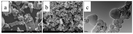
Figure 1.
FESEM images of (a) Al powders and (b) SiC powder, and HRTEM image of (c) SiC powder.
To investigate the effect of the implemented strategies on the morphology evolution, FESEM was utilized on the ball-milled powder produced by each strategy as presented in Figure 2. Figure 2a,b represent the powder produced by the two-speed strategy. As can be seen, the principal characteristic of the ball-milled powder using this strategy is the flake shapes of the majority of the particles with uniform size. Additionally, a minor number of small particles are broken, as indicated by the white arrows in Figure 1a. Additionally, a close look at these particles shows their roughness, as seen inside the black circles in Figure 2a, which when magnified, as in Figure 2b, appears more obvious. The reason behind this rough surface could be the predomination of fracturing at this stage [50]. The agglomeration of SiC in this powder is moderate with clusters of few particles, as denoted by the black circles in Figure 2b.
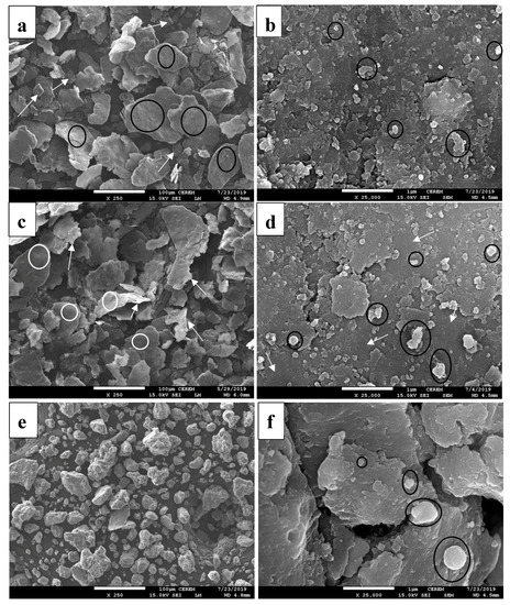
Figure 2.
FESEM images for powder produced by (a,b) two-speeds, (c,d) three-speeds-last down, and (e,f) three-speeds all up.
Regarding three speeds, including the downshifting of the milling speed at the last stage results in the minimization of the compressive force and the maintenance of the shearing force. This downshifting smoothens the surface and reduces the thickness while the flaky shape is still preserved. These characteristics are indicated in Figure 2c,d. The surface smoothening is indicated by white circles in Figure 2c and white arrows in Figure 2d. The reduction in the thickness of the aluminum particles is indicated by white arrows in Figure 2c. These phenomena could be due to the predomination of welding in this case. Moreover, the presence of agglomerated SiC in this case seems to be the highest among all three cases. This is attributed to removing the SiC that is not bonded enough.
Finally, in the case of three speeds all shifted up, the powder morphology appears totally different, as can be seen in Figure 2e, where the flake shape has transformed into an equiaxed shape. It can be said that the powder reached the steady state due to the balance between welding and fracturing [50]. Some of Al flakes were welded together, producing larger particles. This is because the shifting of the ball milling speed upward increased the compressive force. Moreover, the agglomeration of SiC is very low and hardly seen, where few particles present in each cluster, as seen in Figure 2f. Additionally, there are only few clusters in this sample in comparison with those in the second case. It is worth mentioning that the lower number of SiC nanoparticles in those clusters implies a homogenous dispersal of SiC nanoparticles in the synthesized powder by all three strategies applied in this study.
For confirmation of SiC nanoparticles in the powder mixture, Energy-dispersive X-ray spectroscopy (EDX) elemental analysis is presented in Figure 3. The analysis shows a high concentration of SiC content in Figure 3a,b for both point and area spots on the white particles respectively, which confirms that it is either single or agglomerated SiC particles. Meanwhile, it shows 0% SiC content when spotting on the pure Al areas as in Figure 3c.
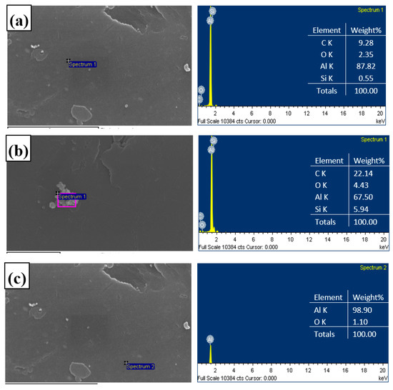
Figure 3.
EDS analysis for the powder composite: (a) point spot on SiC single particle, (b) area spot on SiC agglomerated particles, and (c) point spot on Al base matrix.
3.2. Density and Measurements
The HFIHS system was used to consolidate the ball-milled powder to produce bulk composites as shown in Figure 4. Each sample has a 10-mm diameter, where its other physical measurements are presented in Table 2.
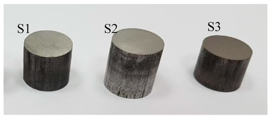
Figure 4.
Set of consolidated bulk composites.
Table 2.
Measurements and densities of bulk composites.
The low relative density of S2 can be ascribed to the agglomeration of SiC particles in this sample preventing total densification during sintering. Moreover, the relative density of S3 is very high, attributed to the effectiveness of this strategy in dispersing the SiC nanoparticles uniformly within the matrix, and consequently producing the suitable powder particle to achieve fully dense nanocomposites.
3.3. XRD Analysis
XRD was employed to investigate the consolidated composites. The patterns of the three samples are presented in Figure 5. For reference, the patterns of pure Al and SiC are also included in Figure 5.
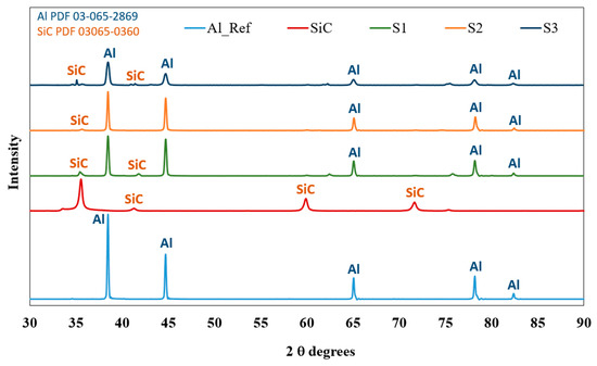
Figure 5.
XRD pattern for Al/SiC bulk compo
XRD analysis can be used to investigate the presence of SiC in the produced composites. Thus, the XRD patterns of the bulk composites by the three strategies have shown SiC peaks. Additionally, the Al peaks are broadened, and their intensities are diminished. Additionally, there is a detectable peak in S1 and S3 around 63 degrees, indicating the formation of Al2O3. This is attributed to the oxidation process taking place after the ball milling process. The absence of this peak in S2 is due to the lower energy at the last stage of this process in comparison with the other samples.
To compare the broadening of peaks and the diminishing in their intensities, Figure 6 is presented. This figure shows that the spectrum of S1 has a diminished intensity with a small broadening. Mostly, a similar behavior can be seen in S2. However, the S2 peak is slightly narrower than the peak of S1, which can be attributed to the increase of the crystallite size of S2 narrowing the peak width, and the higher porosity in the S2 narrowing the peak intensity. Additionally, the huge broadening and intensity diminishing among all three samples can be seen in S3. This indicates that S3 has the lowest crystallite size and the highest microstrain, as can be seen in Figure 6. Crystallite size and microstrain were calculated by obtaining and full width at half maximum (FWHM) directly from DIFFRAC.EVALUATION PACKAGE software. The crystallite size was then calculated using the following equation:
The microstrain was calculated using the following equation: .
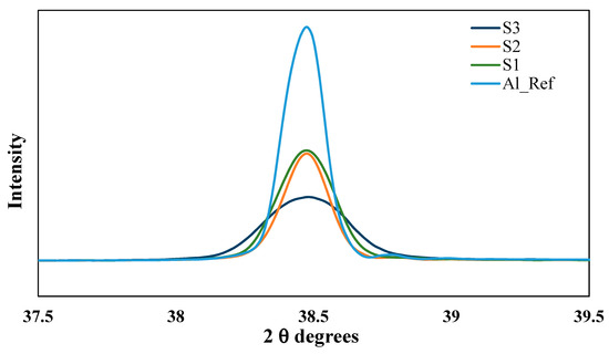
Figure 6.
Magnified first Al peaks for the bulk composites.
It should be mentioned here, in Figure 7, that these calculations were used as indicative, and used in process explanation. However, it is not to validate the exact crystallite size.
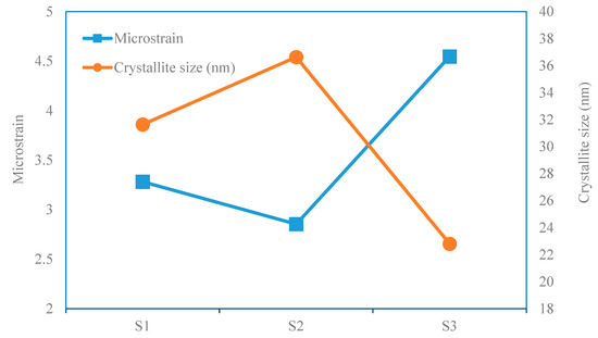
Figure 7.
Microstrain and crystallite size for the produced bulk composites by each strategy.
3.4. Process Mechanisms
The mechanisms of the implemented strategies can be described based on the above analysis. The main differences between the implemented strategies are in the number and direction of speed shifting. The first strategy includes two speeds, the second adds to this a shift down, and the third replaces this last shift to be up instead of down.
To illustrate these mechanisms, two figures are presented. Figure 8 simulates the shape of the produced powders, and Figure 9 describes the motion that leads to these shapes.
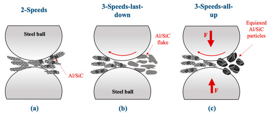
Figure 8.
Illustration of the resultant powder of the last stage of each strategy. (a) 2-Speeds, (b) 3-speeds-last-down, (c) 3-speeds-all up
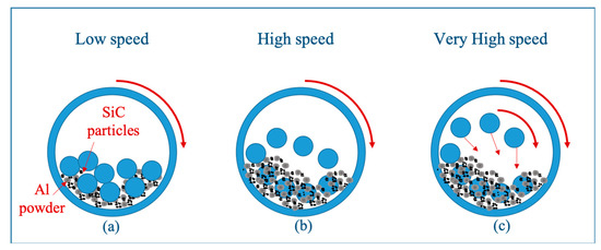
Figure 9.
Schematic of the balls motion with increasing speed. (a) low speed, (b) high speed, (c) very high speed.
The morphology of the resultant ball-milled powder in the last stage of the first strategy, illustrated in Figure 8a, shows that the aluminum powders have converted into flake shapes and the reinforcements are distributed on top of them with low agglomeration. This is attributed to the type of motion during the ball milling process. In this strategy, the process includes two stages: low speed, followed by high speed, as schematically represented in Figure 9. In the first stage (low speed), the collisions are dominated by shearing force leading to the flattening of aluminum particles and distributing the reinforcements. This stage was studied in previous investigations and has been proven to produce flaky shape particles, allowing reinforcements to be distributed uniformly in the matrix powder [39]. In the second stage (high speed), the compressive force is increased leading to the incorporation of some reinforcement particles into these flakes, but some of them are not bonded enough.
In the second strategy, an additional stage is added by shifting the speed back to low speed. The entering powder is the one exiting from the previous strategy. Additionally, the morphology of the resultant ball-milled powder (Figure 8b), shows smoother surface and increased agglomeration. This is attributed to reducing the compressive force allowing the shearing force to dominate again, removing the reinforcements that lack enough bonding with neighboring aluminum particles.
The last strategy replaces the last stage with very high speed. The morphology of the resultant ball-milled powder has converted into equiaxed shape (Figure 8c). This is attributed to the effectiveness of the last stage (very high speed) (Figure 9c), in maintaining a balance between fracturing and cold welding. Additionally, it incorporates the reinforcement effectively within the aluminum matrix.
3.5. Mechanical Properties
3.5.1. Hardness Results
The microhardness of the consolidated samples was tested by the Vickers microhardness method and recorded. The average of three records for each sample is used and presented in Figure 10.
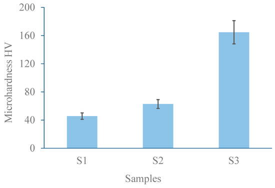
Figure 10.
Microhardness results.
The implemented strategies clearly have different effects on the microhardness results. The lower hardness of the S1 sample can be attributed to the lower alloying time in this strategy compared to the other two strategies. In contrast, the S2 bulk composite has a slightly enhanced hardness due to the further alloying, even though this further alloying was at low speed and for a shorter time. Additionally, a huge improvement can be seen in the S3 bulk composite produced by the three-speeds-all up strategy, which is 164% and 264 % higher than that of S2 and S1, respectively. This can be attributed to the unprecedented design of this strategy, taking the advantages of flake powder metallurgy via speed shifting and utilizing the steady state. This strategy combines enough interfacial bonding of the Al/SiC, uniform distribution of SiC, and the task allocation for SiC nanoparticles to restrict the dislocations movement.
3.5.2. Compression Results
The stress–strain uniaxial compression results of 8 wt.% SiC/Al bulk composites consolidated from ball-milled powder synthesized by different ball milling strategies are shown in Figure 11.
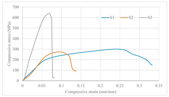
Figure 11.
stress-strain uniaxial compression curves.
The analysis of the curves in Figure 11 has shown that S1 has the highest total compressive strain. This is attributed to the lower alloying time. S2, in contrast has both a lower compressive stress and strain. This is attributed to the long alloying time, increasing the brittleness. Additionally, the agglomeration of the reinforcement and lack of bonding lowered the strengthening. The S3 curve, in contrast, has a very high strength, reaching more than 200% of that of S1 samples. This is attributed to the effectiveness of the strategy, used to produce the composite of this sample, in increasing the strength of the composite to its highest possible value.
4. Conclusions
Three strategies were implemented in this study to regulate the mechanical properties of an aluminum matrix reinforced by 8% of SiC. It has been found that, with the same composite, the fabrication strategy can lead to ultra-ductile composite by utilizing a two-speed strategy. On the other hand, utilizing a three-speed strategy can produce an ultra-strong composite. The process mechanism for each strategy was illustrated based on the scientific background of powder metallurgy. The analysis of the morphological evolutions of the resulting powders was used to explain these mechanisms. The conclusions can be summarized as follows:
- -
- Two-speed ball milling was able to produce an ultra- ductile nanocomposite. In this strategy, the underlying mechanism of particle deformation and reinforcement dispersion includes the transformation of Al particles into flake shapes, with some fractured particles and a uniform dispersion of reinforcement but lacking sufficient bonding.
- -
- In the second strategy, the process mechanism shows the smoothing of the surface of the particles and the reduction of their thickness as a result of decreasing the compressive force. The long ball milling has resulted in increased brittleness, and the agglomeration prevented any effective strengthening due to a lack of work hardening.
- -
- In the third strategy, the process mechanism has shown that the powder transforms into an equiaxed shape, verifying that the ball milling process reached a steady state. The reinforcement is uniformly distributed, and the interfacial bonding is strong. This is also confirmed by the high enhancement of the compressive strength (200%) and hardness (264%) in comparison with the first strategy.
These findings assure that FPM strategies, when carefully designed, can be the path towards energy saving by tailoring the mechanical properties of the composites without any need to add more weight.
Author Contributions
Conceptualization, S.M.A. and H.S.A.; methodology, S.M.A. and H.S.A.; validation, S.M.A.; formal analysis, S.M.A. and N.H.A.; investigation, S.M.A. and H.S.A.; resources, N.H.A.; data curation, S.M.A., N.H.A. and H.S.A.; writing—original draft preparation, S.M.A.; writing—review and editing, S.M.A. and H.S.A.; supervision, N.H.A.; funding acquisition, S.M.A. and N.H.A. All authors have read and agreed to the published version of the manuscript.
Funding
This research was funded by research and development office at ministry of education of Saudi Arabia RDO-MOE Postdoctoral Fellowship Program, grant number PFP-181903.
Acknowledgments
The authors acknowledge the Deanship of Scientific Research (DSR), King Saud University (KSU) for their support. The authors also thank the DSR and RSSU at KSU for their technical support.
Conflicts of Interest
The authors declare no conflict of interest.
References
- Zhang, X.; Li, S.; Pan, B.; Pan, D.; Liu, L.; Hou, X.; Chu, M.; Kondoh, K.; Zhao, M. Regulation of interface between carbon nanotubes-aluminum and its strengthening effect in CNTs reinforced aluminum matrix nanocomposites. Carbon 2019, 155, 686–696. [Google Scholar] [CrossRef]
- Selvakumar, N.; Gnanasundarajayaraja, B.; Rajeshkumar, P. Enhancing the properties of Al–WC nanocomposites using liquid metallurgy. Exp. Technol. 2016, 40, 129–135. [Google Scholar] [CrossRef]
- Marimuthu, S.; Dunleavey, J.; Liu, Y.; Smith, B.; Kiely, A.; Antar, M. Characteristics of hole formation during laser drilling of SiC reinforced aluminium metal matrix composites. J. Mater. Process. Technol. 2019, 271, 554–567. [Google Scholar] [CrossRef]
- Akbari, M.K.; Rajabi, S.; Shirvanimoghaddam, K.; Baharvandi, H.R. Wear and friction behavior of nanosized TiB2 and TiO2 particle-reinforced casting A356 aluminum nanocomposites: A comparative study focusing on particle capture in matrix. J. Compos. Mater. 2015, 49, 3665–3681. [Google Scholar] [CrossRef]
- Akbari, M.K.; Baharvandi, H.R.; Shirvanimoghaddam, K. Tensile and fracture behavior of nano/micro TiB2 particle reinforced casting A356 aluminum alloy composites. Mater. Des. 2015, 66, 150–161. [Google Scholar] [CrossRef]
- Kaczmar, J.W.; Pietrzak, K.; Włosiński, W. The production and application of metal matrix composite materials. J. Mater. Process. Technol. 2000, 106, 58–67. [Google Scholar] [CrossRef]
- Wang, Z.; Song, M.; Sun, C.; Xiao, D.; He, Y. Effect of extrusion and particle volume fraction on the mechanical properties of SiC reinforced Al–Cu alloy composites. Mater. Sci. Eng. A 2010, 527, 6537–6542. [Google Scholar] [CrossRef]
- Prasad, S.V.; Asthana, R. Aluminum metal–matrix composites for automotive applications: Tribological considerations. Tribol. Lett. 2004, 17, 445–453. [Google Scholar] [CrossRef]
- Grácio, J.J.; Picu, C.R.; Vincze, G.; Mathew, N.; Schubert, T.; Lopes, A.; Buchheim, C. Mechanical behavior of Al-SiC nanocomposites produced by ball milling and spark plasma sintering. Metall. Mater. Trans. A 2013, 44, 5259–5269. [Google Scholar] [CrossRef]
- Wu, Y.; Kim, G.-Y.; Anderson, I.E.; Lograsso, T.A. Fabrication of Al6061 composite with high SiC particle loading by semi-solid powder processing. Acta Mater. 2010, 58, 4398–4405. [Google Scholar] [CrossRef]
- Vanarotti, M.; Shrishail, P.; Sridhar, B.R.; Venkateswarlu, K.; Kori, S.A. Surface modification of SiC reinforcements & its effects on mechanical properties of aluminium based MMC. Appl. Mech. Mater. 2014, 446–447, 93–97. [Google Scholar]
- Mousavian, R.T.; Khosroshahi, R.A.; Yazdani, S.; Brabazon, D.; Boostani, A.F. Fabrication of aluminum matrix composites reinforced with nano- to micrometer-sized SiC particles. Mater. Des. 2016, 89, 58–70. [Google Scholar] [CrossRef]
- Mazahery, A.; Shabani, M.O. Nano-sized silicon carbide reinforced commercial casting aluminum alloy matrix: Experimental and novel modeling evaluation. Powder Technol. 2012, 217, 558–565. [Google Scholar] [CrossRef]
- Fogagnolo, J.B.; Ruiz-Navas, E.M.; Robert, M.H.; Torralba, J.M. The effects of mechanical alloying on the compressibility of aluminium matrix composite powder. Mater. Sci. Eng. A 2003, 355, 50–55. [Google Scholar] [CrossRef]
- Tjong, S.C. Novel nanoparticle-reinforced metal matrix composites with enhanced mechanical properties. Adv. Eng. Mater. 2007, 9, 639–652. [Google Scholar] [CrossRef]
- Ahamed, H.; Senthilkumar, V. Role of nano-size reinforcement and milling on the synthesis of nano-crystalline aluminium alloy composites by mechanical alloying. J. Alloys Compd. 2010, 505, 772–782. [Google Scholar] [CrossRef]
- Schmidt, A.; Siebeck, S.; Götze, U.; Wagner, G.; Nestler, D. Particle-reinforced aluminum matrix composites (AMCs)—Selected results of an integrated technology, user, and market analysis and forecast. Metals 2018, 8, 143. [Google Scholar] [CrossRef]
- Malaki, M.; Xu, W.; Kasar, K.A.; Menezes, L.P.; Dieringa, H.; Varma, S.R.; Gupta, M. Advanced Metal Matrix Nanocomposites. Metals 2019, 9, 330. [Google Scholar] [CrossRef]
- Hashim, J.; Looney, L.; Hashmi, M.S.J. Metal matrix composites: Production by the stir casting method. J. Mater. Process. Technol. 1999, 92–93, 1–7. [Google Scholar] [CrossRef]
- Chen, B.; Kondoh, K.; Li, J.S.; Qian, M. Extraordinary reinforcing effect of carbon nanotubes in aluminium matrix composites assisted by in-situ alumina nanoparticles. Compos. Part B 2020, 183, 107691. [Google Scholar] [CrossRef]
- Khan, A.S.; Farrokh, B.; Takacs, L. Effect of grain refinement on mechanical properties of ball-milled bulk aluminum. Mater. Sci. Eng. A 2008, 489, 77–84. [Google Scholar] [CrossRef]
- Naher, S.; Brabazon, D.; Looney, L. Development and assessment of a new quick quench stir caster design for the production of metal matrix composites. J. Mater. Process. Technol. 2005, 166, 430–439. [Google Scholar] [CrossRef]
- Carvalho, O.; Buciumeanu, M.; Soares, D.; Silva, F.S.; Miranda, G. Evaluation of CNT Dispersion methodology effect on mechanical properties of an AlSi composite. J. Mater. Eng. Perform. 2015, 24, 2535–2545. [Google Scholar] [CrossRef]
- Lu, L.; Lai, M.O.; Ng, C.W. Enhanced mechanical properties of an Al based metal matrix composite prepared using mechanical alloying. Mater. Sci. Eng. A 1998, 252, 203–211. [Google Scholar] [CrossRef]
- Chen, B.; Shen, J.; Ye, X.; Jia, L.; Li, S.; Umeda, J.; Takahashi, M.; Kondoh, K. Length effect of carbon nanotubes on the strengthening mechanisms in metal matrix composites. Acta Mater. 2017, 140, 317–325. [Google Scholar] [CrossRef]
- Tjong, S.C. Recent progress in the development and properties of novel metal matrix nanocomposites reinforced with carbon nanotubes and graphene nanosheets. Mater. Sci. Eng. Rep. 2013, 74, 281–350. [Google Scholar] [CrossRef]
- Xu, R.; Tan, Z.; Xiong, D.; Fan, G.; Guo, Q.; Zhang, J.; Su, Y.; Li, Z.; Zhang, D. Balanced strength and ductility in CNT/Al composites achieved by flake powder metallurgy via shift-speed ball milling. Compos. A Appl. Sci. Manuf. 2017, 96, 57–66. [Google Scholar] [CrossRef]
- Tan, M.J.; Zhang, X. Powder metal matrix composites: Selection and processing. Mater. Sci. Eng. A 1998, 244, 80–85. [Google Scholar] [CrossRef]
- Nishida, Y. Introduction to Metal Matrix Composites: Fabrication and Recycling; Springer: New York, NY, USA, 2013. [Google Scholar]
- Sabirov, I.; Kolednik, O.; Valiev, R.Z.; Pippan, R. Equal channel angular pressing of metal matrix composites: Effect on particle distribution and fracture toughness. Acta Mater. 2005, 53, 4919–4930. [Google Scholar] [CrossRef]
- Kai, X.Z.; Li, Z.Q.; Zhang, W.L.; Fan, G.L.; Jiang, L.; Lu, W.J.; Zhang, D. A model for volume fraction and/or particle size selection in metal matrix composites. Mater. Sci. Eng. A 2011, 530, 574–579. [Google Scholar] [CrossRef]
- Lee, I.S.; Hsu, C.J.; Chen, C.F.; Ho, N.J.; Kao, P.W. Particle-reinforced aluminum matrix composites produced from powder mixtures via friction stir processing. Compos. Sci. Technol. 2011, 71, 693–698. [Google Scholar] [CrossRef]
- Kai, X.Z.; Li, Z.Q.; Fan, G.L.; Guo, Q.; Xiong, D.B.; Zhang, W.L.; Su, Y.S.; Lu, W.J.; Moon, W.J.; Zhang, D. Enhanced strength and ductility in particulate-reinforced aluminum matrix composites fabricated by flake powder metallurgy. Mater. Sci. Eng. A 2013, 587, 46–53. [Google Scholar] [CrossRef]
- Morsi, K.; Esawi, A. Effect of mechanical alloying time and carbon nanotube (CNT) content on the evolution of aluminum (Al)–CNT composite powders. J. Mater. Sci. 2007, 42, 4954–4959. [Google Scholar] [CrossRef]
- Hesabi, Z.R.; Hafizpour, H.R.; Simchi, A. An investigation on the compressibility of aluminum/nano-alumina composite powder prepared by blending and mechanical milling. Mater. Sci. Eng. A 2007, 454–455, 89–98. [Google Scholar] [CrossRef]
- Jiang, L.; Li, Z.; Fan, G.; Zhang, D. A flake powder metallurgy approach to Al2O3/Al biomimetic nanolaminated composites with enhanced ductility. Scr. Mater. 2011, 65, 412–415. [Google Scholar] [CrossRef]
- Jiang, L.; Li, Z.; Fan, G.; Cao, L.; Zhang, D. The use of flake powder metallurgy to produce carbon nanotube (CNT)/aluminum composites with a homogenous CNT distribution. Carbon 2012, 50, 1993–1998. [Google Scholar] [CrossRef]
- Kai, X.; Li, Z.; Fan, G.; Guo, Q.; Tan, Z.; Zhang, W.; Su, Y.; Lu, W.; Moon, W.-J.; Zhang, D. Strong and ductile particulate reinforced ultrafine-grained metallic composites fabricated by flake powder metallurgy. Scr. Mater. 2013, 68, 555–558. [Google Scholar] [CrossRef]
- Fan, G.; Xu, R.; Tan, Z.; Zhang, D.; Li, Z. Development of Flake powder metallurgy in fabricating metal matrix composites: A review. Acta Metall. Sin. 2014, 27, 806–815. [Google Scholar] [CrossRef]
- Wei, H.; Li, Z.; Xiong, D.-B.; Tan, Z.; Fan, G.; Qin, Z.; Zhang, D. Towards strong and stiff carbon nanotube-reinforced high-strength aluminum alloy composites through a microlaminated architecture design. Scr. Mater. 2014, 75, 30–33. [Google Scholar] [CrossRef]
- Varol, T.; Canakci, A. The effect of type and ratio of reinforcement on the synthesis and characterization Cu-based nanocomposites by flake powder metallurgy. J. Alloys Compd. 2015, 649, 1066–1074. [Google Scholar] [CrossRef]
- Rikhtegar, F.; Shabestari, S.G.; Saghafian, H. The homogenizing of carbon nanotube dispersion in aluminium matrix nanocomposite using flake powder metallurgy and ball milling methods. Powder Technol. 2015, 280, 26–34. [Google Scholar] [CrossRef]
- Luan, B.-F.; Qiu, R.-S.; Li, C.-H.; Yang, X.-F.; Li, Z.-Q.; Zhang, D.; Liu, Q. Hot deformation and processing maps of Al2O3/Al composites fabricated by flake powder metallurgy. Trans. Nonferrous Metals Soc. China 2015, 25, 1056–1063. [Google Scholar] [CrossRef]
- He, W.-J.; Li, C.-H.; Luan, B.-F.; Qiu, R.-S.; Wang, K.; Li, Z.-Q.; Liu, Q. Deformation behaviors and processing maps of CNTs/Al alloy composite fabricated by flake powder metallurgy. Trans. Nonferrous Metals Soc. China 2015, 25, 3578–3584. [Google Scholar] [CrossRef]
- Canakci, A.; Varol, T.; Erdemir, F. The effect of flake powder metallurgy on the microstructure and densification behavior of B4C nanoparticle-reinforced Al–Cu–Mg alloy matrix nanocomposites. Arab. J. Sci. Eng. 2016, 41, 1781–1796. [Google Scholar] [CrossRef]
- Akbarpour, M.R.; Pouresmaeil, A. The influence of CNTs on the microstructure and strength of Al-CNT composites produced by flake powder metallurgy and hot pressing method. Diam. Relat. Mater. 2018, 88, 6–11. [Google Scholar] [CrossRef]
- Chen, M.; Fan, G.; Tan, Z.; Xiong, D.; Guo, Q.; Su, Y.; Zhang, J.; Li, Z.; Naito, M.; Zhang, D. Design of an efficient flake powder metallurgy route to fabricate CNT/6061Al composites. Mater. Des. 2018, 142, 288–296. [Google Scholar] [CrossRef]
- Jiang, Y.; Tan, Z.; Xu, R.; Fan, G.; Xiong, D.-B.; Guo, Q.; Su, Y.; Li, Z.; Zhang, D. Tailoring the structure and mechanical properties of graphene nanosheet/aluminum composites by flake powder metallurgy via shift-speed ball milling. Compos. A Appl. Sci. Manuf. 2018, 111, 73–82. [Google Scholar] [CrossRef]
- Okoro, A.M.; Machaka, R.; Lephuthing, S.S.; Awotunde, M.A.; Oke, S.R.; Falodun, O.E.; Olubambi, P.A. Dispersion characteristics, interfacial bonding and nanostructural evolution of MWCNT in Ti6Al4V powders prepared by shift speed ball milling technique. J. Alloys Compd. 2019, 785, 356–366. [Google Scholar] [CrossRef]
- Canakci, A.; Varol, T. Structural evolution and characterization of nanostructured Al-Al2O3 composite fabricated by mechanical alloying method. Rev. Romana de Mater. 2013, 43, 312–319. [Google Scholar]


© 2020 by the authors. Licensee MDPI, Basel, Switzerland. This article is an open access article distributed under the terms and conditions of the Creative Commons Attribution (CC BY) license (http://creativecommons.org/licenses/by/4.0/).