Large Uniaxial Magnetic Anisotropy of Hexagonal Fe-Hf-Sb Alloys

 ,
,
Abstract
:1. Introduction
2. Results
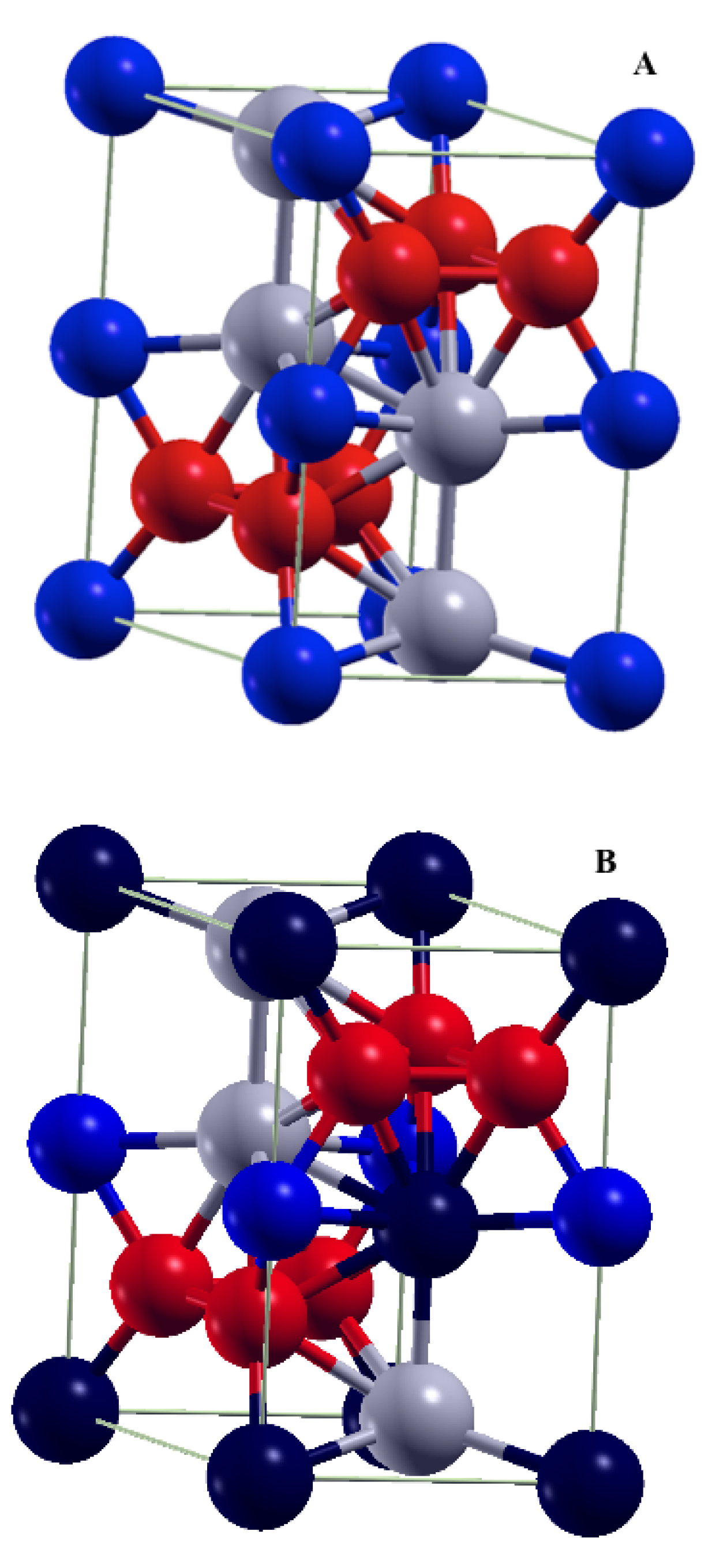
2.1. Hexagonal FeHf
2.2. Fe–Hf–Sb Alloy
3. Discussion
4. Conclusions
Author Contributions
Funding
Conflicts of Interest
Appendix A

| Group | Sb Substitution Sites | (eV/f.u) |
|---|---|---|
| 1 | [Fe(1)–Hf(1)] | 0 |
| [Fe(2)–Hf(2)] | 0 | |
| [Fe(2)–Hf(3)] | 0 | |
| [Fe(1)–Hf(4)] | 0 | |
| 2 | [Fe(3)–Hf(1)] | 0.137 |
| [Fe(4)–Hf(1)] | 0.137 | |
| [Fe(7)–Hf(1)] | 0.137 | |
| [Fe(5)–Hf(2)] | 0.137 | |
| [Fe(6)–Hf(2)] | 0.137 | |
| [Fe(8)–Hf(2)] | 0.137 | |
| [Fe(3)–Hf(3)] | 0.137 | |
| [Fe(4)–Hf(3)] | 0.137 | |
| [Fe(7)–Hf(3)] | 0.137 | |
| [Fe(5)–Hf(4)] | 0.137 | |
| [Fe(6)–Hf(4)] | 0.137 | |
| [Fe(8)–Hf(4)] | 0.137 | |
| 3 | [Fe(5)–Hf(1)] | 0.215 |
| [Fe(6)–Hf(1)] | 0.215 | |
| [Fe(8)–Hf(1)] | 0.215 | |
| [Fe(3)–Hf(2)] | 0.215 | |
| [Fe(4)–Hf(2)] | 0.215 | |
| [Fe(7)–Hf(2)] | 0.215 | |
| [Fe(5)–Hf(3)] | 0.215 | |
| [Fe(6)–Hf(3)] | 0.215 | |
| [Fe(8)–Hf(3)] | 0.215 | |
| [Fe(3)–Hf(4)] | 0.215 | |
| [Fe(4)–Hf(4)] | 0.215 | |
| [Fe(7)–Hf(4)] | 0.215 | |
| 4 | [Fe(2)–Hf(1)] | 0.258 |
| [Fe(1)–Hf(2)] | 0.258 | |
| [Fe(1)–Hf(3)] | 0.258 | |
| [Fe(2)–Hf(4)] | 0.258 |
References
- Skomski, R.; Coey, J.M.D. Permanent Magnetism; Institute of Physics: Bristol, UK, 1999. [Google Scholar]
- Gutfleisch, O.; Willard, M.; Bruck, E.; Chen, C.; Sankar, S.; Liu, J. Magnetic Materials and Devices for the 21st Century: Stronger, Lighter, and More Energy Efficient. Adv. Mater. 2011, 23, 821–842. [Google Scholar] [CrossRef] [PubMed]
- Skokov, K.P.; Gutfleisch, O. Heavy rare earth free, free rare earth and rare earth free magnets-Vision and reality. Scr. Mater. 2018, 154, 289. [Google Scholar] [CrossRef]
- Herbst, J.M. R2Fe14B Materials-Intrinsic Properties and Technological Applications. Rev. Mod. Phys. 1991, 63, 819. [Google Scholar] [CrossRef]
- Kumar, K. RETM5 and RE2TM17 Permanent Magnets Development. J. Appl. Phys. 1988, 63, R13. [Google Scholar] [CrossRef]
- Zhang, H.; Dirba, I.; Helbig, T.; Alff, L.; Gutfleisch, O. Engineering perpendicular magnetic anisotropy in Fe via interstitial nitrogenation: N choose K. APL Mater. 2016, 4, 116104. [Google Scholar] [CrossRef] [Green Version]
- Coey, J.M.D.; Sun, H. Improved magnetic properties by treatment of iron-based rare earth intermetallic compounds in ammonia. J. Magn. Magn. Mater. 1990, 87, L251. [Google Scholar] [CrossRef]
- Vekilova, O.Y.; Fayyazi, B.; Skokov, K.P.; Gutfleisch, O.; Echevarria-Bonet, C.; Barandiaron, J.M.; Kovacs, A.; Fischbacher, J.; Schrefl, T.; Eriksson, O.; et al. Tuning the magnetocrystalline anisotropy of Fe3Sn by alloying. Phys. Rev. B 2019, 99, 024421. [Google Scholar] [CrossRef] [Green Version]
- Goll, D.; Gross, T.; Loeffler, R.; Pflanz, U.; Vogel, T.; Kopp, A.; Grubesa, T.; Schneider, G. Hard Magnetic Off-Stoichiometric (Fe,Sb)2+xHf1−x Intermetallic Phase. Phys. Status Solidi RRL 2017, 11, 1700184. [Google Scholar] [CrossRef]
- Engdahl, G. Handbook of Giant Magnetostrictive Materials; Engdahl, G., Ed.; Academic Press: San-Diego, CA, USA, 2000; Volume 264. [Google Scholar]
- Levy, O.; Hard, G.L.W.; Curtarolo, S. Hafnium binary alloys from experiments and first principles. Acta Mater. 2010, 58, 2887. [Google Scholar] [CrossRef] [Green Version]
- Villars, P.; Berndt, M.; Brandenburg, K.; Cenzual, K.; Daams, J.; Hulliger, F.; Massalski, T.; Okamoto, H.; Osaki, K.; Prince, A.; et al. The Pauling File. J. Alloys Compd. 2004, 367, 293. [Google Scholar] [CrossRef]
- Kresse, G.; Joubert, D. From ultrasoft pseudopotentials to the projector augmented-wave method. Phys. Rev. B 1999, 59, 1758. [Google Scholar] [CrossRef]
- Wimmer, E.; Krakauer, H.; Weinert, M.; Freeman, A.J. Full-potential self-consistent linearized-augmented-plane-wave method for calculating the electronic structure of molecules and surfaces: O2 molecule. Phys. Rev. B 1981, 24, 864. [Google Scholar] [CrossRef]
- Ruban, A.V.; Skriver, H.L. Calculated surface segregation in transition metal alloys. Comput. Mater. Sci. 1999, 15, 119. [Google Scholar] [CrossRef]
- Buschow, K.H.J.; van Engen, P.G.; Jongebreur, R. Magneto-optical properties of metallic ferromagnetic materials. J. Magn. Magn. Mater. 1983, 38, 1. [Google Scholar] [CrossRef]
- Liechtenstein, A.I.; Katsnelson, M.I.; Antropov, V.P.; Gubanov, V.A. Local spin density functional approach to the theory of exchange interactions in ferromagnetic metals and alloys. J. Magn. Magn. Mater. 1987, 67, 65. [Google Scholar] [CrossRef]
- Ruban, A.V.; Simak, S.I.; Shallcross, S.; Skriver, H.L. Local lattice relaxations in random metallic alloys: Effective tetrahedron model and supercell approach. Phys. Rev. B 2003, 67, 214302. [Google Scholar] [CrossRef] [Green Version]
- Gyorffy, B.L.; Pindor, A.J.; Staunton, J.; Stocks, G.M.; Winter, H. A first-principles theory of ferromagnetic phase transitions in metals. J. Phys. F Met. Phys. 1985, 15, 1337. [Google Scholar] [CrossRef]
- Khmelevskyi, S.; Ruban, A.V.; Mohn, P. Magnetic ordering and exchange interactions in structural modifications of Mn3Ga alloys: Interplay of frustration, atomic order, and off-stoichiometry. Phys. Rev. B 2016, 93, 184404. [Google Scholar] [CrossRef] [Green Version]
- Shick, A.B.; Novikov, L.D.; Freeman, J.A. Relativistic spin-polarized theory of magnetoelastic coupling and magnetic anisotropy strain dependence: Application to Co/Cu (001). Phys. Rev. B 1997, 56, R14259. [Google Scholar] [CrossRef]
- Bruno, P. Tight-binding approach to the orbital magnetic moment and magnetocrystalline anisotropy of transition-metal monolayers. Phys. Rev. B 1989, 39, 865. [Google Scholar] [CrossRef] [Green Version]
- Shick, A.B.; Maca, F.; Masek, J.; Jungwirth, T. Prospect for room temperature tunneling anisotropic magnetoresistance effect: Density of states anisotropies in CoPt systems. Phys. Rev. B 2006, 73, 024418. [Google Scholar] [CrossRef] [Green Version]
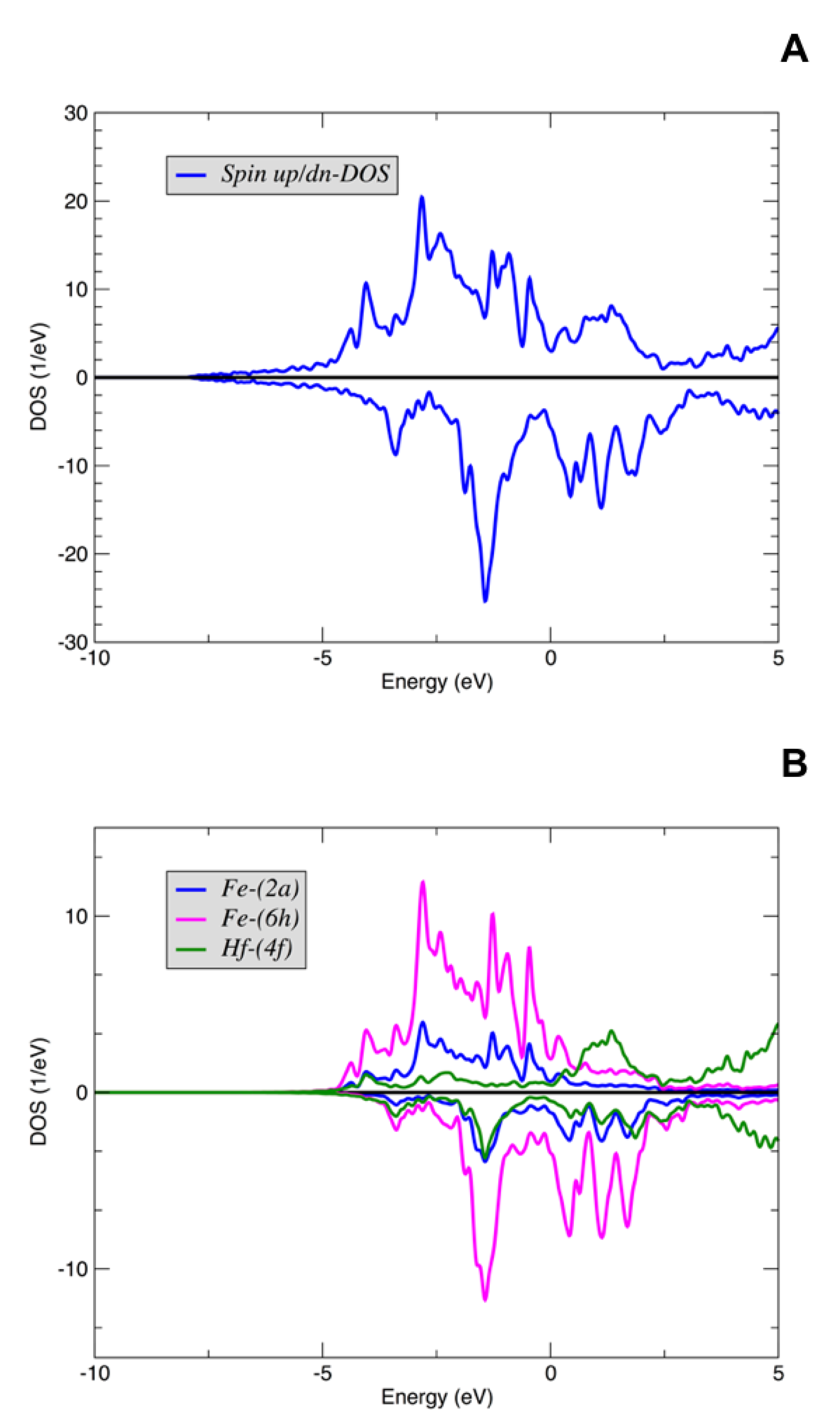

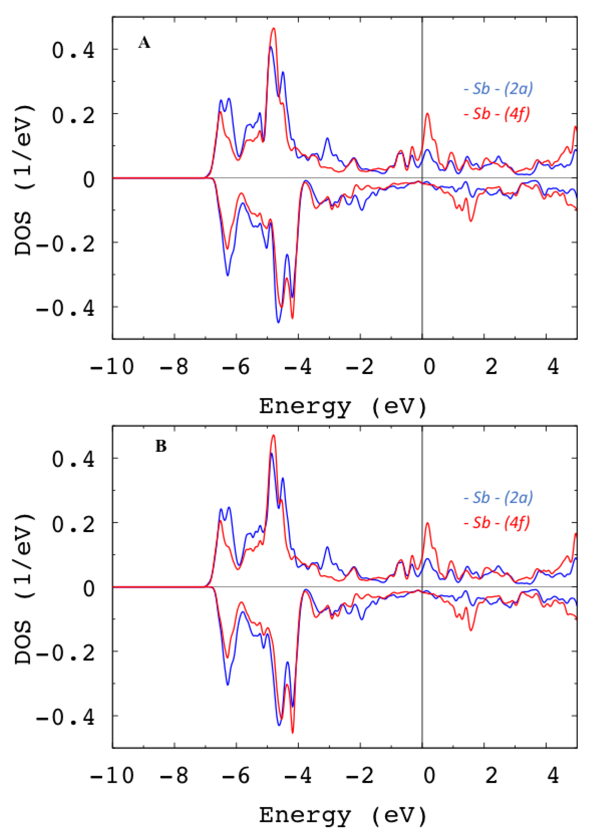
| FeHf | Fe58-Hf25-Sb17 | ||||
|---|---|---|---|---|---|
| Wyckoff | Element | Internal | Magnetic Moments | Element | Magnetic Moments |
| Positions | Position | ||||
| (2a) | Fe (1) | (0, 0, 0) | 1.71 | Sb | −0.03 |
| (2a) | Fe (2) | (0, 0, 1/2) | 1.71 | Fe | 2.00 |
| (6h) | Fe (3) | (0.17, 0.34, 1/4) | 1.74 | Fe | 1.64 |
| (6h) | Fe (4) | (− 0.34, −0.17, 1/4) | 1.74 | Fe | 1.64 |
| (6h) | Fe (5) | (−0.17, −0.34, −1/4) | 1.74 | Fe | 1.55 |
| (6h) | Fe (6) | (0.34, 0.17, −1/4) | 1.74 | Fe | 1.55 |
| (6h) | Fe (7) | (0.17, −0.17, 1/4) | 1.74 | Fe | 1.64 |
| (6h) | Fe (8) | (−0.17, 0.17, −1/4) | 1.74 | Fe | 1.55 |
| (4f) | Hf (1) | (1/3, 2/3, 0.563) | −0.35 | Hf | −0.28 |
| (4f) | Hf (2) | (2/3, 1/3, 0.063) | −0.35 | Hf | −0.30 |
| (4f) | Hf (3) | (1/3, 2/3, −0.063) | −0.35 | Hf | −0.27 |
| (4f) | Hf (4) | (2/3, 1/3, −0.563) | −0.35 | Sb | 0.01 |
| Total magnetic moment | 13.48 | 10.48 | |||
| Composition | MAE | ||
|---|---|---|---|
| unrelaxed Fe2Hf | 0.72 | −0.54 | |
| unrelaxed Fe58-Hf25-Sb17 | 0.55 | +0.82 | |
| relaxed Fe58-Hf25-Sb17 | 0.57 | +1.27 | |
| exp. Fe60-Hf26.5-Sb13.5 | 0.56–0.80 | 1.4–1.5 |
© 2020 by the authors. Licensee MDPI, Basel, Switzerland. This article is an open access article distributed under the terms and conditions of the Creative Commons Attribution (CC BY) license (http://creativecommons.org/licenses/by/4.0/).
Share and Cite
Kyvala, L.; Tchaplianka, M.; Shick, A.B.; Khmelevskyi, S.; Legut, D. Large Uniaxial Magnetic Anisotropy of Hexagonal Fe-Hf-Sb Alloys. Crystals 2020, 10, 430. https://doi.org/10.3390/cryst10060430
Kyvala L, Tchaplianka M, Shick AB, Khmelevskyi S, Legut D. Large Uniaxial Magnetic Anisotropy of Hexagonal Fe-Hf-Sb Alloys. Crystals. 2020; 10(6):430. https://doi.org/10.3390/cryst10060430
Chicago/Turabian StyleKyvala, Lukas, Maxim Tchaplianka, Alexander B. Shick, Sergii Khmelevskyi, and Dominik Legut. 2020. "Large Uniaxial Magnetic Anisotropy of Hexagonal Fe-Hf-Sb Alloys" Crystals 10, no. 6: 430. https://doi.org/10.3390/cryst10060430
APA StyleKyvala, L., Tchaplianka, M., Shick, A. B., Khmelevskyi, S., & Legut, D. (2020). Large Uniaxial Magnetic Anisotropy of Hexagonal Fe-Hf-Sb Alloys. Crystals, 10(6), 430. https://doi.org/10.3390/cryst10060430