1. Introduction
Topological defects (TDs) [
1] correspond to localized regions within ordered media where the relevant order parameter field is frustrated and topologically protected. In most cases, at the defect origin, the continuum field, which describes defectless equilibrium configurations, is not uniquely defined [
2]. In general, TDs appear as a consequence of the universal concept of broken symmetry and are of interest in all branches of physics [
1,
3]. The key topological feature of a topological defect is fingerprinted in its topological charge [
1,
2], which is a conserved quantity. Corresponding topological charge conservation laws regulate transformations (decomposing, merging, depinning) of defect configurations.
Owing to their topological origin, the physics of TDs exhibits several universal features. Consequently, it is of interest to find physical systems in which TDs are relatively easily experimentally formed, manipulated, and observed, which allows detailed and controlled analysis of the behavior of interest. For example, in the last decades, several studies analyzed quench driven coarsening of TDs in different condensed matter systems to gain information on structural details in the early universe [
3,
4,
5]. Condensed systems allow systematic and controlled experimental analysis, while related phenomena of the universe could be only indirectly and passively observed.
Nematic liquid crystals (NLC) [
6] offer an ideal testbed to study TDs [
7,
8,
9,
10] due to their unique combination of liquid behavior, softness, experimentally-tractable characteristic scales of time and spatial responses, and optical anisotropy. Furthermore, NLC structures possessing TDs could be exploited in various (in particular electro-optical) applications [
11,
12]. The uniaxial nematic structure is commonly described by the mesoscopic nematic director field
, which points along the local uniaxial NLC order, and the states
are physically equivalent (the so-called head-to-tail invariance) [
7]. In bulk, nematic equilibrium
is homogeneously aligned along a symmetry breaking direction. Several studies have been performed on thin LC films, in which relatively simple quasi-two-dimensional (2D) behavior [
13,
14,
15,
16,
17] is observed. Despite the simplicity, such systems display rich and complex behavior, in particular with respect to topological defect transformations. In 2D NLCs, only point defects exist. The role of topological charge is played by the winding number
m [
7] (also referred to as the Frank index). It determines the total rotation of
on encircling the defect core counterclockwise. Due to the head-to-tail invariance,
m can possess half-integer and whole integer numbers. Some typical TDs are shown in
Figure 1. TDs bearing positive and negative
m are commonly referred to as
defects and
antidefects, respectively, and pairs
in general tend to annihilate into a defectless configuration.
In general, high values of m are rarely realized. Namely, the free energy costs of a defect scales with
m2 [
16]. Consequently, if one enforces locally a defect bearing
, it tends to decompose [
16,
17,
18] to elementary defects bearing
, where the charge conservation law is obeyed. Note that the core structure of single
disclination is well known. In terms of the tensor nematic order parameter it was originally determined by Schopohl and Sluckin [
13]. Typical structural changes by traversing the defect core are shown in
Figure 2. The orientational frustration is resolved via the order reconstruction (OR) mechanism [
19]. In general, this mechanism is realized in cases where a relatively large orientational mismatch in nematic order is imposed on a scale comparable [
19,
20,
21,
22,
23] to the nematic biaxial order parameter relaxation length
The latter is relatively weakly temperature-dependent and is of order a few tens of nanometer [
23]. The presence of the order reconstruction (OR) mechanism within the core was confirmed experimentally [
24] in lyotropic chromonic LCs. Namely, such LCs exhibit a micron-scale nematic biaxial order parameter correlation length
that provides experimental insight into the core structure, whose characteristic linear size is comparable to
In this paper, we focus on the annihilation of surface enforced relatively highly charged {defect, antidefect} pair bearing the winding number in an effectively 2D nematic cell confinement. We enforce the annihilation via different routes: (i) by changing effective elastic LC properties, or (ii) by increasing an external in-plane electric field strength. We demonstrate that annihilation proceeds via two qualitatively different channels, whose realization is rather counterintuitive.
2. Methods
We use the Landau-de Gennes mesoscopic approach in terms of the traceless and symmetric tensor nematic order parameter
[
6]. In its eigen frame, it is expressed as [
20]
where
and
stand for
eigenvalues and eigenvectors, respectively. Uniaxial states are commonly described by [
6]
The nematic uniaxial order parameter quantifies the extent of fluctuations about the local nematic director , and () reflects “prolate” (“oblate”) shape in the ellipsoidal presentation of the LC mesoscopic order. We henceforth refer to such configurations as positive uniaxial and negative uniaxial nematics.
Biaxial states could be assessed if elastic distortions are present. The degree of biaxiality is well measured by the biaxiality parameter [
25]
The limiting values and correspond to a uniaxial nematic state and a nematic order exhibiting the maximal biaxiality, respectively.
The eigenvalues can be parametrized as
where
Note that the eigenvalues {
} can be expressed using two independent variables (i.e., {s,
}) due to the constraint
. The (
s,
)
order parameter space is shown in
Figure 2b. The isotropic order is reflected by
. Nematic configurations corresponding to
,
and
exhibit positive uniaxial states along
and
respectively. States
,
and
correspond to the negative uniaxial states along
and
The remaining states are biaxial. In this parametrization it holds
. Any continuous change in nematic order is fingerprinted in a continuous change in the
order parameter space.
In our study we will consider nematic structures in the Cartesian coordinate system (
x,y,z), whose coordinate unit vectors are given by the triad (
,
,
). Of interest are quasi-two-dimensional structures, where the
Q eigenvector along the
z-axis remains fixed (i.e.,
). In this case, in addition to {s,
}, only one additional parameter (i.e. an angle
) is needed to determine
Q, describing the rotation of the
Q eigenframe with respect to the Cartesian frame:
Presentation of
Q in terms of {
s,
} is useful to illustrate or guess different possible
Q configuration variations along a given path in real space connecting two sites imposing different nematic order. An example is illustrated in
Figure 2, where one crosses the core of
defect.
However, this
Q representation does not provide a one-to-one mapping of each component (is not injective) [
26]. For this reason, we used in simulations parametrization given by
in terms of variational fields {
}. It holds
,
, and
Note that the exchange of eigenvalues [
13] between
and
corresponds to the condition
It was originally introduced to describe the elastic deformation within the core structure of
wedge defects [
13]. The basic mechanism enabling this transformation is commonly referred to as order reconstruction [
12,
19].
2.1. Free Energy
We express the free energy
F of a confined LC as a sum of nematic condensation (
), elastic
, external electric field
, and surface (
free energy density contributions:
Here
and
stand for the volume and area measures, and the superscript
(i) refers to the i-th confining substrate. The free energy densities are expressed using the standard Landau-de Gennes expansion [
6] in
We take into account only the most essential symmetry allowed contributions to illustrate phenomena of interest [
6,
20,
27]:
Here
are positive material-dependent constants,
stands for the isotropic supercooling temperature,
is a positive representative nematic elastic constant (i.e., we use the single elastic constant approximation),
stands for an external electric field,
is the dielectric anisotropy (we limit to materials with
),
> 0 is the anchoring strength coefficient at the i-th confining surface, which enforces nematic order described by
[
27].
2.2. Geometry of the Problem
We study nematic configurations inside a three-dimensional well with square cross section of length
R and thickness
h<<R. The geometry of the problem is depicted in
Figure 3, where we use Cartesian coordinate system (
x,y,z). At the lateral walls (
Figure 3a) we enforce strong uniaxial tangential anchoring conditions:
At the bottom (command) plate we enforce the nematic pattern consisting of a pair {
defect, antidefect} of strength {
} placed at (
) and (
):
Typically, we set The opposite plate enforces degenerate tangential anchoring.
This setup mimics samples that could be realized experimentally using, for instance, the atomic force microscope (AFM) scribing method [
28]. In a typical experimental setup, a nematic LC is confined within a thin plane-parallel cell, where at least one (command) surface imposes anchoring conditions inscribed via an AFM stylus [
28], while the opposing surface imposes a degenerate tangential anchoring. Furthermore, in some simulations we switch on a spatially homogeneous electric field
along the
y-axis.
In simulations, we assume that the cell is thin enough so that the nematic structure is effectively two dimensional, exhibiting only variations in the (
x,y) plane. Consequently, we use in numerical simulation the parametrization for the nematic tensor order parameter [
22] given by Equation (7), where
and
are the variational parameters. In this parametrisation
is always an eigenvector of
.
For presentational purposes, we introduce the dimensionless temperature
and material characteristic lengths [
20]:
The quantity
stands for the external field nematic extrapolation length, which we express at the superheating temperature
,
is the biaxial correlation length,
is the surface extrapolation length,
w stands for the anchoring strength imposed by the command surface, and
stands for the superheating bulk value of
S. We henceforth utilize the relative anchoring strength of the command surface plate and of the external field
=
Ein terms of dimensionless ratios, respectively.
We minimize the free energy of the system with respect to the variational parameters
and
. The resulting Euler-Lagrange equations are solved numerically using the standard over-relaxation method. Technical and numerical details are given in [
29].
3. Results
Of interest are different paths in which annihilation of a master surface anchoring enforced pair {
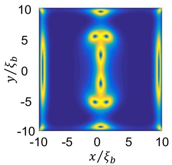
} annihilates in the geometry and boundary conditions described in the Methods section. The initial nematic configuration is shown in
Figure 4a (biaxiality pattern) and
Figure 5a (director field pattern). Each of the command surface imposed
defects at
decay in three elementary
daughter defects. Due to boundary conditions, two additional defects
and
at the top and the bottom boundaries of
Figure 4a, respectively, are introduced. In addition, at the lateral boundaries, relatively (non-singular) strongly elastically deformed regions exist, which are fingerprinted by relatively strong local biaxiality. Furthermore, sharp corners of their structure enforce
type surface distortions [
30].
For latter convenience, we label the three positively charged daughter defects (emerging from
) by P1, P2, P3, and the corresponding negatively charged daughter defects (emerging from
) by N1, N2, N3 as shown in
Figure 4a. Boundary condition generated defects are labeled by P4 (upper boundary) and N4 (bottom boundary). Furthermore, at some stages at lateral boundaries, elastic distortions are strong enough to trigger nucleation of creations of pairs {
defect, antidefect}, see
Figure 4c. We label these defect pairs by (N5,P5) and (N6,P6).
First, we enforce the annihilation by gradually decreasing the relative importance of the surface anchoring field. In practice, this could be achieved by decreasing temperature towards the second-order nematic-SmA phase transition temperature
, which is accompanied by divergence [
6] in the nematic twist and bend elastic constants. The relative importance of elastic and surface penalties of a confined NLC is measured by the ratio
where
R stands for the characteristic confinement length, and
is the representative Frank nematic elastic constant, and
W measures the dimensional anchoring strength. In our simulations this ratio is measured by
. Therefore, on approaching
, the ratio
would decrease. The limit
corresponds to the strong anchoring regime, while
corresponds to weak anchoring. The initial configuration, shown in
Figure 4a, is evaluated for
which is strong enough to prevent the annihilation of {3/2,-3/2} pair; however, weak enough to allow decomposition of
singularities. Such conditions are realized in typical samples prepared using AFM scribing method [
17].
On decreasing
, in the first stage, the closest oppositely charged daughter defects (N1,P1) begin to approach (see
Supplementary movie Annihilation 1) until they mutually annihilate (See
Figure 4b). Then the defect pairs (N2,P4), (P2,N4), and afterward (P3,N3) annihilate. During these processes, rearrangement of defects imposes sufficiently strong elastic distortions at the lateral boundaries to trigger the formation and depinning of two pairs of defects (P5,N5) and (P6,N6), as shown in
Figure 4c. Finally, these defects are adsorbed by sharp edges of the confining boundary. Consequently, the winding number, characterizing strong distortions in corners, revert their winding number. This is evidently shown in
Figure 5c,d, where one observes
winding number transformations of the director field profiles within the edges.
Next, we trigger annihilation by applying and gradually increasing a spatially homogeneous external electric field
. The initial configuration for
E = 0 is shown in
Figure 6a, where we set
On increasing
(see
Supplementary movie Annihilation 2), in the first stage, the inner (N1,P1) defect approach and finally annihilate (
Figure 6c). The remaining defects annihilate in a qualitatively different way compared to the process shown in
Figure 4, where lateral defect pairs (N5,P5) and (N6,P6) are strongly involved. Namely, the oppositely charged daughter and lateral defects approach each other and finally annihilate (
Figure 6d). Furthermore, initially localized
structures of P4 and P5, clearly visible in
Figure 6a–e, transform to nonlocalized order reconstruction planes. This defect core “explosion” was studied in detail in [
31]. Here we summarize the key stages of the process. In this
E-driven transformation, the initially spherically shaped biaxial core of a defect begins to grow as it is pushed towards a limiting wall (in our setting
y =
R/2 boundary for P4, and
y = −
R/2 boundary for M4) on increasing
E. For
E > 0, the ellipsoidal core-shape becomes progressively elongated along the
x-axis. At some critical value of
E, the core diverges (i.e., its longest linear size equals
R), and a planar order reconstruction plane is formed. In this case order reconstruction takes form near the bottom and top confining plate. The corresponding nematic director profile, reflecting the
Q eigen frame orientation, is shown
Figure 7b. Note that on crossing the OR plane the LC molecules experience a mesoscopic shape transformation, similar to the one shown in
Figure 2c along the direction 1-5. The OR plane is formed at
, which for typical LCs [
6] corresponds to
V/m.
4. Discussion
We studied numerically the annihilation of master surface enforced highly charged pair {defect, antidefect}, bearing topological charges
. A Landau-de Gennes mesoscopic approach in terms of the tensor nematic order parameter was used. We assumed quasi-two-dimensional order, which in practice is sensible for relatively thin nematic cells. We chose geometrical setups and boundary conditions that could be realized experimentally in future work. For example, highly charged defect structures could be enforced using, e.g., the Atomic Force Measurement scribing method [
30], or plasmonic photoalignment technique [
32]. In simulations we enforce a pair of
defects via the command surface scribed pattern. We used anchoring strength coefficients that are strong enough to prevent annihilation of the pair, however weak enough to allow decomposition [
33] of each surface pattern favored
defect into three daughter elementary defects bearing
Furthermore, we confined the pair in a rectangular confinement region. One would expect mutual annihilation of the two daughter assemblies on varying relevant control parameters. However, the chosen setup enabled a nontrivial annihilation scenario of TDs, also involving creation of additional defects, absorption of TDs within edges of the confining substrate, and one dimensional “explosion” of defect cores. We illustrate two qualitatively different annihilation channels, either by progressively weakening the relative importance of the surface anchoring field or increasing external in-plane electric field. Both processes could be realized experimentally by using relatively simple experimental setups. In our setting, the reference structures exhibit eight elementary TDs, where two additional defects are introduced by the rectangular confinement. In the anchoring weakening-driven annihilation, only four daughter defects were mutually annihilated, and the remaining two were annihilated with confinement enabled TDs. On the contrary, in
E-driven annihilation only one pair of daughter defects were mutually annihilated and the remaining four defects were annihilated via TDs, which were created via creation and depinning of additional pairs
{defect, antidefect}.Note that in realistic LC samples the characteristic nematic elastic constants are different from each other. Nematic elasticity is commonly expressed in terms of splay (
, twist (
, bend (
, and saddle-splay (
elastic constants, introduced in the Frank-Oseen uniaxial description [
34]. In our geometry the elastic distortions involving twist and saddle-splay deformations are absent. Therefore, only
and
are expected to make an impact on defect structures. In conventional LCs it holds
In this case the defect rearrangement would be carried out via LC structural variations that prefer the splay nematic deformation. Furthermore, this elastic anisotropy would break the mirror symmetry along the y-axis observed in
Figure 4a. Namely, the core structures of
and
defects would be different, because the relative contributions of bend and splay deformations are different in these defects.
On approaching a second order N-SmA phase transition
diverges, whereas
remains finite. Because any arrangement of TDs in our study involves bend elastic distortions, TDs would annihilate on increasing
This elastic anisotropy would, for sure, at least quantitatively influence the annihilation scenario. The defect rearrangement would be realized via LC rearrangements preferring the splay deformation. However, for our scenario we do not expect a qualitatively different rearrangement of TDs from those presented in
Figure 4 and
Figure 6.
Nevertheless, it is a demanding task to obtain a numerically “realistic” result of elastic anisotropy on rearrangement of TDs. In this paper we work in the approximation of equal elastic constants, represented by a temperature independent constant
L. In reality, several different elastic constants would appear, which determine the relative importance of different symmetry-allowed elastic contributions expressed in terms of
Q and its spatial derivatives. For example, in Cartesian coordinates (
x,y,z) = (
), the expansion up to the 2nd order in
Q is commonly expressed as [
35,
36]
Here we use the summation convention over repeated indices, commas indicate spatial derivatives (e.g.,
), and the superscript (2) in
indicates the 2
nd order expansion contributions in the elastic free energy density. Far from defect cores, the constants
-
could be mapped to the more familiar Frank elastic constants. However, for the expansion up to the 2
nd order in
Q it holds that
[
35,
36], while in most LCs these constants can be significantly different. Higher order terms need to be added [
35,
36] to lift this degeneracy, for example
However, according to recent studies in lyotropic chromonic LCs [
24], even taking into account the above mentioned elastic anisotropy, one could not exactly reproduce experimentally the observed core structures of
TDs. Therefore, current theoretical modeling does not correctly describe cores of single
TDs, and the core structure details might influence annihilation scenarios. For this reason, we performed our study at the proof-of-principle level.
In our selected geometry pairs of defects {−1/2,1/2} are typically created as an intermediate step and they actively mediate external stimulus driven annihilation processes. To estimate the free energy costs of a pair {−1/2,1/2} creation we use the Lyuksyutov constraint [
26,
37] in which the cubic term in
is neglected. This is sensible approximation for LCs exhibiting weakly first order I-N phase transition. With this in mind, it follows
, where
is minimized in the nematic phase for
corresponding to
The main penalty of introducing a defect is “melting” of LC order within the core of TDs. Note that for a pair {−1/2,1/2}, the nematic director in the far field is spatially homogeneous because the total charge of the pair equals to zero. The free energy cost of introducing a single
defect of length
h is roughly
where
estimates the defect core volume. For a typical nematic LC it holds that
nm [
23]. Therefore, deep in the nematic phase it costs roughly
to create a pair of defects, where we take
K,
,
K, and
is the Boltzmann constant.


