Article

Exploration of Aluminum and Titanium Alloys in the Stream-Wise and Secondary Flow Directions Comprising the Significant Impacts of Magnetohydrodynamic and Hybrid Nanofluid

1
Department of Mathematics, College of Arts and Sciences, Prince Sattam bin Abdulaziz University, Wadi Aldawaser 11991, Saudi Arabia
2
Department of Mathematics and Social Sciences, Sukkur IBA University, Sukkur 65200, Pakistan
3
Department of Mathematic, The Begum Nusrat Bhutto Women University, Sukkur 65170, Pakistan
4
Department of Mathematical Sciences, Federal Urdu University of Arts, Science & Technology, Gulshan-e-Iqbal, Karachi 75300, Pakistan
5
Faculty of Mathematics and Statistics, Ton Duc Thang University, Ho Chi Minh City 72915, Vietnam
6
Department of Mathematics, Cankaya University, Ankara 06790, Turkey
7
Institute of Space Sciences, 077125 Magurele-Bucharest, Romania
8
Department of Medical Research, China Medical University Hospital, China Medical University, Taichung 40447, Taiwan
*
Author to whom correspondence should be addressed.
Crystals 2020, 10(8), 679; https://doi.org/10.3390/cryst10080679
Submission received: 16 June 2020 / Revised: 31 July 2020 / Accepted: 2 August 2020 / Published: 6 August 2020
(This article belongs to the Section Inorganic Crystalline Materials)

Abstract

:
This exploration examines the nonlinear effect of radiation on magnet flow consisting of hybrid alloy nanoparticles in the way of stream-wise and cross flow. Many experimental, as well as theoretical explorations, demonstrated that the thermal conductivity of the regular liquid increases by up to 15 to 40% when nanomaterials are mixed with the regular liquid. This change of the thermal conductivity of the nanoliquid depends on the various characteristics of the mixed nanomaterials like the size of the nanoparticles, the agglomeration of the particles, the volume fraction, etc. Researchers have used numerous nanoparticles. However, we selected water-based aluminum alloy (AA7075) and titanium alloy (Ti6Al4V) hybrid nanomaterials. This condition was mathematically modeled by capturing the Soret and Dufour impacts. The similarity method was exercised to change the partial differential equations (PDEs) into nonlinear ordinary differential equations (ODEs). Such nonlinear ODEs were worked out numerically via the bvp4c solver. The influences of varying the parameters on the concentration, temperature, and velocity area and the accompanying engineering quantities such as friction factor, mass, and heat transport rate were obtained and discussed using graphs. The velocity declines owing to nanoparticle volume fraction in the stream-wise and cross flow directions in the first result and augment in the second result, while the temperature and concentration upsurge in the first and second results. In addition, the Nusselt number augments due to the Soret number and declines due to the Dufour number in both results, whereas the Sherwood number uplifts due to the Dufour number and shrinks due to the Soret number in both results.

Graphical Abstract

1. Introduction

In recent times, numerous scientists and researchers have made significant efforts to offer different techniques to change the heat transfer rate owing to its incredible demand in applications in industry and processing. Consequently, the assignment of an enhanced heat transfer rate in common production equipment is a practical and novel advance for detailed assessment of the development of heat capabilities. This is commonly used in heat exchangers, microelectronics, nuclear reactors, bio-medicine, transportation, etc. A group of liquids with superior heat transfer characteristics was proposed by mixing some representative nanomaterials in the base liquids, such as ethylene-glycol, oil, and water. Choi [1] exploited nanoliquids for the first time by adding a diluted nanoparticle suspension to the base liquids. Khanafer et al. [2] considered a model to analyze the performance of heat transport of nanoliquids within an enclosure. Ali et al. [3] reported the experimental results of water based ZnO nanoparticles to change the behavior of the heat transport for the radiator of a car. Ghasemi and Aminossadati [4] considered the free convective flow through an inclined enclosure occupied with water based CuO nanoliquid. Ahmed and Pop [5] studied the influence of three distinct nanoparticles on mixed convective flow entrenched in a permeable medium. The characteristics of the drop of pressure and heat transfer ofTiO2 nanoparticles through a mini-channel heat sink were studied experimentally by Arshad and Ali [6]. They showed that the thermal behavior of TiO2 nanoparticles was strongly reliant on the power of heating, but at a lower power of heating, the heat transfer was more effective. Afterwards, numerous researchers [7,8,9,10,11,12,13,14] discussed the significance of nanoliquids from different viewpoints. Recently, Saffarian et al. [15] utilized nanofluid to change the heat transfer (HETR) of a solar collector through a flat surface via the shapes of several flow paths.
Despite the practical insights into nanofluids, there have been few types of nanofluids identified as hybrid nanofluids. Hybrid nanoparticles are developed due to their higher thermo-physical properties, as well as their rheological performance in conjunction with the increasing heat transport properties. Hybrid nanoliquids are developed with nanoparticles created from two separate nanomaterials suspended in a base liquid. This novel class of magnetized heat transport fluids has been studied by numerous researchers to discover solutions to real-life problems and has been broadly exploited in many (HETR) fields, like machine and generator cooling, drug delivery, refrigeration, biomedicine, etc. Sarkar et al. [16] explored the impact of hybrid nanoliquids by utilizing three distinct base liquids (water, ethylene glycol, and oil). According to their observations, a suitable method of hybridization might disrupt the thermal effectiveness of the hybrid nanoliquids. Furthermore, Sidik et al. [17] came to a similar conclusion: the thermal properties of the hybrid nanoliquid (HNAN) were superior to the nanoliquid and regular liquid alone. The thermo-physical properties, as well as the synthesis of a hybrid nanoliquid, were explored by Gupta et al. [18]. The types of host liquids (water, ethylene glycol, and oil) and the types of nanoparticles (metal oxides, metal, metal nitride, and carbon materials), their shape, and size were amongst the features that could affect the thermo-physical properties. Numerical, as well as analytical investigations of hybrid nanofluids were made by Huminic and Huminic [19]. Shah and Ali [20] utilized the fabrication technique along with the features of hybrid nanoliquids to investigate solar energy systems. They showed that the (HNANs) played a significant role in the augmentation of power production. A significant assessment of hybrid nanoliquids was presented by Baber et al. [21]. Recently, Qiu et al. [22] presented an exceptional review on the thermo-physical properties of nanofluids, as well as hybrid nanofluids.
Fourier’s law illustrates the relation between the temperature gradient and energy flux and is obtained through the correlation of the concentration gradient and mass flux. The Dufour or diffusion-thermo happened due to energy flux, which was posed via a composite gradient. Whereas, the Soret or thermal-diffusion is due to mass fluxes, which are generated by temperature gradient. In another manner, the Soret influence refers to species discrimination rising in an initial homogeneous mixture proposed to a thermal gradient and the Dufour impact submitted to heat-flux generated via a concentration gradient. The influence of the Dufour effect, as well as the Soret effect, in liquids with superior concentration and temperature gradients is highly critical. The physical insight into the liquid’s mechanics is also very critical. Such effects can be calculated in the areas of reactor protection, solar collectors, combustion flames, and building energy conservation. Prasad [23] discussed the impact of the electric field on the flow from a vertical surface in a non-Darcy medium through the influence of the Dufour and Soret effects. Pal and Mondal [24] explored the merged magnetic and radiation impacts on viscous mixed convective flow by a nonlinear stretched surface in a non-Darcy permeable medium with the influence of the Dufour and Soret effects. Makinde [25] studied the Soret effect on magneto hydrodynamic flow across a vertical solid surface with the Dufour number. Chamkha and Rashad [26] considered the unsteady flow along with the heat and mass transport through a rotated upright cone. They observed that the concentration and thermal fields were additionally influenced by the amount of the Dufour and Soret constraints. Zaib and Shafie [27] researched the impacts of viscous dissipation and chemical reactions on magneto flow from a stretched radiation sheet. Reddy and Chamkha [28] surveyed the combination of Dufour numbers and as well as Soret numbers on MHD flow comprised of water-based nanomaterials Al2O3 and TiO2 from a permeable stretched surface by heat generation and absorption. Dzulkifli et al. [29] discussed the time dependent flow comprised of water-based copper nanomaterial through a stretched/shrinking sheet with the Dufour, slip, and Soret effects, and performed a stability analysis. In recent times, Falodun and Idowu [30] used the spectral relaxation technique to discuss the Dufour non-Newtonian fluid and Soret numbers from a half-infinite plate.
Secondary or cross flow occurs when the boundary layer portion of the velocity is normal in the free-stream direction. The transverse motion in these flows is presumed to be fully developed. The effect of cross-flow can be seen in many engineering cases, including wind flow phenomena and mechanical aerospace. Jones [31] demonstrated appealing cross-flow solutions where he noticed the sweep-back effect on the boundary layer. He also reported that the coefficient of lift decreased while the laminar flow stable area increased. Weidman [32] proposed new results of cross flow for laminar boundary layers. He examined five distinct problems involving cross flow. The forced convection flow along with heat transport containing cross flow were explored by Bhattacharyya and Pop [33]. Dual results were found for some values of the moving constraint. Haq et al. [34] scrutinized the impact of viscous dissipation comprised of single, as well as multiple wall carbon nanotubes through the cross flow (CRF) and stream-wise (STWE) directions. Khan et al. [35] explored the chemical reaction and activation energy of Ti6Al4V alloy nanoparticles in the (CRF) and (STWE) directions.
The impacts of the Soret and Dufour effects in the (CRF) and (STWE) direction of nanofluids containing hybrid alloys have not been considered so far. Here, the single-phase model is considered in the presence of these effects. The alloy is a metallic solid or a liquid comprised of the grouping of homogenous and non-homogenous mixtures of two or more nanometer-sized metalloid particles. The alloy is used in many processes like hip joint replacement, surgical implantation, and several biological treatments. Thus, this is the impetus of existing works to analysis the impact of the Soret and Dufour numbers on magneto flow comprised of hybrid AA7075 and Ti6Al4Valloy nanoparticles through a cross flow with nonlinear radiation. The leading PDEs are modified to nonlinear ODEs via a similarity method. The transformed ODE system is then worked out via the built-in solver called bvp4c. The impacts of physical constraints on the flow field are portrayed.

2. Problem Formulation

Consider a 3D flow problem in the stream-wise direction together with cross flow comprised of AA7075 and Ti6Al4V hybrid alloy nanomaterials through a heated surface. The problem’s geometry is revealed in Figure 1. Furthermore, the impact of the Dufour and Soret effects along with nonlinear radiation are included. The uniform velocity of the moving surface is taken as λ U 0 in and out of the origin and is kept at x = 0 ; here, x is captured beside the surface, and U 0 and λ are the invariable velocity and moving constraint, respectively. The erratic field of the magnetic number proceeds as B = B 0 2 x and normal to the edge. The concentration and temperature, respectively, are calculated as C w and T w , while C and T represent the free-stream concentration and temperature. In addition, it is supposed that the extent of the range of secondary flow in the span-wise direction is broad and, thus, complete. As a consequence, the concentration, energy, and momentum equations are taken to be free of the z-coordinate. The leading governing equations, in the forms of PDEs by scaling the boundary layer approximation, are [33,34,35]:
v y + u x = 0 ,
v u y + u u x = μ ^ h b n f ρ ^ h b n f ( 2 u y 2 ) + σ ^ h b n f B 2 ρ ^ h b n f ( U 0 u ) ,
v w y + u w x = μ ^ h b n f ρ ^ h b n f ( 2 w y 2 ) + σ ^ h b n f B 2 ρ ^ h b n f ( w 0 w ) ,
v T y + u T x = α ^ h b n f 2 T y 2 1 ( ρ ^ c ^ p ) h b n f q r y + D m k T c s c ^ p 2 C y 2 ,
v C y + u C x = ( D m k T T m ) 2 T y 2 + D ^ h b n f 2 C y 2 ,
And through the boundary restrictions:
v = v w = v 0 ν f 2 x , u = λ U 0 , w = 0 , C = C w , T = T w   at   y = 0 , w w 0 , u U 0 , C C , T T   as   y .
In the aforementioned system of equations, v , w , and u are the components of velocity along the y-, z-, and x-axes, respectively.

2.1. Thermo-Physical Properties of the Hybrid Nanoliquid

The density, heat capacity, dynamic viscosity, thermal conductivity, electrical conductivity, and mass diffusiveness of the expression of hybrid nanoliquids are given in Table 1.
Exercising the Rosseland approximation, the radiative heat flux is known as q r , and its appearance is:
q r = ( 16 σ * T 3 3 k * ) T y .
As previously mentioned, T y stands for change of partial derivative with respect to the coordinate y . Further, k * and σ * represent the mean of the Rosseland coefficient and the Stefan–Boltzmann constant, respectively.
The similarity transformation is implemented as:
η = y ( U 0 2 x υ f ) 0.5 , ψ = f ( η ) ( 2 x U 0 υ f ) 0.5 , w = w 0 g ( η ) , ϕ ( η ) = C C C C w , θ ( η ) = T T T T w .
In the above similarity variables, the Greek symbol ψ stand for the stream function, and mathematically, it is expressed as { ψ x , ψ y } = { v , u } .
The implementation of the transformations above in Equations (2)–(6) is to obtain a consistent dimensional form of the ODEs via the well-known table equation (Calculation processes can be found in Appendix A) as follows:
f + β 1 { β 2 f f M β 3 ( f 1 ) } = 0 ,
g + β 1 { β 2 f g β 3 M ( g 1 ) } = 0 ,
θ [ ( θ ( θ w 1 ) + 1 ) 3 + 3 4 R d β 4 ] + 3 4 β 5 R d Pr ( f θ + D u ϕ ) + 3 ( θ w 1 ) ( θ ( θ w 1 ) + 1 ) 2 ( θ ) 2 = 0 ,
ϕ + β 6 { S c ( f ϕ + S r θ ) } = 0 .
The major boundary restriction in question is:
S = f ( 0 ) , g ( 0 ) = 0 , λ = f ( 0 ) , 1 = θ ( 0 ) , 1 = ϕ ( 0 ) , f ( ) 1 , g ( ) 1 , θ ( ) 0 , ϕ ( ) 0 .
in which:
β 1 = ( 1 ϕ 1 ) 2.5 ( 1 ϕ 2 ) 2.5 ,
β 2 = ( ( 1 ϕ 2 ) { ( 1 ϕ 1 ) + ϕ 1 ρ ^ s 1 ρ ^ f } + ϕ 2 ρ ^ s 2 ρ ^ f ) ,
β 3 = ( σ ^ s 2 ( 1 + 2 ϕ 2 ) + 2 σ ^ b f ( 1 ϕ 2 ) σ ^ s 2 ( 1 ϕ 2 ) + σ ^ b f ( 2 + ϕ 2 ) ) ( σ ^ s 1 ( 1 + 2 ϕ 1 ) + 2 σ ^ f ( 1 ϕ 1 ) σ ^ s 1 ( 1 ϕ 1 ) + σ ^ f ( 2 + ϕ 1 ) ) ,
β 4 = { k ^ s 2 + 2 k ^ nf 2 ϕ 2 ( k ^ n f k ^ s 2 ) k ^ s 2 + 2 k ^ nf + ϕ 2 ( k ^ n f k ^ s 2 ) } { k ^ s 1 + 2 k ^ f 2 ϕ 1 ( k ^ f k ^ s 1 ) k ^ s 1 + 2 k ^ f + ϕ 1 ( k ^ f k ^ s 1 ) } ,
β 5 = ( ( 1 ϕ 2 ) [ ϕ 1 ( ρ ^ c ^ p ) s 1 ( ρ ^ c ^ p ) f ] + ( 1 ϕ 1 ) + ϕ 2 ( ρ ^ c ^ p ) s 2 ( ρ ^ c ^ p ) f ) ,
β 6 = ( 1 ϕ 1 ) ( 1 ϕ 2 ) .
The proprietary, dimensionless parameters in Equations (9)–(13) are expressed in mathematical form as:
Pr = ν f α ^ f , M = σ ^ f B 0 2 ρ ^ f U 0 , R d = k * k ^ f 4 σ * T 3 , S c = ν f D ^ f , S = v 0 U 0 , D u = D m k T ( C w C ) ν f c s c ^ p ( T w T ) , S r = D m k T ( T w T ) ν f T m ( C w C ) .
where the above-mentioned constraints are known as the radiation ( R d ) , Prandtl ( Pr ) , magnetic ( M ) , suction/blowing ( S ) , Schmidt number ( S c ) , Soret ( S r ) , and Dufour numbers ( D u ) , respectively.

2.2. Skin Friction

The skin friction coefficient along the stream-wise and cross flow directions are signified as
C f x = μ ^ h b n f ( u y ) y = 0 ρ ^ f U 0 2 = μ ^ h b n f μ ^ f f ( 0 ) ( 2 Re x ) 1 / 2 ,
C f z = μ ^ h b n f ( w y ) y = 0 ρ ^ f w 0 2 = μ ^ h b n f μ ^ f g ( 0 ) ( 2 Re x ) 1 / 2 ( w 0 / U 0 ) .

2.3. Nusselt Number

The local Nusselt number is defined as and then simplified to the non-dimensional form as follows:
N u x = x [ ( k ^ h b n f T y ) y = 0 + ( q r ) w ] k ^ f ( T w T ) = k ^ h b n f k ^ f ( Re x / 2 ) 1 / 2 θ ( 0 ) { 1 + 4 3 R d ( 1 + θ ( 0 ) ( θ w 1 ) ) 3 } .

2.4. Sherwood Number

The local Sherwood number is described as and to write in the non-dimensional form as follows:
S h x = x ( D ^ h b n f C y ) y = 0 D ^ f ( C w C ) = D ^ h b n f D ^ f ( Re x / 2 ) 1 / 2 ϕ ( 0 ) ,
where the expression of the Reynolds number is Re x = x U 0 / ν f .

3. Results and Discussion

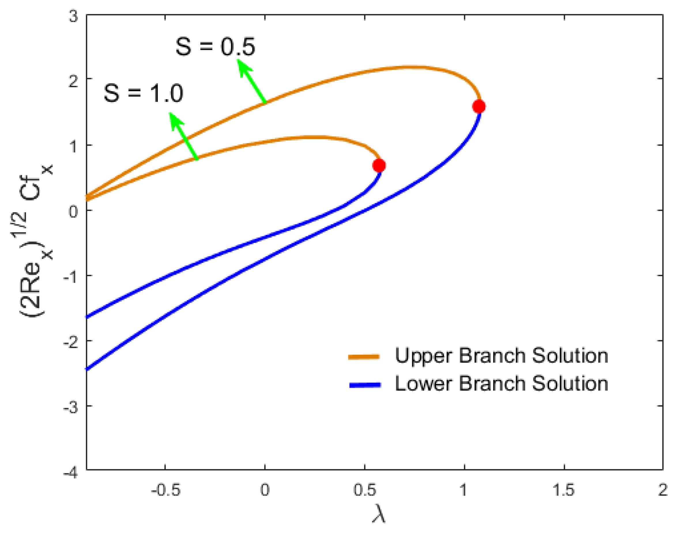
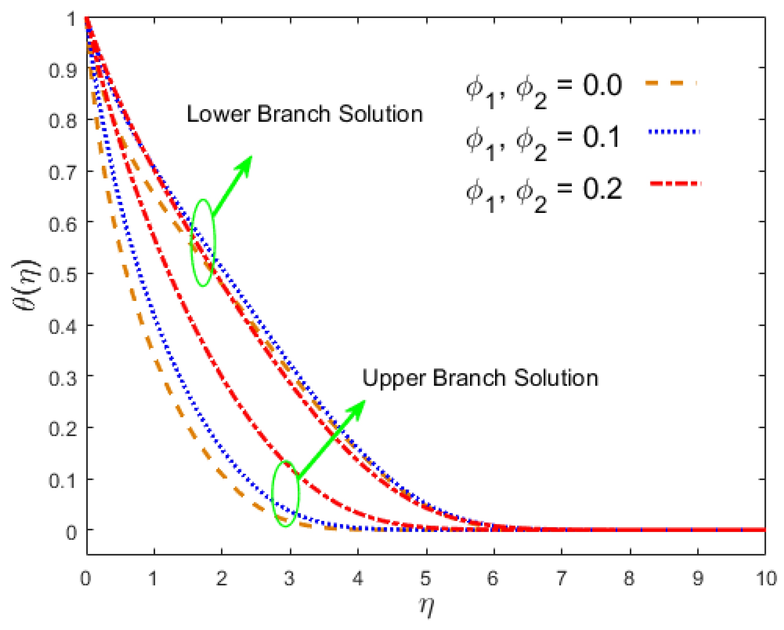
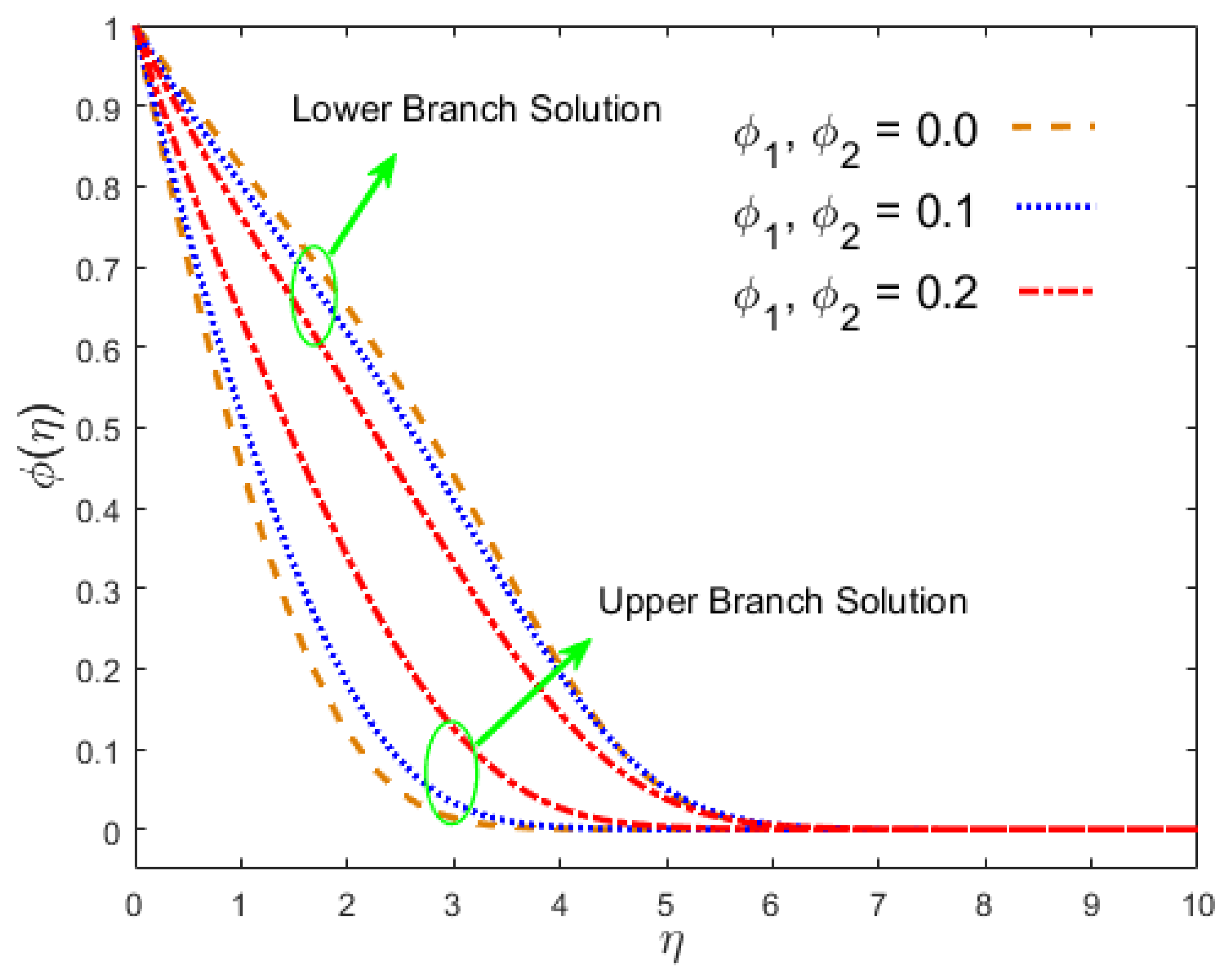
In this section, we look at the problem formulation where the model consists of highly nonlinear partial differential equations (PDE) [1,2,3,4,5], and the exact solution of such a model is quite complicated and seems impossible if the number of parameters involved in the problem is greater than the control of the solution. In our case, the problem was, firstly, tackled numerically through the bvp4c package in MATLAB, where we could exercise the similarity transformations along with the aforementioned PDEs transmuted into nonlinear ODEs [9,10,11,12] with the related constraint equation [13]. The pertinent parameters in the problem that were taken to be fixed for computational purposes throughout the process were the following [37]: D u = M = 0.2 , R d = S c = 0.5 ,   θ w = 0.5 ,   S r = 0.3 , ϕ 1 = ϕ 2 = 0.1 , S = 1.5 , and λ = 0.5 . The values of the hybrid nanoparticle volume fraction and the Prandtl number lay in the range ( 0 ϕ 1 < 1 , 0 ϕ 2 < 1 ) and ( 6.2 ) , respectively. On the other hand, Oztop and Abu-Nada [38] investigated the regular viscous fluid when ϕ 1 = ϕ 2 = 0 . The dual solutions (more than one solution) were obtained numerically to analyze the MHD impact on non-linear radiative hybrid nanoliquid flow for the hybrid alloy nanomaterials made of AA7075 and Ti6Al4V nanoparticles along with the base fluid, water. The (Sr) and (Du) numbers imposed in the concentration and energy equations were taken, respectively, also travelling along the secondary or stream-wise and cross flow directions. Physically, the stable and unstable solutions, called the upper and lower branch solutions for the corresponding parameters, respectively, were plotted in various graphs. In the entire study, the smaller solid red circles display the critical points at which both branches change their solutions. For computational purposes, the thermo-physical features of the AA 7075 and Ti 6 Al 4 V hybrid alloy nanomaterials, along with the host fluid, water, are shown in Table 2. Figure 2 is prepared to test the numerical scheme via the accessible graphical results of Bhattacharyya and Pop [33] in the case of the stream-wise direction in the restrictive case. The assessments confirm a marvelous harmony between the current and available graphical results.
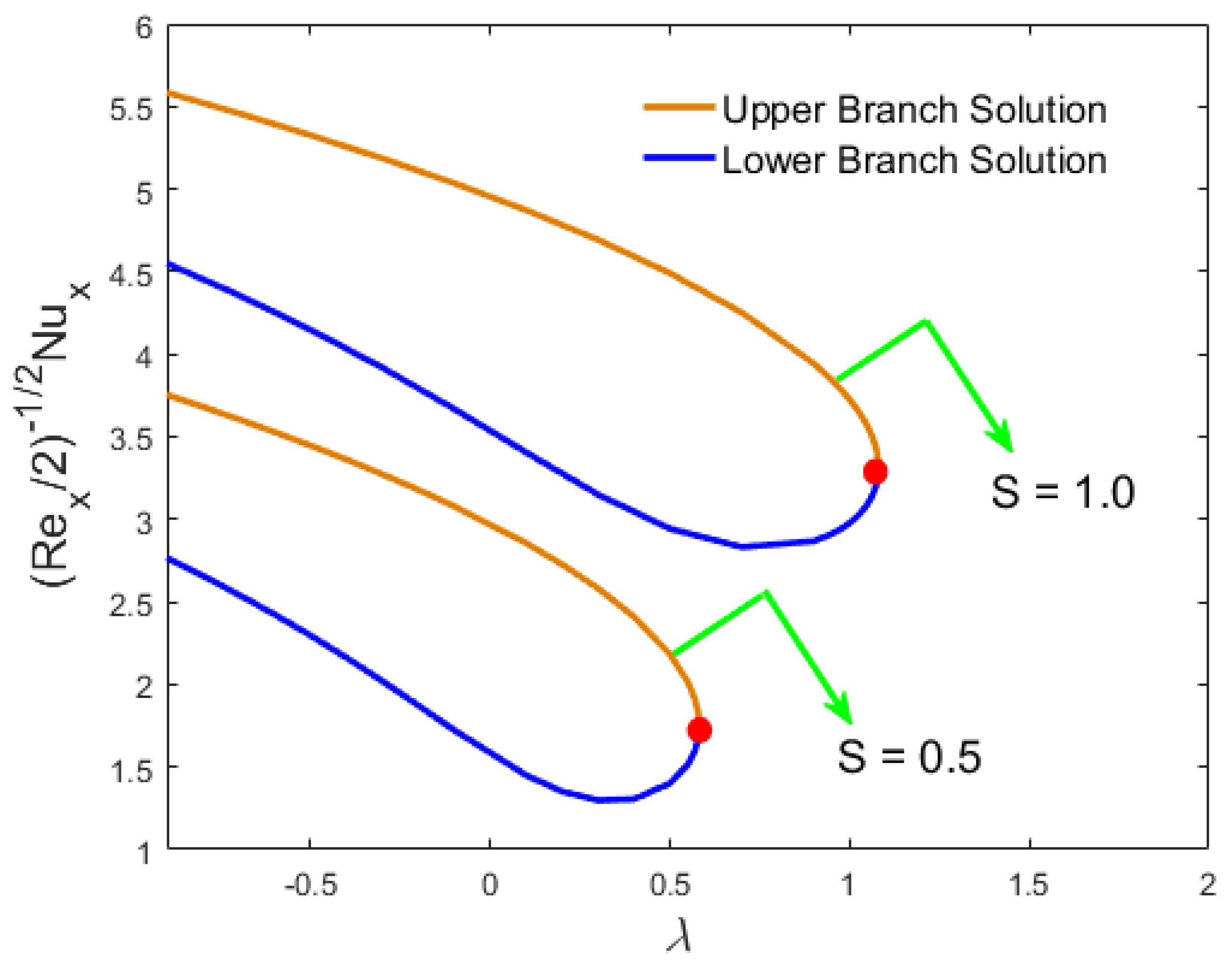
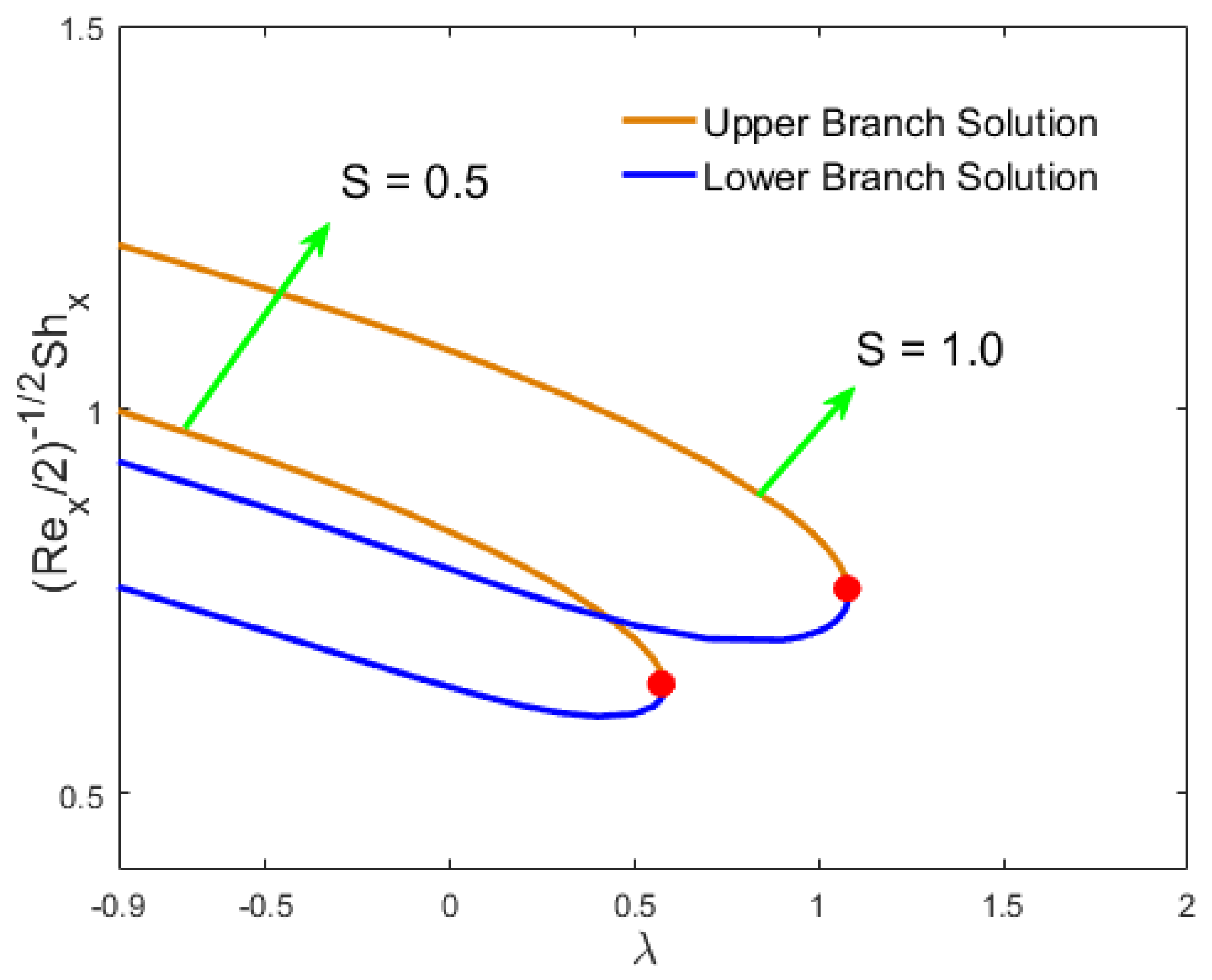
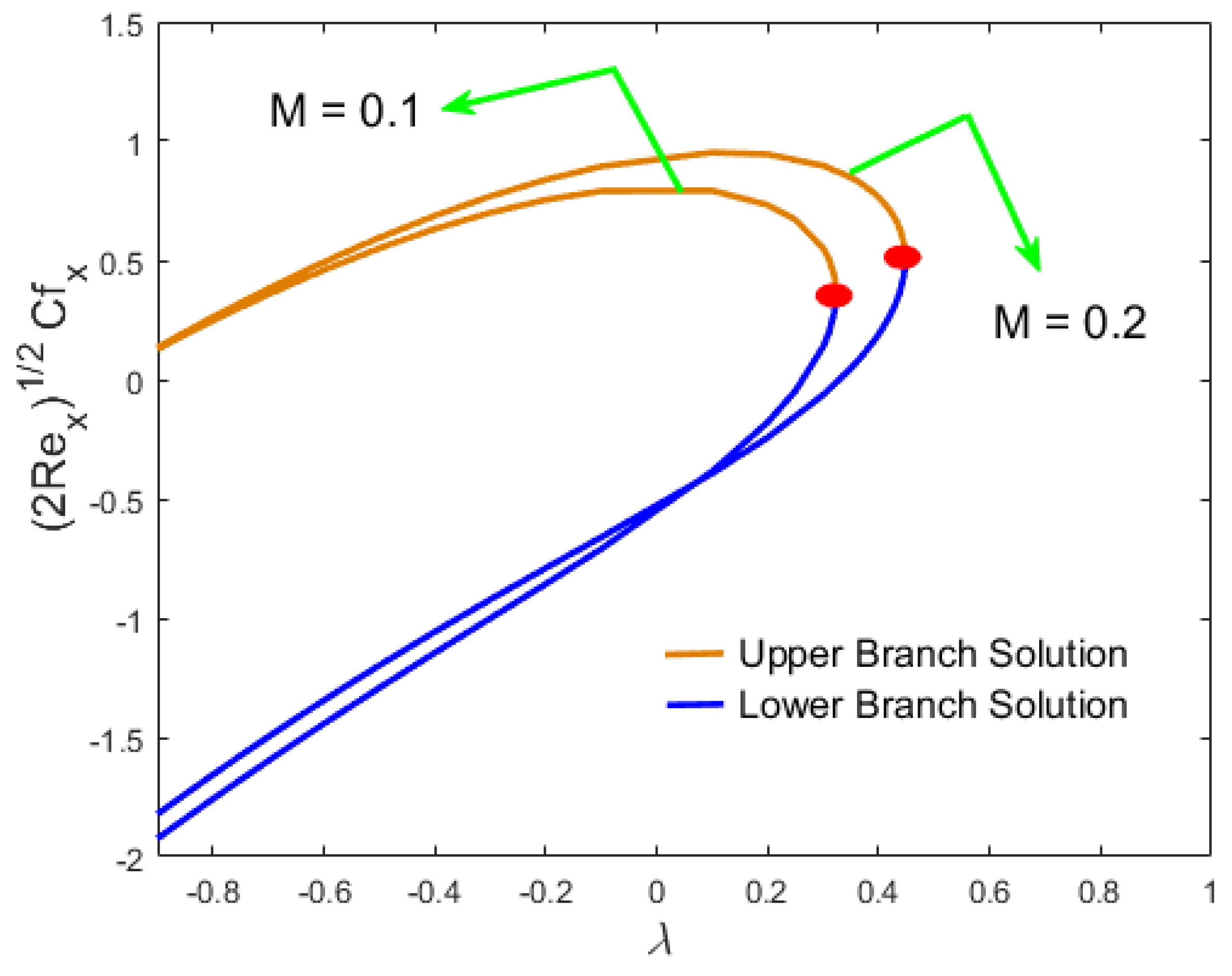
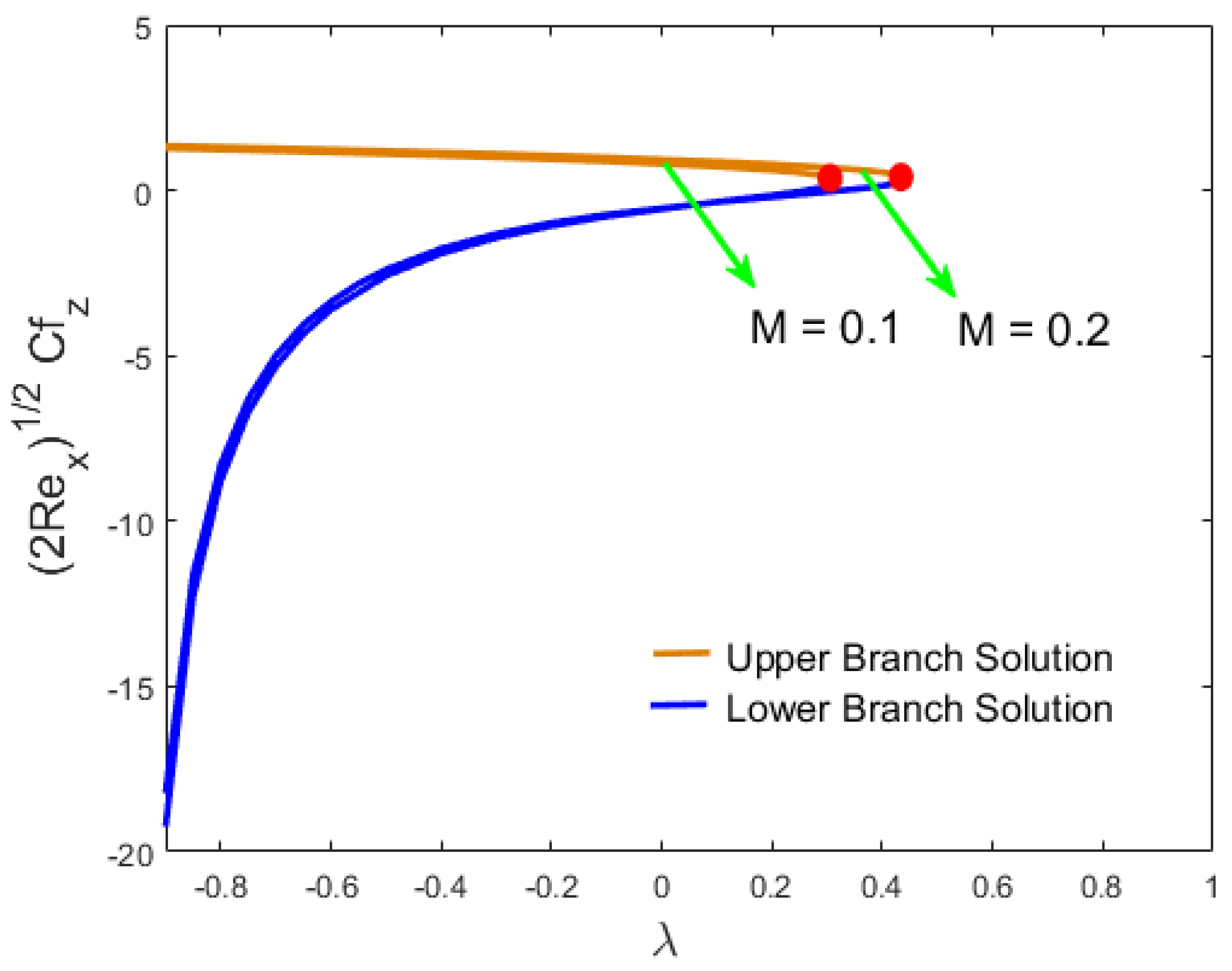
Figure 3 and Figure 4 display the impact of the S parameter against the shrinking/stretching parameter λ for the skin factor coefficients along the stream-wise direction ( 2 Re x ) 1 / 2 C f x and the cross flow direction ( 2 Re x ) 1 / 2 C f z , while the influences of the same parameter against λ on the heat transfer ( Re x / 2 ) 1 / 2 N u x and the mass transfer ( Re x / 2 ) 1 / 2 S h x rate are emphasized in Figure 5 and Figure 6, respectively. The solution behavior and the critical values of the local skin factor coefficients ( ( 2 Re x ) 1 / 2 C f x , ( 2 Re x ) 1 / 2 C f z ) , the local heat transfer ( Re x / 2 ) 1 / 2 N u x , and the mass transfer ( Re x / 2 ) 1 / 2 S h x against λ ( λ c = 0.58193 ,   1.08110 ) for the two changed values of the parameter { S = 0.5 ,   1.0 } are exposed in Figure 3, Figure 4, Figure 5 and Figure 6, respectively. It can be discerned from Figure 3 that the lower branch solution failed to increase, while the upper solution was boosted with increasing S . It was further noted that the solution for the ( 2 Re x ) 1 / 2 C f x was coarser in the shrinking case ( λ < 0 ) than that detected for the case of stretching ( λ > 0 ) . Figure 4 illustrates the same behavior as in Figure 3 for the skin coefficient along the cross flow direction ( 2 Re x ) 1 / 2 C f z against the moving parameter λ as the choice for the numerals of the suction parameter decreases; the upper solution showed a downtrend in motion while the lower solution showed an uptrend. Generally, the skin friction augmented as we increased the parameter S against the moving parameter λ due to the inverse relation with the velocity, and by way of a consequence, the momentum boundary layer was thicker and blooming in the first solution and thinner in the second solution, as depicted in Figure 3 and Figure 4. The influences of the mass suction parameter S for the two different values against the non-dimensional constant λ (say, moving parameter) for the Nusselt and Sherwood numbers were calculated and presented graphically in Figure 5 and Figure 6, respectively. It is observed individually for both branches in Figure 5 that when the values of S decreases against λ for the heat transfer profile, both branches of the solutions changed. Moreover, this solution behavior totally changes in Figure 6 for the rate of mass transfer, which decreases as the value of S decays. In the situation in terms of the plate moving into the origin for λ > 0 , both the local Nusselt number and local Sherwood number became smaller as compared to the case out of the origin λ < 0 , but in comparison with Figure 3 and Figure 4, this situation is totally different, such as the mass and heat transfer rate computed in terms of ( Re x / 2 ) 1 / 2 S h x and ( Re x / 2 ) 1 / 2 N u x were lower for λ > 0 than examined for λ < 0 . The variation of the magnetic constraint M for the two different values against the shrinking/stretching parameter λ for the skin factor along the stream-wise and the cross flow directions, the rate of heat, and mass transfer are mathematically calculated in terms of the expressions like ( 2 Re x ) 1 / 2 C f x , ( 2 Re x ) 1 / 2 C f z , ( Re x / 2 ) 1 / 2 N u x , and ( Re x / 2 ) 1 / 2 S h x , which are behaviorally emphasized in Figure 7, Figure 8, Figure 9 and Figure 10, respectively.
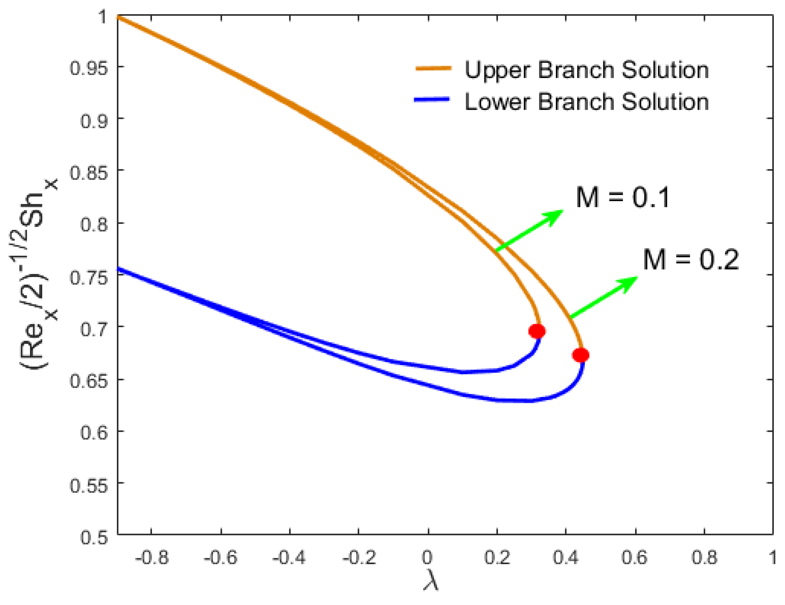
The skin factor along the (STW) and (CRF) directions, which was computed by the expression ( 2 Re x ) 1 / 2 C f x and ( 2 Re x ) 1 / 2 C f z , is portrayed in Figure 7 and Figure 8, respectively, where the parameter M is imposed against λ , whose critical values are ( λ c = 0.32530 ,   0.44890 ) . Figure 7 clarifies that as the value of the magnetic parameter decreases, the values of ( 2 Re x ) 1 / 2 C f x went down in both branch solutions in the range of ( λ < 0 ) , and then went up for the second branch solution in the range ( λ > 0 ) . In addition, it was predicted clearly in the figure that the values of ( 2 Re x ) 1 / 2 C f x for the situation of shrinking were lower than the circumstance of stretching. Figure 8 displays the behavior of the solution as different from Figure 7; here, the values of ( 2 Re x ) 1 / 2 C f z changed with the decrease of magnetic parameter M . Figure 9 and Figure 10 elucidate the influence of M on the rate of heat and mass transfer along the dimensionless constant λ , respectively. The critical points along the moving parameter λ for the two selected values of M were considered as ( λ c = 0.32530 ,   0.44890 ) for both the mass and heat transfer rate, respectively. Clearly, from the graphical results, the reverse trend of these multiple solutions can be observed in both of these figures. In a more compact way, it was interpreted that for the finer choices of M , the first branch solution showed a declining behavior, whilst for the second branch solution, an uptrend behavior was perceived. In addition, such graphs exemplified that the erratic engineering features like mass and heat transfer rate were quite fine for the lower branch as compared to the upper branch solution.
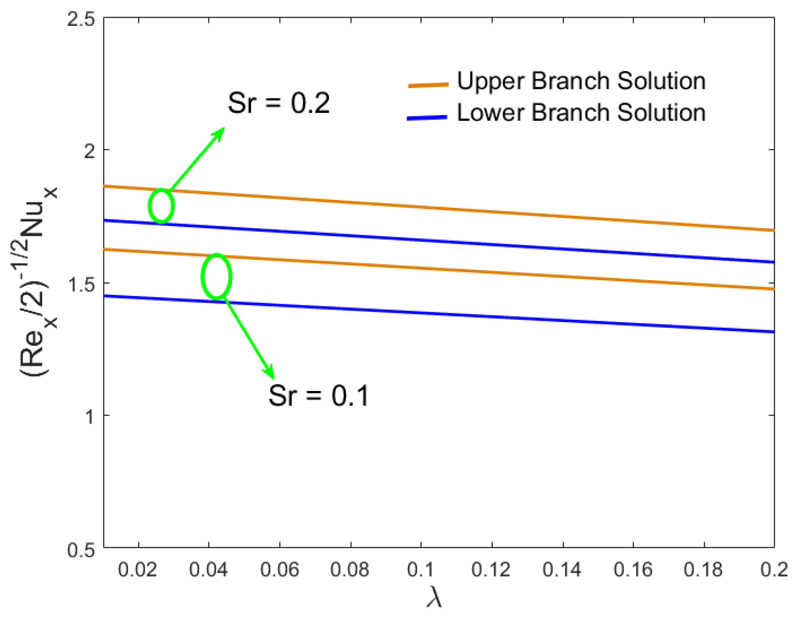
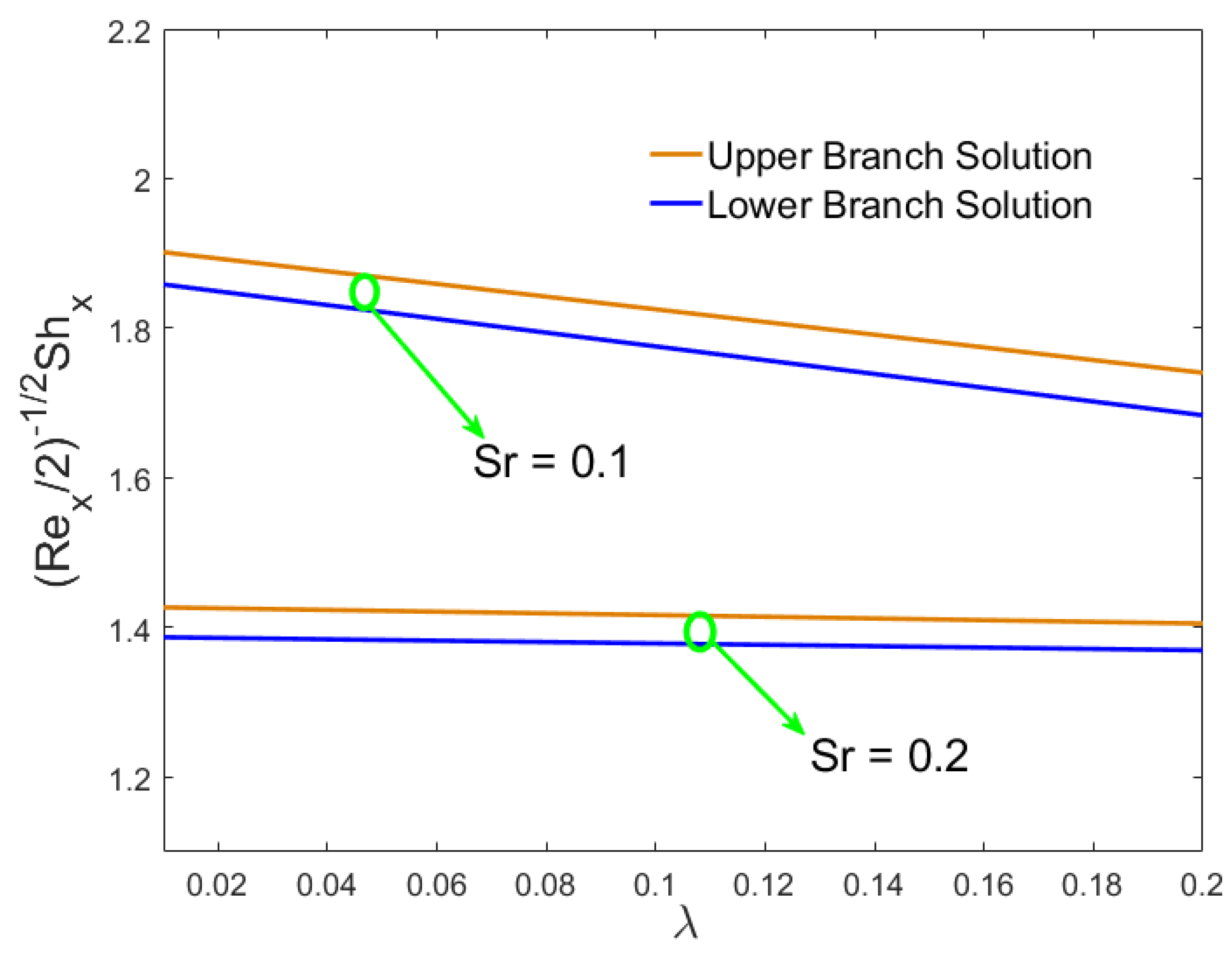
Figure 11, Figure 12, Figure 13 and Figure 14 illustrate the effect of the Dufour and Soret numbers on the heat and mass transfer rate against the moving parameter λ , respectively. Furthermore, Figure 11 displays the Dufour effect of the two different values on ( Re x / 2 ) 1 / 2 N u x against λ . The value of the Dufour parameter increases, and as a result, both branches of the solutions showed a decaying behavior, while the reverse behavior was detected for ( Re x / 2 ) 1 / 2 S h x as the Dufour parameter uplifts, highlighted in Figure 12. The influences of the Soret ( S r = 0.1 , 0.2 ) parameter against λ for the Nusselt and Sherwood numbers are investigated in Figure 13 and Figure 14, respectively. The local heat transfer was growing in both branch solutions along parameter λ as the Soret number upsurges, while the contradictory behavior was noticed for the mass transfer rate.
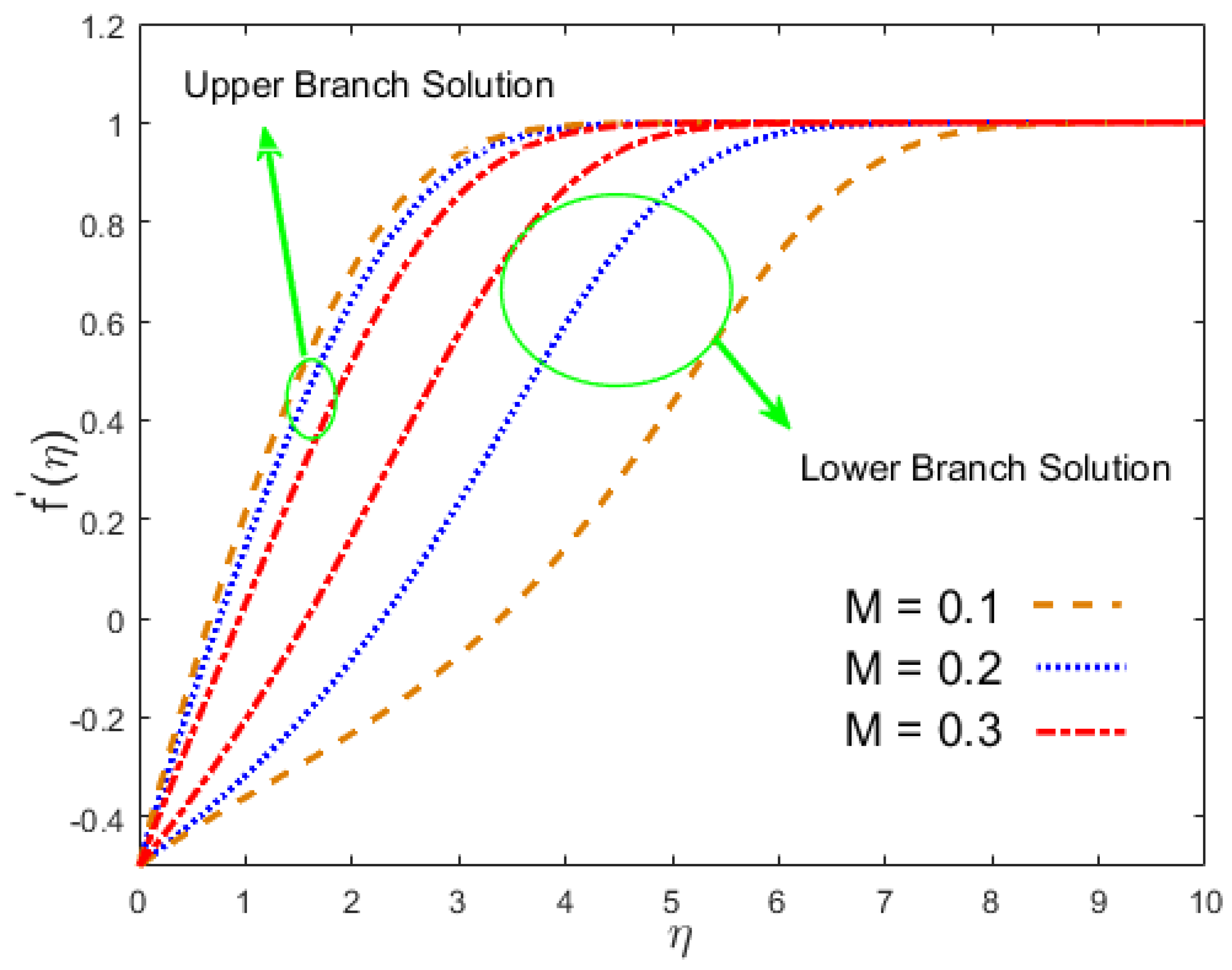
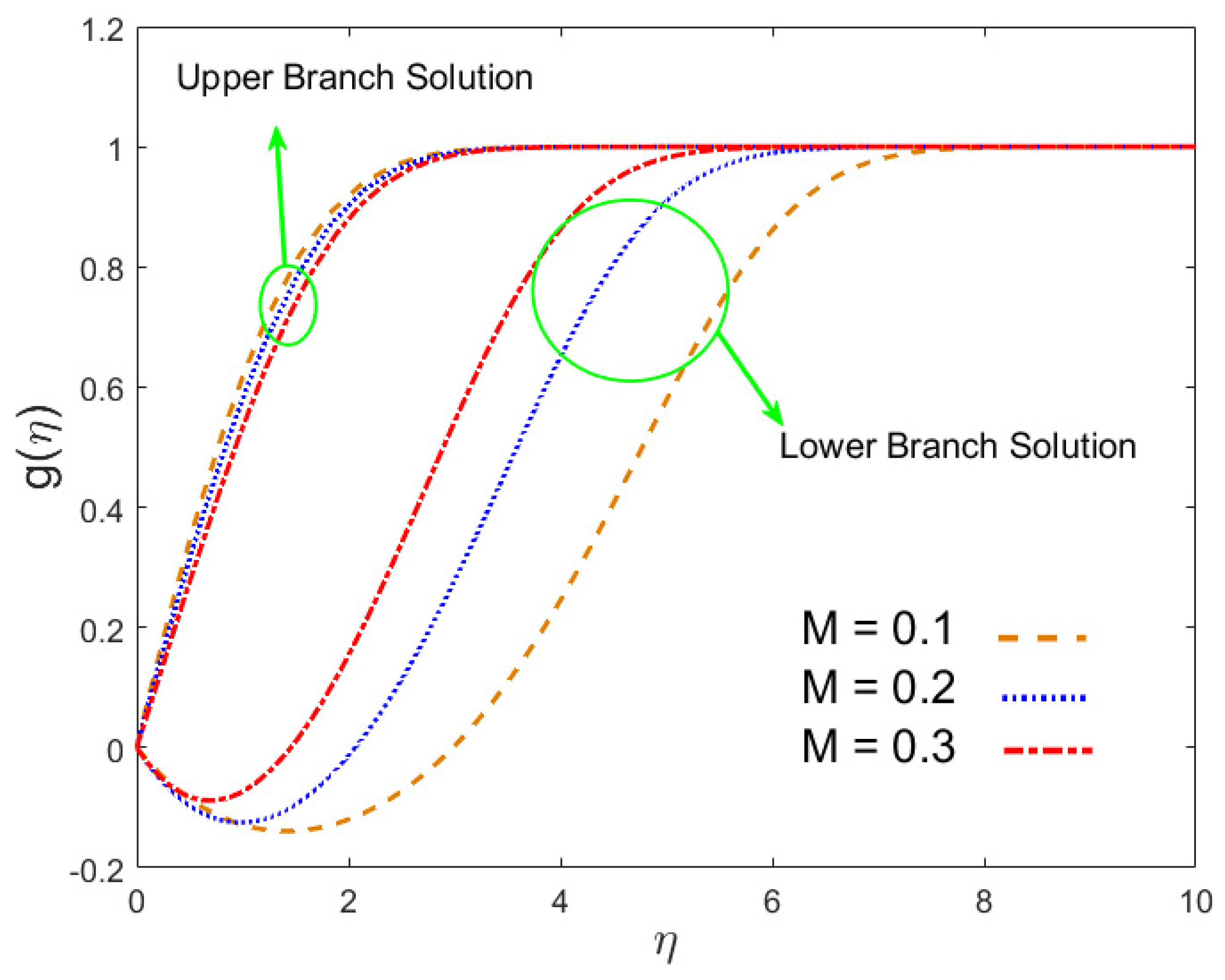
The influence of the magnetic field parameter for the three different selected values in terms of computing the velocities in the stream-wise direction f ( η ) and the cross flow direction g ( η ) is highlighted graphically in Figure 15 and Figure 16. This showed that the first solution, which is also called the lower branch solution, decreased in both aforementioned graphs and the second solution, called the upper branch, was growing as the values of M changed. Physically, one could notice this obvious behavior due to the change of the magnetic parameter creating a large Lorentz (drag) force, which retarded the motion of the fluids significantly, and thus, the profiles in terms of the velocity and the boundary layer thickness decelerated as the magnetic parameter increased.
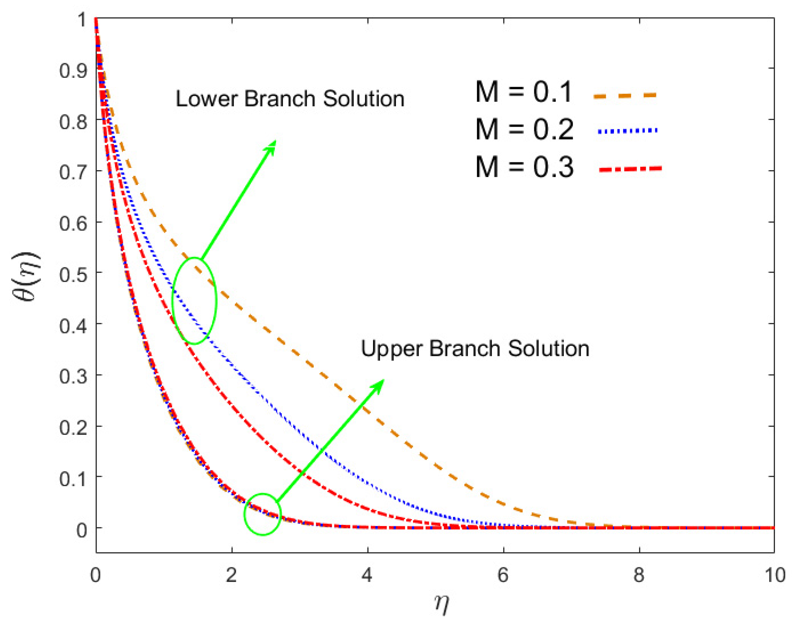
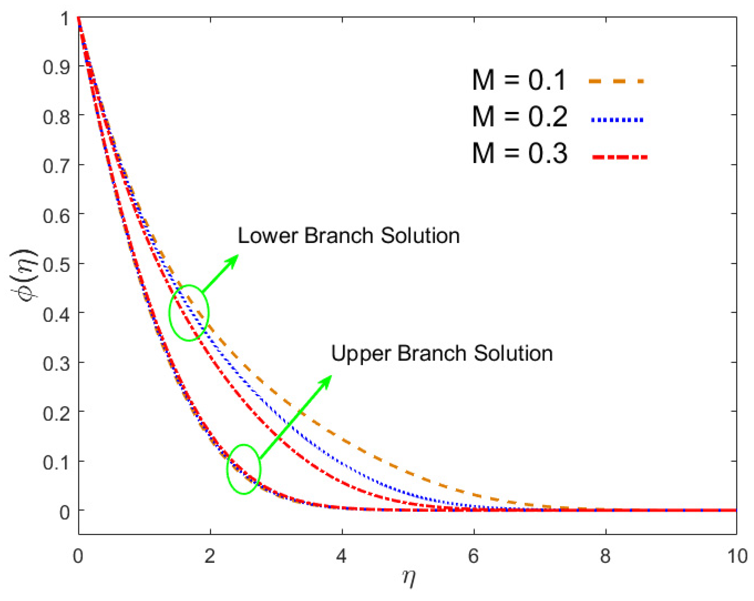
Figure 17 and Figure 18 display the flow trend of the fields such as temperature θ ( η ) and concentration ϕ ( η ) for the numerous values of M , respectively. It is discerned from Figure 17 that by increasing M , the behavior of the solution for the temperature increased in the upper branch. Physically, the strong Lorentz force dropped to slow down the fluid flow, which, accordingly, caused extra friction amid the fluid molecules. Thus, additional heat was generated, therefore increasing the temperature of fluid. However, this trend totally changed in the behavior of the second branch solution; the temperature profile declined with growing M . A similar behavior is noticed in Figure 18 as in Figure 17, which shows that the influence of the magnetic field constraint on the concentration profile of the hybrid nanofluid was increased in the first branch solution, while it decreased in the second branch solution.
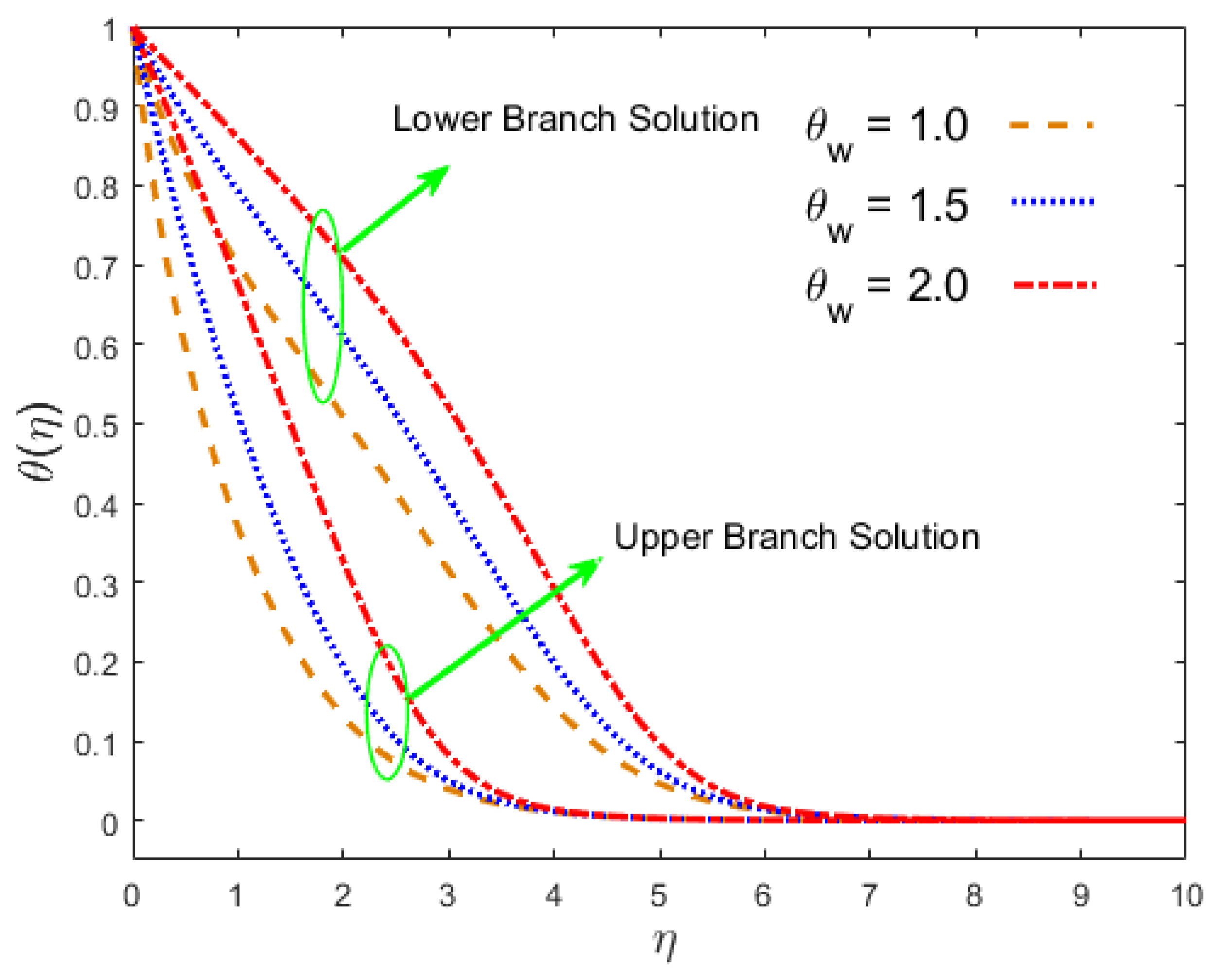
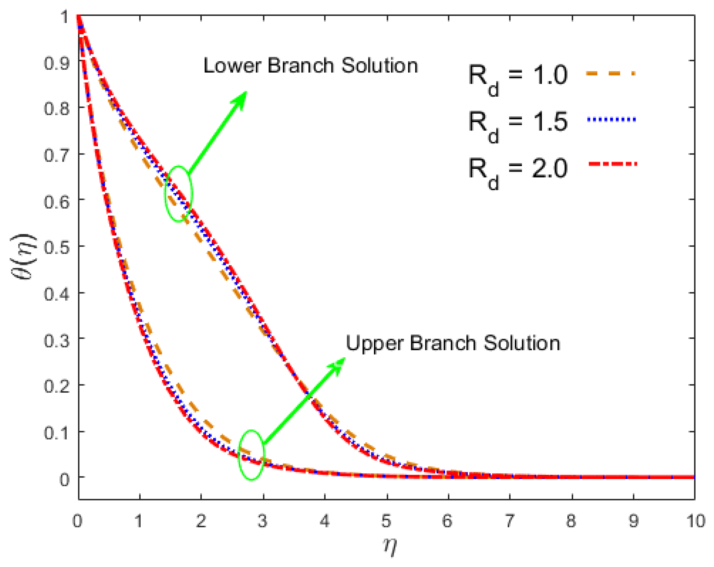
Figure 19 shows the influence of the temperature ratio parameter θ w on the temperature profile. It is observed clearly from its graphical results that both branch solutions became higher for the three different ascending values of θ w . Figure 20 shows that the first solution decreased for the temperature profile θ ( η ) , and the second solution increased as the radiation parameter R d became successively larger. A greater amount of radiation implied the dominance of conduction, and thus, the thermal boundary layer thickness diminished. The effect of the Schmidt parameter S c on ϕ ( η ) is depicted in Figure 21. Moreover, its shows that the behavior of the multiple or dual solution and the concentration of the boundary layer decelerated in both the branches of outcomes due to changing the values of S c . The Schmidt number exemplified the ratio of kinematic viscosity to molecular mass diffusivity for the enhancement of Sc, which differed from a decline in mass diffusivity in the system, and which consequently lowered the concentration profile.
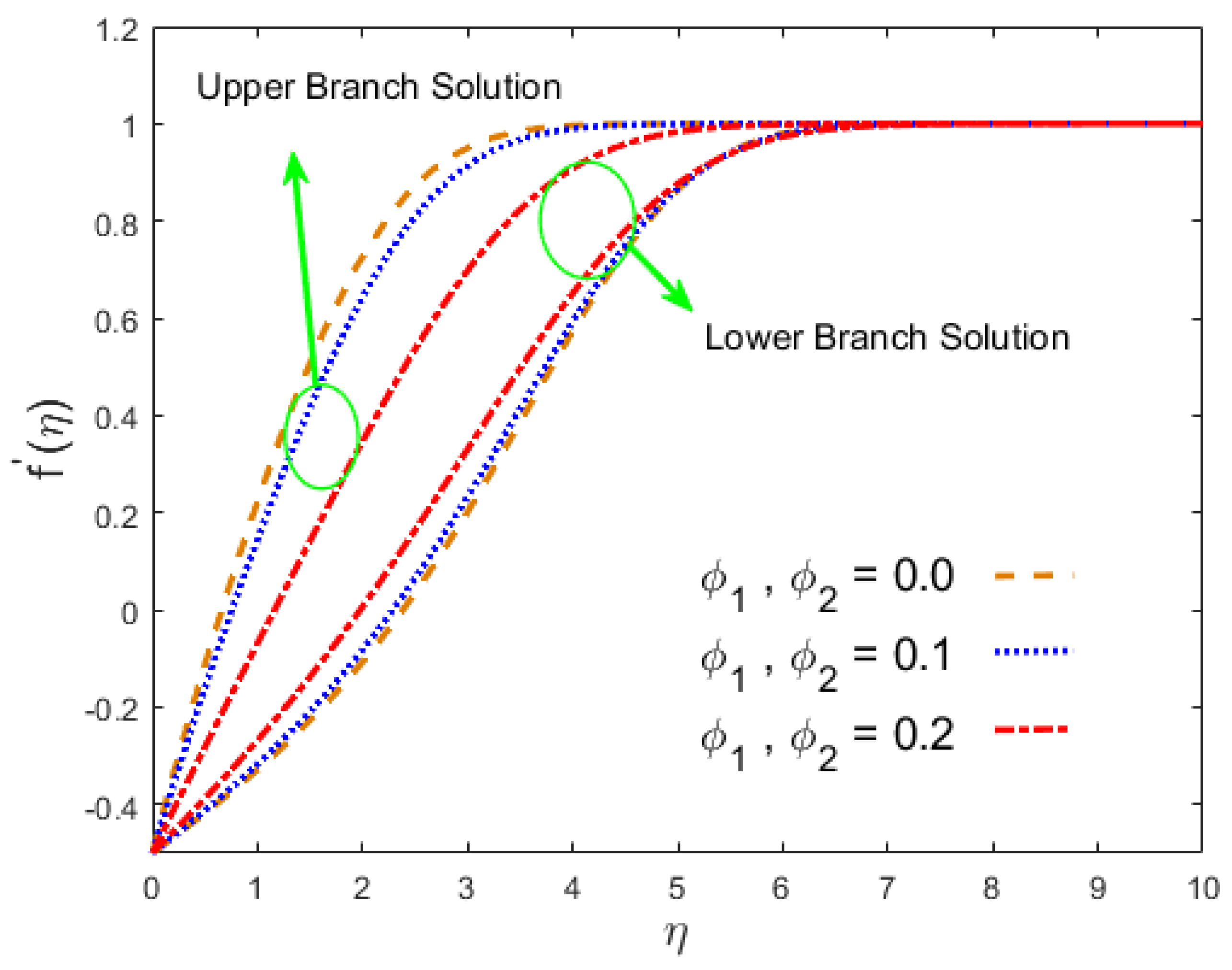
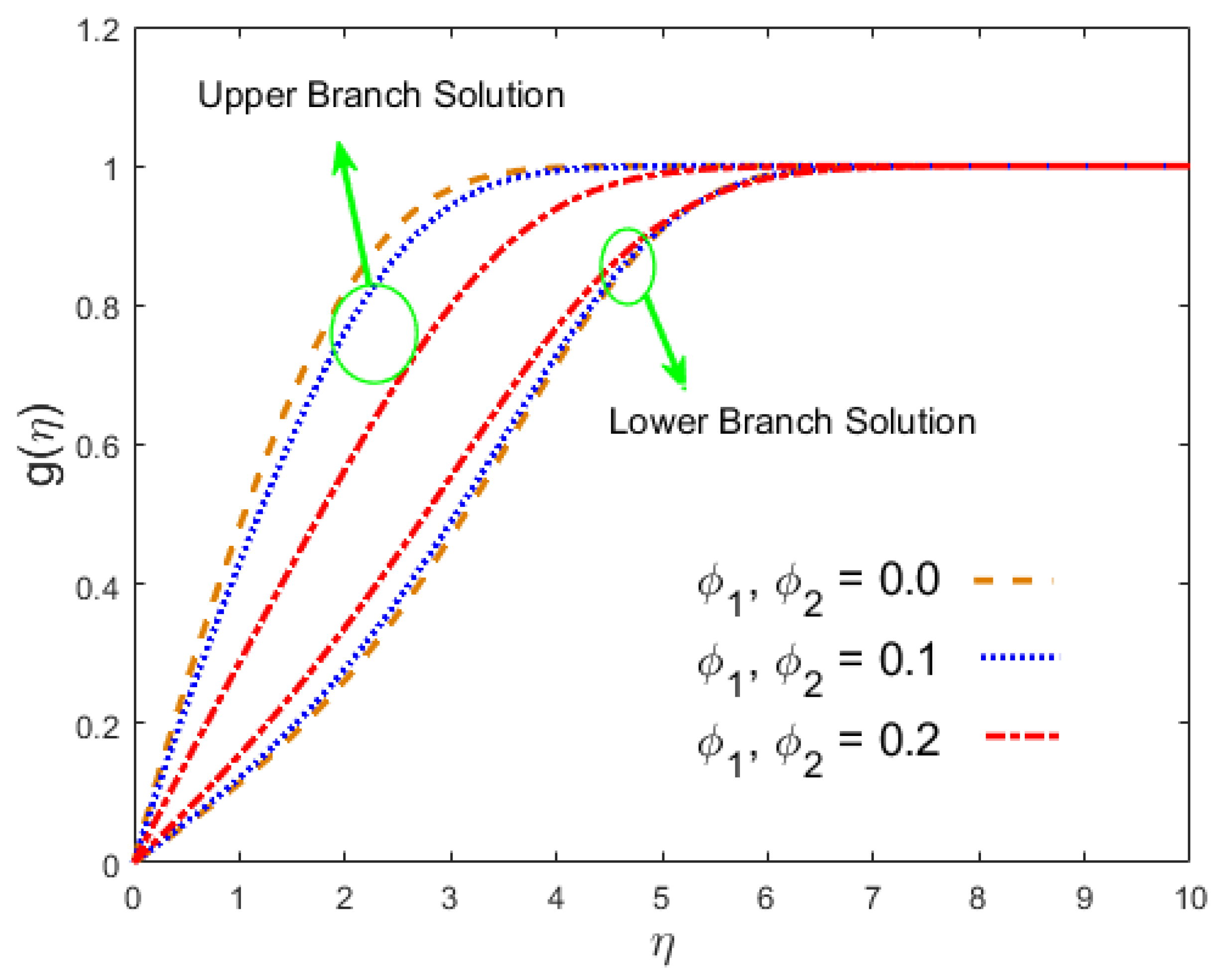
Figure 22, Figure 23, Figure 24 and Figure 25 show the impacts of the hybrid nanomaterial parameters ϕ 1 ,   ϕ 2 on the velocity in the stream-wise direction f ( η ) , the velocity in the cross flow direction g ( η ) , temperature distribution θ ( η ) , and the concentration profile ϕ ( η ) , respectively. Further, it was observed that when the values of the hybrid alloy nanomaterials ϕ 1 ,   ϕ 2 increase, the first solution decreases, while the lower solution increases in the velocities profile, and their graphical behavior is captured in Figure 22 and Figure 23, respectively. This is apparent from the reality that greater amounts of ϕ 1 ,   ϕ 2 communicate to intensify the hybrid nanofluids thermal conductivity, which inspires the diffusion of heat so that the heat impulsively disperses near the surface. Figure 24 and Figure 25 present the importance of the hybrid alloy nanomaterials ϕ 1 ,   ϕ 2 on the temperature and concentration profiles. More precisely, it is noted that the temperature and the nanofluid concentration is enhanced in both branches of the solution (lower and upper) when ϕ 1 ,   ϕ 2 upsurge. Since, the large amounts of ϕ 1 ,   ϕ 2 generate a great quantity of energy during the flow connected with the uneven progress of the ultrafine materials, they, hence, produce a substantial improvement in the rate of heat and mass transfer, which consequently augments the temperature and the concentration.

4. Conclusions

This research explored the effects of the Dufour and Soret numbers on magneto flow comprised of two hybrid alloy nanoparticles, namely AA7075 and Ti6Al4V, in the secondary and stream-wise flow directions. Furthermore, the nonlinear radiation effect was studied. Numerical dual solutions are achieved through the bvp4c solver. The significant points are gathered as follows:
  • For the first solution, the velocity of the nanoliquid increased in the stream-wise and cross flow directions with a suction parameter, while a change in pattern was observed in the second solution. For both solutions, the concentration and temperature of the nanoparticles decreased.
  • In the first solution, the magnetic field constraint reduced the velocity of the nanofluid, and it increased in the lower branch result, whereas in the upper branch result, the temperature and concentration rose and decreased in the lower branch solution.
  • The temperature distribution changed due to θ w in both results, whereas the impact of radiation was the opposite manner.
  • The nanoliquid velocity decreased in the first result due to the hybrid nanoparticles, while the opposite pattern was seen in the second test. In both cases, the concentration and temperature fields increased.
  • The Nusselt number increased in the first and second solutions because of the Soret numbers, while the reverse behavior was seen because of the Dufour numbers.
  • In both results, the effect of the magnetic number induced an increase in skin friction in the stream-wise and cross flow directions. However, in the first solution, the Nusselt number and the Sherwood number declined and increased in the second solution.

Author Contributions

Conceptualization, U.K. and A.Z.; methodology, U.K.; software, A.Z.; validation, I.K., A.Z. and U.K.; formal analysis, U.K.; investigation, D.B.; resources, data curation, U.K. and A.Z.; writing, original draft preparation, I.K. and writing, review and editing, I.K. visualization, K.S.N.; supervision, A.Z.; project administration, K.S.N.; funding acquisition, D.B.; software, editing, and validation, U.K. All authors read and agreed to the published version of the manuscript.

Funding

This research was funded by Deanship of Scientific Research at Prince Sattam Bin Abdulaziz University under the research project No. 2020/01/16436.

Acknowledgments

This project was supported by the Deanship of Scientific Research at Prince Sattam Bin Abdulaziz University under the research project No. 2020/01/16436.

Conflicts of Interest

The authors declare no conflict of interest.

Nomenclature

α ^ f thermal diffusivity
B 0 intensity of the magnetic field
C Concentration
C ambient fluid concentration
C w wall concentration
C f x , C f z skin friction coefficients
c ^ p specific heat
D ^ f mass diffusivity
D u Dufour number
f , g dimensionless velocities
k * coefficient of mean absorption
k ^ thermal conductivity
M magnetic parameter
N u x Nusselt number
Pr Prandtl number
q r radiative heat flux
R d radiation parameter
Re x local Reynolds number
SSuction
ScSchmidt number
S r Soret number
S h x Sherwood number
T Temperature
T free-stream temperature
T w wall temperature
U 0 constant velocity
w 0 transverse velocity
( u , v , w ) velocity components
( x , y , z ) Cartesian coordinates

Greek Symbols

λ moving parameter
μ ^ dynamic viscosity
ϕ 1 , ϕ 2 volume fractions of nanoparticles
θ dimensionless temperature
θ w ( = T f / T ) temperature ratio parameter
χ dimensionless concentration
ν f kinematic viscosity of base fluid
ρ ^ Density
σ * Stefan–Boltzmann constant
σ ^ electrical conductivity
ψ stream function
η similarity variable

Subscripts

s 1 , s 2 solid nanoparticles
hbnfhybrid nanofluid
Fbase fluid

Superscripts

derivative w.r.t. η

Appendix A

To calculate the Equation (9), we need to first find the components ( u , v ) by using the definition of the stream function u = ψ y , v = ψ x . Thus, we get
u = U 0 f ( η )   and   v = ( U 0 v f 2 x ) 1 2 ( η f ( η ) f ( η ) ) ,
u u x = U 0 2 η 2 x f f ,
v u y = ( U 0 2 2 x ) ( η f f f f ) .
Now, adding Equations (A2) and (A3), we get
u u x + v u y = U 0 2 2 x f f ,
2 u y 2 = U 0 2 2 ν f x f ,
B 2 ( x ) = B 0 2 2 x .
Now, putting the above expressions in Equation (2), we get the desired form
U 0 2 2 x f f = μ ^ h b n f ρ ^ h b n f ( U 0 2 2 ν f x f ) + σ ^ h b n f ρ ^ h b n f B 0 2 2 x ( U 0 U 0 f ) ,
Now, multiply the equation both sides by 2 x U 0 2 . Thus,
μ ^ h b n f ρ ^ h b n f ν f f + f f + σ ^ h b n f ρ ^ h b n f B 0 2 U 0 ( 1 f ) = 0 ,
Further simplifying Equation (A7), we get
μ ^ h b n f μ ^ f f + ρ ^ h b n f ρ ^ f f f + M σ ^ h b n f σ ^ f ( 1 f ) = 0 ,
Using the thermo physical properties in Table 1, it becomes
f + β 1 { β 2 f f M β 3 ( f 1 ) } = 0 ,
in which
β 1 = ( 1 ϕ 1 ) 2.5 ( 1 ϕ 2 ) 2.5 ,
β 2 = ( ( 1 ϕ 2 ) { ( 1 ϕ 1 ) + ϕ 1 ρ ^ s 1 ρ ^ f } + ϕ 2 ρ ^ s 2 ρ ^ f ) ,
β 3 = ( σ ^ s 2 ( 1 + 2 ϕ 2 ) + 2 σ ^ b f ( 1 ϕ 2 ) σ ^ s 2 ( 1 ϕ 2 ) + σ ^ b f ( 2 + ϕ 2 ) ) ( σ ^ s 1 ( 1 + 2 ϕ 1 ) + 2 σ ^ f ( 1 ϕ 1 ) σ ^ s 1 ( 1 ϕ 1 ) + σ ^ f ( 2 + ϕ 1 ) ) , M = σ f B 0 2 ρ f U 0 .
Now, to calculate the Equation (10), we need
w x = η 2 x w 0 g ,
w y = w 0 ( U 0 2 ν f x ) 1 2 g ,
u w x = η 2 x U 0 w 0 g f ,
v w y = w 0 U 0 2 x ( η g f g f ) ,
2 w y 2 = w 0 U 0 2 ν f x g .
Putting Equations (A6), (A11)–(A13) in Equation (3), we get
w 0 U 0 2 x ( η g f g f ) η 2 x U 0 w 0 g f = μ ^ h b n f ρ ^ h b n f ( w 0 U 0 2 ν f x g ) + σ ^ h b n f ρ ^ h b n f B 0 2 2 x ( w 0 w 0 g ) ,
Now, further simplifying the above equation, we get
μ ^ h b n f μ ^ f g + σ ^ h b n f σ ^ f M ( 1 g ) + ρ ^ h b n f ρ ^ f g f = 0 ,
Using the thermo physical properties in Table 1, it becomes
g + β 1 { β 2 f g β 3 M ( g 1 ) } = 0 ,
in which
β 1 = ( 1 ϕ 1 ) 2.5 ( 1 ϕ 2 ) 2.5 ,
β 2 = ( ( 1 ϕ 2 ) { ( 1 ϕ 1 ) + ϕ 1 ρ ^ s 1 ρ ^ f } + ϕ 2 ρ ^ s 2 ρ ^ f ) ,
β 3 = ( σ ^ s 2 ( 1 + 2 ϕ 2 ) + 2 σ ^ b f ( 1 ϕ 2 ) σ ^ s 2 ( 1 ϕ 2 ) + σ ^ b f ( 2 + ϕ 2 ) ) ( σ ^ s 1 ( 1 + 2 ϕ 1 ) + 2 σ ^ f ( 1 ϕ 1 ) σ ^ s 1 ( 1 ϕ 1 ) + σ ^ f ( 2 + ϕ 1 ) ) , M = σ f B 0 2 ρ f U 0 .
Now, to calculate the Equation (11), we need
T x = η 2 x ( T w T ) θ ,
u T x = η U 0 2 x ( T w T ) f θ ,
T y = ( U 0 2 x ν f ) 1 2 ( T w T ) θ ,
v T y = U 0 2 x ( T w T ) ( η f θ f θ ) ,
2 T y 2 = U 0 2 x ν f ( T w T ) θ ,
2 C y 2 = U 0 2 x ν f ( C w C ) ϕ ,
T 2 = ( θ ( θ w 1 ) + 1 ) 2 T 2   where   θ w = T w T   ,
q r y = 16 σ * 3 k * { 3 T 2 ( T y ) 2 + T 3 2 T y 2 } .
Putting Equations (A17), (A19) and (A21) in Equation (A21), we get
q r y = 16 σ * 3 k * { 3 ( θ ( θ w 1 ) + 1 ) 2 T 2 U 0 2 x ν f ( T w T ) 2 θ 2 + ( θ ( θ w 1 ) + 1 ) 3 T 3 U 0 2 x ν f ( T w T ) θ } ,
Further simplified, we get
q r y = 16 σ * T 3 3 k * { 3 ( θ ( θ w 1 ) + 1 ) 2 U 0 2 x ν f ( θ w 1 ) ( T w T ) θ 2 + ( θ ( θ w 1 ) + 1 ) 3 U 0 2 x ν f ( T w T ) θ } ,
Putting the above expressions in Equation (4), it becomes
U 0 2 x ( T w T ) ( η f θ f θ ) η U 0 2 x ( T w T ) f θ = α ^ h b n f U 0 2 x ν f ( T w T ) θ + D m k T c s c ^ p U 0 2 x ν f ( C w C ) ϕ + 1 ( ρ ^ c ^ p ) h b n f 16 σ * T 3 3 k * { 3 ( θ ( θ w 1 ) + 1 ) 2 U 0 2 x ν f ( θ w 1 ) ( T w T ) θ 2 + ( θ ( θ w 1 ) + 1 ) 3 U 0 2 x ν f ( T w T ) θ } ,
Now, simplifying the expression, it becomes
( ρ ^ c ^ p ) h b n f ( ρ ^ c ^ p ) f f θ = k ^ h b n f k ^ f Pr θ + ( ρ ^ c ^ p ) h b n f ( ρ ^ c ^ p ) f D u ϕ + 4 3 Pr R d { 3 ( θ ( θ w 1 ) + 1 ) 2 ( θ w 1 ) θ 2 + ( θ ( θ w 1 ) + 1 ) 3 θ } ,
( k ^ h b n f k ^ f + 4 3 R d ( θ ( θ w 1 ) + 1 ) 3 ) θ + Pr ( ρ ^ c ^ p ) h b n f ( ρ ^ c ^ p ) f ( D u ϕ + f θ ) + 4 R d ( θ ( θ w 1 ) + 1 ) 2 ( θ w 1 ) θ 2 ,
( ( θ ( θ w 1 ) + 1 ) 3 + 3 4 R d k ^ h b n f k ^ f ) θ + 3 4 R d Pr ( ρ ^ c ^ p ) h b n f ( ρ ^ c ^ p ) f ( D u ϕ + f θ ) + 3 ( θ ( θ w 1 ) + 1 ) 2 ( θ w 1 ) θ 2 ,
Using the thermo physical properties in Table 1, it becomes
θ [ ( θ ( θ w 1 ) + 1 ) 3 + 3 4 R d β 4 ] + 3 4 β 5 R d Pr ( f θ + D u ϕ ) + 3 ( θ w 1 ) ( θ ( θ w 1 ) + 1 ) 2 ( θ ) 2 = 0 ,
in which:
β 4 = { k ^ s 2 + 2 k ^ nf 2 ϕ 2 ( k ^ n f k ^ s 2 ) k ^ s 2 + 2 k ^ nf + ϕ 2 ( k ^ n f k ^ s 2 ) } { k ^ s 1 + 2 k ^ f 2 ϕ 1 ( k ^ f k ^ s 1 ) k ^ s 1 + 2 k ^ f + ϕ 1 ( k ^ f k ^ s 1 ) } ,
β 5 = ( ( 1 ϕ 2 ) [ ϕ 1 ( ρ ^ c ^ p ) s 1 ( ρ ^ c ^ p ) f ] + ( 1 ϕ 1 ) + ϕ 2 ( ρ ^ c ^ p ) s 2 ( ρ ^ c ^ p ) f ) , Pr = ν f α ^ f , R d = k * k ^ f 4 σ * T 3 , θ w = T w T , D u = D m k T ( C w C ) ν f c s c ^ p ( T w T ) .
Finally, to calculate Equation (12), we get
C x = η 2 x ( C w C ) ϕ ,
u C x = η U 0 2 x ( C w C ) f ϕ ,
C y = ( U 0 2 x ν f ) 1 2 ( C w C ) ϕ ,
v C y = U 0 2 x ( C w C ) ( η f ϕ f ϕ ) ,
2 T y 2 = U 0 2 x ν f ( T w T ) θ ,
2 C y 2 = U 0 2 x ν f ( C w C ) ϕ .
Now, putting Equations (A26), (A28)–(A30) in Equation (5), we get the simplified bounded form
U 0 2 x ( C w C ) f ϕ = ( D m k T T m ) U 0 2 x ν f ( T w T ) θ + D ^ h b n f U 0 2 x ν f ( C w C ) ϕ ,
Multiplying Equation (A31) both sides by 2 x U 0 ( C w C ) , we get the required form
f ϕ = S r θ + D ^ h b n f S c D ^ f ϕ ,
D ^ h b n f D ^ f ϕ + S c ( f ϕ + S r θ ) = 0 ,
Now, using the thermos-physical properties of Table 1, we get
ϕ + β 6 { S c ( f ϕ + S r θ ) } = 0 ,
in which
β 6 = ( 1 ϕ 1 ) ( 1 ϕ 2 ) , S c = ν f D ^ f , S r = D m k T ( T w T ) ν f T m ( C w C ) .
Now, to calculate the boundary equations
λ U 0 = U 0 f ( 0 ) f ( 0 ) = λ .
v = ( U 0 ν f 2 x ) 1 2 ( f η f ) v 0 ν f 2 x = ( U 0 ν f 2 x ) 1 2 f ( 0 ) f ( 0 ) = v 0 U 0 = S .
w = w 0 g 0 = w 0 g ( 0 ) g ( 0 ) = 0 .
T = θ ( T w T ) + T T w = θ ( 0 ) ( T w T ) + T θ ( 0 ) = 1 .
C = ϕ ( C w C ) + C C w = ϕ ( 0 ) ( C w C ) + C ϕ ( 0 ) = 1 .
u = U 0 f ( η ) U 0 = U 0 f ( ) f ( ) 1
w = w 0 g ( η ) w 0 = w 0 g ( ) g ( ) 1
T = θ ( T w T ) + T T = θ ( ) ( T w T ) + T θ ( ) 0 .
C = ϕ ( C w C ) + C C = ϕ ( ) ( C w C ) + C ϕ ( ) 0 .
Thus, the required boundary conditions are
f ( 0 ) = λ , f ( 0 ) = S ,   ϕ ( 0 ) = 1 , θ ( 0 ) = 1 , g ( 0 ) = 0 ,   θ ( η ) 0 ,   f ( η ) 1 , g ( η ) 1 ,   ϕ ( η ) 0   as   η .

References

  1. Choi, S.U.S.; Eastman, J.A. Enhancing thermal conductivity of fluids with nanoparticles. In Proceedings of the 1995 International Mechanical Engineering Congress and Exhibition, San Francisco, CA, USA, 12–17 November 1995; ASME: New York, NY, USA, 1995; Volume 231, pp. 99–106. [Google Scholar]
  2. Khanafer, K.; Vafai, K.; Lightstone, M. Buoyancy-driven heat transfer enhancement in a two-dimensional enclosure utilizing nanofluids. Int. J. Heat Mass Transf. 2003, 46, 3639–3653. [Google Scholar] [CrossRef]
  3. Ali, H.M.; Ali, H.; Liaquat, H.; Bin Maqsood, H.T.; Nadir, M.A. Experimental investigation of convective heat transfer augmentation for car radiator using ZnO–water nanofluids. Energy 2015, 84, 317–324. [Google Scholar] [CrossRef]
  4. Ghasemi, B.; Aminossadati, S.M. Natural Convection Heat Transfer in an Inclined Enclosure Filled with a Water-Cuo Nanofluid. Numer. Heat Transf. Part A Appl. 2009, 55, 807–823. [Google Scholar] [CrossRef]
  5. Ahmad, S.; Pop, I. Mixed convection boundary layer flow from a vertical flat plate embedded in a porous medium filled with nanofluids. Int. Commun. Heat Mass Transf. 2010, 37, 987–991. [Google Scholar] [CrossRef]
  6. Arshad, W.; Ali, H.M. Experimental investigation of heat transfer and pressure drop in a straight minichannel heat sink using TiO2 nanofluid. Int. J. Heat Mass Transf. 2017, 110, 248–256. [Google Scholar] [CrossRef]
  7. Haq, R.U.; Nadeem, S.; Khan, Z.H.; Akbar, N.S. Thermal radiation and slip effects on MHD stagnation point flow of nanofluid over a stretching sheet. Phys. E Low Dimens. Syst. Nanostruct. 2015, 65, 17–23. [Google Scholar] [CrossRef]
  8. Hayat, T.; Khan, M.I.; Farooq, M.; Yasmeen, T.; Alsaedi, A. Water-carbon nanofluid flow with variable heat flux by a thin needle. J. Mol. Liq. 2016, 224, 786–791. [Google Scholar] [CrossRef]
  9. Rehman, K.U.; Malik, M.Y.; Makinde, O.D. A comparative study of nanofluids flow yields by an inclined cylindrical surface in a double stratified medium. Eur. Phys. J. Plus 2017, 132, i2017–i11679. [Google Scholar] [CrossRef]
  10. Mahbubul, I.; Khan, M.M.A.; Ibrahim, N.I.; Ali, H.M.; Al-Sulaiman, F.A.; Saidur, R. Carbon nanotube nanofluid in enhancing the efficiency of evacuated tube solar collector. Renew. Energy 2018, 121, 36–44. [Google Scholar] [CrossRef]
  11. Khan, M.S.; Abid, M.; Ali, H.M.; Amber, K.P.; Javed, S.; Bashir, M.A. Comparative performance assessment of solar dish assisted s-CO2 Brayton cycle using nanofluids. Appl. Therm. Eng. 2019, 148, 295–306. [Google Scholar] [CrossRef]
  12. Sajid, M.U.; Ali, H.M. Recent advances in application of nanofluids in heat transfer devices: A critical review. Renew. Sustain. Energy Rev. 2019, 103, 556–592. [Google Scholar] [CrossRef]
  13. Habib, R.; Karimi, N.; Yadollahi, B.; Doranehgard, M.H.; Li, L.K.B. A pore-scale assessment of the dynamic response of forced convection in porous media to inlet flow modulations. Int. J. Heat Mass Transf. 2020, 153, 119657. [Google Scholar] [CrossRef]
  14. Moravej, M.; Saffarian, M.R.; Li, L.K.B.; Doranehgard, M.H.; Xiong, Q. Experimental investigation of circular flat-panel collector performance with spiral pipes. J. Therm. Anal. Calorim. 2019, 140, 1229–1236. [Google Scholar] [CrossRef]
  15. Saffarian, M.R.; Moravej, M.; Doranehgard, M.H. Heat transfer enhancement in a flat plate solar collector with different flow path shapes using nanofluid. Renew. Energy 2020, 146, 2316–2329. [Google Scholar] [CrossRef]
  16. Sarkar, J.; Ghosh, P.; Adil, A. A review on hybrid nanofluids: Recent research, development and applications. Renew. Sustain. Energy Rev. 2015, 43, 164–177. [Google Scholar] [CrossRef]
  17. Sidik, N.A.C.; Adamu, I.M.; Jamil, M.M.; Kefayati, G.; Mamat, R.; Najafi, G. Recent progress on hybrid nanofluids in heat transfer applications: A comprehensive review. Int. Commun. Heat Mass Transf. 2016, 78, 68–79. [Google Scholar] [CrossRef]
  18. Gupta, M.; Singh, V.; Kumar, S.; Kumar, S.; Dilbaghi, N.; Said, Z. Up to date review on the synthesis and thermophysical properties of hybrid nanofluids. J. Clean. Prod. 2018, 190, 169–192. [Google Scholar] [CrossRef]
  19. Huminic, G.; Huminic, A. Hybrid nanofluids for heat transfer applications: A state-of-the-art review. Int. J. Heat Mass Transf. 2018, 125, 82–103. [Google Scholar] [CrossRef]
  20. Shah, T.R.; Ali, H.M. Applications of hybrid nanofluids in solar energy, practical limitations and challenges: A critical review. Sol. Energy 2019, 183, 173–203. [Google Scholar] [CrossRef]
  21. Babar, H.; Sajid, M.U.; Ali, H.M. Viscosity of hybrid nanofluids: A critical review. Therm. Sci. 2019, 23, 1713–1754. [Google Scholar] [CrossRef] [Green Version]
  22. Qiu, L.; Zhu, N.; Feng, Y.; Michaelides, E.E.; Żyła, G.; Jing, D.; Zhang, X.; Norris, P.M.; Markides, C.N.; Mahian, O. A review of recent advances in thermophysical properties at the nanoscale: From solid state to colloids. Phys. Rep. 2020, 843, 1–81. [Google Scholar] [CrossRef]
  23. Prasad, V.R.; Vasu, B.; Bég, O.A. Thermo-diffusion and diffusion-thermo effects on MHD free convection flow past a vertical porous plate embedded in a non-Darcian porous medium. Chem. Eng. J. 2011, 173, 598–606. [Google Scholar] [CrossRef]
  24. Pal, D.; Mondal, H. MHD non-Darcian mixed convection heat and mass transfer over a non-linear stretching sheet with Soret–Dufour effects and chemical reaction. Int. Commun. Heat Mass Transf. 2011, 38, 463–467. [Google Scholar] [CrossRef]
  25. Makinde, O.D. On MHD mixed convection with Soret and Dufour effects past a vertical plate embedded in a porous medium. Lat. Am. Appl. Res. 2011, 41, 63–68. [Google Scholar]
  26. Chamkha, A.; Rashad, A. Unsteady heat and mass transfer by MHD mixed convection flow from a rotating vertical cone with chemical reaction and Soret and Dufour effects. Can. J. Chem. Eng. 2013, 92, 758–767. [Google Scholar] [CrossRef]
  27. Zaib, A.; Khan, I. Thermal diffusion and diffusion thermo effects on unsteady MHD free convection flow over a stretching surface considering Joule heating and viscous dissipation with thermal stratification, chemical reaction and Hall current. J. Frankl. Inst. 2014, 351, 1268–1287. [Google Scholar] [CrossRef]
  28. Reddy, P.S.; Chamkha, A.J. Soret and Dufour effects on MHD convective flow of Al2O3–water and TiO2–water nanofluids past a stretching sheet in porous media with heat generation/absorption. Adv. Powder Technol. 2016, 27, 1207–1218. [Google Scholar] [CrossRef]
  29. Dzulkifli, N.F.; Bachok, N.; Pop, I.A.; Yacob, N.; Arifin, N.M.; Rosali, H. Stability of Partial slip, Soret and Dufour effects on unsteady boundary layer flow and heat transfer in Copper-water nanofluid over a stretching/shrinking sheet. J. Phys. Conf. Ser. 2017, 890, 12031. [Google Scholar] [CrossRef] [Green Version]
  30. Idowu, A.S.; Falodun, B.O. Soret–Dufour effects on MHD heat and mass transfer of Walter’s-B viscoelastic fluid over a semi-infinite vertical plate: Spectral relaxation analysis. J. Taibah Univ. Sci. 2018, 13, 49–62. [Google Scholar] [CrossRef]
  31. Jones, R.T. Effects of Sweepback on Boundary-Layer and Separation; NACA Report No. 884; National Advisory Committee for Aeronautics. Ames Aeronautical Lab.: Moffett Field, CA, USA, 1947. [Google Scholar]
  32. Weidman, A. New solutions for laminar boundary layers with cross flow. Zeitschrift für Angewandte Mathematik und Physik ZAMP 1996, 48, 341–356. [Google Scholar] [CrossRef]
  33. Bhattacharyya, K.; Pop, I. Heat transfer for boundary layers with cross flow. Chin. Phys. B 2014, 23, 024701. [Google Scholar] [CrossRef]
  34. Haq, R.U.; Khan, Z.H.; Khan, W.A.; Shah, I.A. Viscous Dissipation Effects in Water Driven Carbon Nanotubes along a Stream Wise and Cross Flow Direction. Int. J. Chem. React. Eng. 2017, 15. [Google Scholar] [CrossRef]
  35. Khan, U.; Zaib, A.; Khan, I.; Nisar, K.S. Activation energy on MHD flow of titanium alloy (Ti6Al4V) nanoparticle along with a cross flow and streamwise direction with binary chemical reaction and non-linear radiation: Dual Solutions. J. Mater. Res. Technol. 2020, 9, 188–199. [Google Scholar] [CrossRef]
  36. Khan, U.; Zaib, A.; Khan, I.; Baleanu, D.; Nisar, K.S. Enhanced heat transfer in moderately ionized liquid due to hybrid MoS2/SiO2 nanofluids exposed by nonlinear radiation: Stability analysis. Crystals 2020, 10, 142. [Google Scholar] [CrossRef] [Green Version]
  37. Öztop, H.F.; Abu-Nada, E. Numerical study of natural convection in partially heated rectangular enclosures filled with nanofluids. Int. J. Heat Fluid Flow 2008, 29, 1326–1336. [Google Scholar] [CrossRef]
  38. Makinde, O.D.; Mahanthesh, B.; Gireesha, B.J.; Shashikumar, N.; Monaledi, R.; Tshehla, M. MHD Nanofluid Flow Past a Rotating Disk with Thermal Radiation in the Presence of Aluminum and Titanium Alloy Nanoparticles. Defect Diffus. Forum 2018, 384, 69–79. [Google Scholar] [CrossRef]
  39. Irfan, M.; Khan, W.A.; Khan, M.; Waqas, M. Evaluation of Arrhenius activation energy and new mass flux condition in Carreau nanofluid: Dual solutions. Appl. Nanosci. 2020. [Google Scholar] [CrossRef]
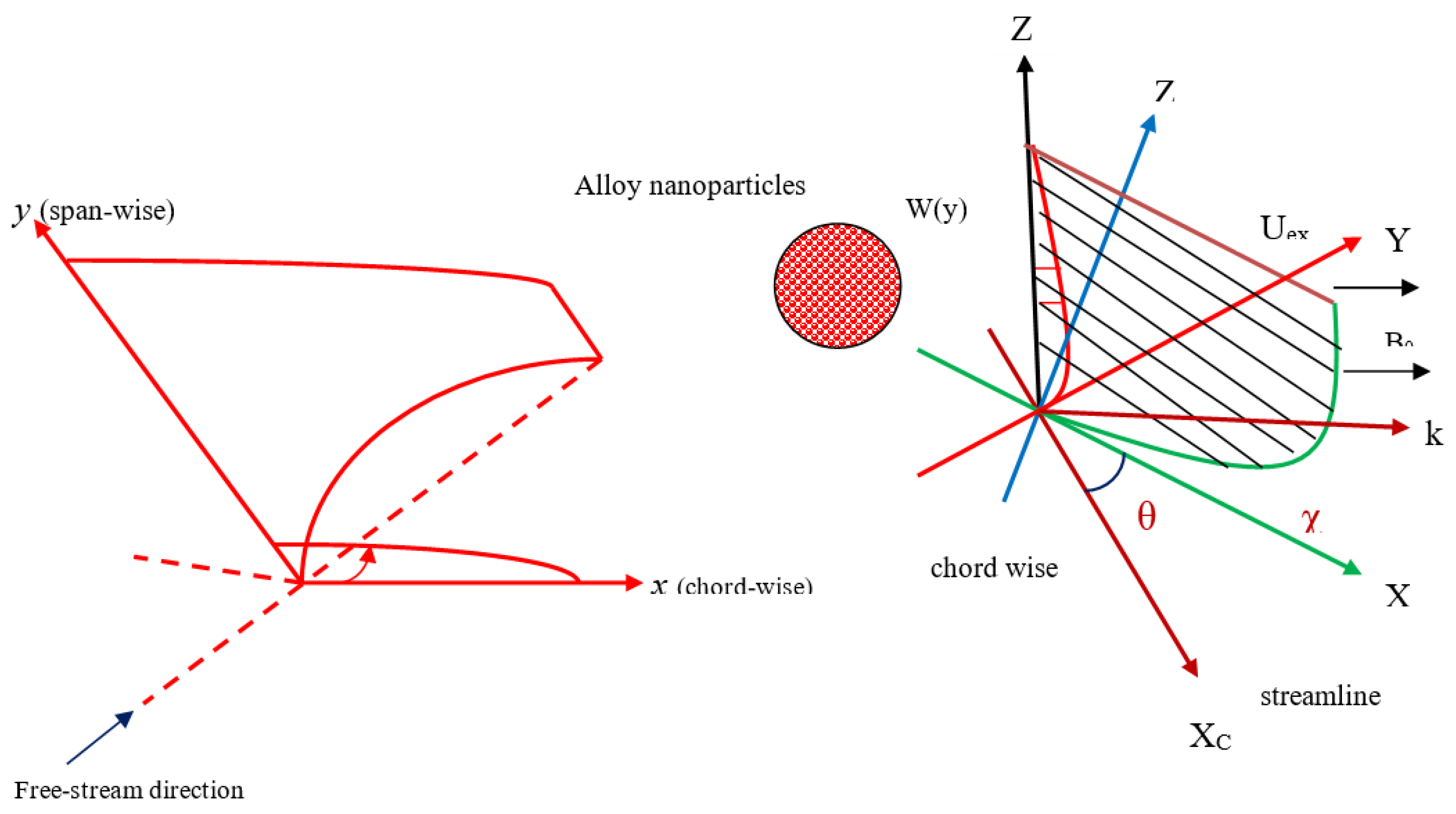
Figure 1. Physical diagram of the problem.
Crystals 10 00679 g001
Figure 2. Comparison of the velocity profile f ( η ) for λ .
Crystals 10 00679 g002
Figure 3. Influence of S on ( 2 Re x ) 1 / 2 C f x .
Crystals 10 00679 g003
Figure 4. Influence of S on ( 2 Re x ) 1 / 2 C f z .
Crystals 10 00679 g004
Figure 5. Influence of S on ( Re x / 2 ) 1 / 2 N u x .
Crystals 10 00679 g005
Figure 6. Influence of S on ( Re x / 2 ) 1 / 2 S h x .
Crystals 10 00679 g006
Figure 7. Influence of M on ( 2 Re x ) 1 / 2 C f x .
Crystals 10 00679 g007
Figure 8. Influence of M on ( 2 Re x ) 1 / 2 C f z .
Crystals 10 00679 g008
Figure 9. Influence of M on ( Re x / 2 ) 1 / 2 N u x .
Crystals 10 00679 g009
Figure 10. Influence of M on ( Re x / 2 ) 1 / 2 S h x .
Crystals 10 00679 g010
Figure 11. Influence of D u on ( Re x / 2 ) 1 / 2 N u x .
Crystals 10 00679 g011
Figure 12. Influence of D u on ( Re x / 2 ) 1 / 2 S h x .
Crystals 10 00679 g012
Figure 13. Influence of S r on ( Re x / 2 ) 1 / 2 N u x .
Crystals 10 00679 g013
Figure 14. Influence of S r on ( Re x / 2 ) 1 / 2 S h x .
Crystals 10 00679 g014
Figure 15. Influence of M on f ( η ) .
Crystals 10 00679 g015
Figure 16. Influence of M on g ( η ) .
Crystals 10 00679 g016
Figure 17. Influence of M on θ ( η ) .
Crystals 10 00679 g017
Figure 18. Influence of M on ϕ ( η ) .
Crystals 10 00679 g018
Figure 19. Influence of θ w on θ ( η ) .
Crystals 10 00679 g019
Figure 20. Influence of R d on θ ( η ) .
Crystals 10 00679 g020
Figure 21. Influence of S c on ϕ ( η ) .
Crystals 10 00679 g021
Figure 22. Influence of ϕ 1 , ϕ 2 on f ( η ) .
Crystals 10 00679 g022
Figure 23. Influence of ϕ 1 , ϕ 2 on g ( η ) .
Crystals 10 00679 g023
Figure 24. Influence of ϕ 1 , ϕ 2 on θ ( η ) .
Crystals 10 00679 g024
Figure 25. Influence of ϕ 1 , ϕ 2 on ϕ ( η ) .
Crystals 10 00679 g025
Table 1. Representation of the hybrid nanofluid properties [36].
PropertiesHybrid Nanofluid
Density ρ ^ h b n f = [ ϕ 2 ρ ^ s 2 + ( 1 ϕ 2 ) { ϕ 1 ρ ^ s 1 + ( 1 ϕ 1 ) ρ ^ f } ]
Viscosity μ ^ h b n f = μ ^ f ( 1 ϕ 2 ) 2.5 ( 1 ϕ 1 ) 2.5
Mass diffusivity D ^ h b n f = D ^ f ( 1 ϕ 1 ) ( 1 ϕ 2 )
Electrical conductivity σ ^ h b n f = σ ^ b f [ σ ^ s 2 ( 1 + 2 ϕ 2 ) + 2 σ ^ b f ( 1 ϕ 2 ) σ ^ s 2 ( 1 ϕ 2 ) + σ ^ b f ( 2 + ϕ 2 ) ]   with   σ ^ b f = σ ^ f [ σ ^ s 1 ( 1 + 2 ϕ 1 ) + 2 σ ^ f ( 1 ϕ 1 ) σ ^ s 1 ( 1 ϕ 1 ) + σ ^ f ( 2 + ϕ 1 ) ]
Thermal conductivity k ^ h b n f = k ^ s 2 + 2 k ^ nf 2 ϕ 2 ( k ^ n f k ^ s 2 ) k ^ s 2 + 2 k ^ nf + ϕ 2 ( k ^ n f k ^ s 2 ) × k ^ n f   with   k ^ n f = k ^ s 1 + 2 k ^ f 2 ϕ 1 ( k ^ f k ^ s 1 ) k ^ s 1 + 2 k ^ f + ϕ 1 ( k ^ f k ^ s 1 ) × k ^ f
Heat capacity ( ρ ^ c ^ p ) h b n f = [ ϕ 2 ( ρ ^ c ^ p ) s 2 + ( 1 ϕ 2 ) { ϕ 1 ( ρ ^ c ^ p ) s 1 + ( 1 ϕ 1 ) ( ρ ^ c ^ p ) f } ]
Table 2. Illustrates the features of the thermo-physical both nanoparticle and base fluid [39].
Thermo-Physical PropertiesH2O Aluminum   AA 7075 ( ϕ 1 ) Ti 6 Al 4 V   ( ϕ 2 )
ρ ^ 997.128104420
c ^ p 41799600.56
k ^ 0.61291737.2
σ ^ 0.0526.77 × 1065.8 × 105