Designer Synthesis of Ultra-Fine Fe-LTL Zeolite Nanocrystals

Abstract
:
1. Introduction
2. Materials and Methods
2.1. Materials
2.1.1. Synthesis of Zeolite L Precursor
2.1.2. Synthesis of Fe-L Samples
2.1.3. Synthesis of Conventional Fe-L Zeolite
2.2. Methods
3. Results and Discussion
4. Conclusions
Supplementary Materials
Author Contributions
Funding
Conflicts of Interest
References
- Davis, M.E.; Lobo, R.F. Zeolite and molecular sieve synthesis. Chemistry of Materials. Chem. Mater. 1992, 4, 756–768. [Google Scholar] [CrossRef]
- Gies, H.; Marler, B. The structure-controlling role of organic templates for the synthesis of porosils in the system SiO2/template/H2O. Zeolite 1992, 12, 42–49. [Google Scholar] [CrossRef]
- Davis, M.E. Ordered porous materials for emerging applications. Nature 2002, 417, 813–821. [Google Scholar] [CrossRef]
- Cundy, C.S.; Cox, P.A. The hydrothermal synthesis of zeolites: History and development from the earliest days to the present time. Chem. Rev. 2003, 103, 663–702. [Google Scholar] [CrossRef] [PubMed]
- Zou, X.; Conradsson, T.; Klingstedt, M.; Dadachov, M.S.; O’Keeffe, M. A mesoporous germanium oxide with crystalline pore walls and its chiral derivative. Nature 2005, 437, 716–719. [Google Scholar] [CrossRef] [PubMed]
- Ma, S.Q.; Sun, D.F.; Wang, X.S.; Zhou, H.C. A mesh-adjustable molecular sieve for general use in gas separation. Angew. Chem. Int. Ed. 2007, 46, 2458–2462. [Google Scholar] [CrossRef] [PubMed]
- Shin, J.; Camblor, M.A.; Woo, H.C.; Miller, S.R.; Wright, P.A.; Hong, S.B. PST-1: A synthetic small-pore zeolite that selectively adsorbs H2. Angew. Chem. Int. Ed. 2009, 48, 6647–6650. [Google Scholar] [CrossRef] [PubMed] [Green Version]
- Lee, J.H.; Park, M.B.; Lee, J.K.; Min, H.K.; Song, M.K.; Hong, S.B. Synthesis and characterization of ERI-type UZM-12 zeolites and their methanol-to-olefin performance. J. Am. Chem. Soc. 2010, 132, 12971–12982. [Google Scholar] [CrossRef]
- Na, K.; Jo, C.; Kim, J.; Cho, K.; Jung, J.; Seo, Y.; Messinger, R.J.; Chmelka, B.F.; Ryoo, R. Directing zeolite structures into hierarchically nanoporous architectures. Science 2011, 333, 328–332. [Google Scholar] [CrossRef] [PubMed] [Green Version]
- Zhang, X.Y.; Liu, D.X.; Xu, D.D.; Asahina, S.; Cychosz, K.A.; Agrawal, K.V.; Al Wahedi, Y.; Bhan, A.; Al Hashimi, S.; Terasaki, O.; et al. Synthesis of self-pillared zeolite nanosheets by repetitive branching. Science 2012, 336, 1684–1687. [Google Scholar] [CrossRef] [Green Version]
- Goel, S.; Wu, Z.J.; Zones, S.I.; Iglesia, E. Synthesis and catalytic properties of metal clusters encapsulated within small-pore (SOD, GIS, ANA) zeolites. J. Am. Chem. Soc. 2012, 134, 17688–17695. [Google Scholar] [CrossRef]
- Jo, C.; Jung, J.; Shin, H.S.; Kim, J.; Ryoo, R. Capping with Multivalent Surfactants for Zeolite Nanocrystal Synthesis. Angew. Chem. Int. Ed. 2013, 52, 10014–10017. [Google Scholar] [CrossRef]
- Moller, K.; Bein, T. Mesoporosity-a new dimension for zeolites. Chem. Soc. Rev. 2013, 42, 3689–3707. [Google Scholar] [CrossRef] [PubMed] [Green Version]
- Bian, C.Q.; Wang, X.; Yu, L.; Zhang, F.; Zhang, J.; Fei, Z.X.; Qiu, J.P.; Zhu, L.F. Generalized methodology for inserting metal heteroatoms into the layered zeolite precursor RUB-36 by interlayer expansion. Crystals 2020, 10, 530. [Google Scholar] [CrossRef]
- Song, W.; Justice, R.E.; Jones, C.A.; Grassian, V.H.; Larsen, S.C. Size-dependent properties of nanocrystalline silicalite synthesized with systematically varied crystal sizes. Langmuir 2004, 20, 4696–4702. [Google Scholar] [CrossRef] [PubMed]
- Larsen, S.C. Nanocrystalline zeolites and zeolite structures: Synthesis, characterization, and applications. J. Phys. Chem. C 2007, 111, 18464–18474. [Google Scholar] [CrossRef]
- Choi, M.; Na, K.; Kim, J.; Sakamoto, Y.; Terasaki, O.; Ryoo, R. Stable single-unit-cell nanosheets of zeolite MFI as active and long-lived catalysts. Nature 2009, 461, 246–249. [Google Scholar] [CrossRef]
- Eng-Poh, N.; Chateigner, D.; Bein, T.; Valtchev, V.; Mintova, S. Capturing ultrasmall EMT zeolite from template-free systems. Science 2012, 335, 70–73. [Google Scholar]
- Feng, G.D.; Cheng, P.; Yan, W.F.; Boronat, M.; Li, X.; Su, J.H.; Wang, J.Y.; Li, Y.; Corma, A.; Xu, R.R. Accelerated crystallization of zeolites via hydroxyl free radicals. Science 2016, 351, 1188–1191. [Google Scholar] [CrossRef] [Green Version]
- Chen, W.; Fan, Z.L.; Pan, X.L.; Bao, X.H. Effect of confinement in carbon nanotubes on the activity of Fischer-Tropsch iron catalyst. J. Am. Chem. Soc. 2008, 130, 9414–9419. [Google Scholar] [CrossRef]
- Awala, H.; Gilson, J.-P.; Retoux, R.; Boullay, P.; Goupil, J.-M.; Valtchev, V.; Mintova, S. Template-free nanosized faujasite-type zeolites. Nat. Mater. 2015, 14, 447–451. [Google Scholar] [CrossRef] [PubMed]
- Ohsuna, T.; Horikawa, Y.; Hiraga, K.; Terasaki, O. Surface Structure of Zeolite L Studied by High-Resolution Electron Microscopy. Chem. Mater. 1998, 10, 688–691. [Google Scholar] [CrossRef]
- Laulus, O.; Valtchev, V.P. Crystal morphology control of LTL-type zeolite crystals. Chem. Mater. 2004, 16, 3381–3389. [Google Scholar]
- Davis, R.J. Aromatization on zeolite L-supported Pt clusters. Heterogen. Chem. Rev. 1994, 1, 41–53. [Google Scholar]
- Joshi, P.N.; Bandyopadhyay, R.; Awate, S.V.; Shiralkar, V.P.; Rao, B.S. Influence of physicochemical parameters on n-hexane dehydrocyclization over Pt/LTL zeolites. React. Kinet. Catal. Lett. 1994, 53, 231–236. [Google Scholar] [CrossRef]
- Jentoft, R.E.; Tsapatsis, M.; Davis, M.E.; Gates, B.C. Platinum clusters supported in zeolite LTL: Influence of catalyst morphology on performance in n-hexane reforming. J. Catal. 1998, 179, 565–580. [Google Scholar] [CrossRef]
- Miller, J.T.; Agrawal, N.G.B.; Lane, G.S.; Modica, F.S. Effect of pore geometry on ring closure selectivities in platinum L-zeolite dehydrocyclization catalysts. J. Catal. 1996, 163, 106–116. [Google Scholar] [CrossRef]
- Barrer, R.M.; Galabova, I.M. Ion-exchanged forms of zeolite L, erionite, and offretite and sorption of inert-gases. Adv. Chem. Ser. 1973, 356–373. [Google Scholar] [CrossRef]
- Lee, T.P.; Saad, B.; Ng, E.P.; Salleh, B. Zeolite linde type L as micro-solid phase extraction sorbent for the high performance liquid chromatography determination of ochratoxin A in coffee and cereal. J. Chromatogr. A 2012, 1237, 46–54. [Google Scholar] [CrossRef]
- Calzaferri, G.; Huber, S.; Maas, H.; Minkowski, C. Host–Guest Antenna Materials. Angew. Chem. Int. Ed. 2003, 42, 3732–3735. [Google Scholar] [CrossRef]
- Gigli, L.; Arletti, R.; Tabacchi, G.; Fabbiani, M.; Vitillo, J.G.; Martra, G.; Devaux, A.; Miletto, I.; Quartieri, S.; Calzaferri, G. Structure and host-guest interactions of perylene-diimide dyes in zeolite L nanochannels. J. Phys. Chem. C. 2018, 122, 3401–3418. [Google Scholar] [CrossRef]
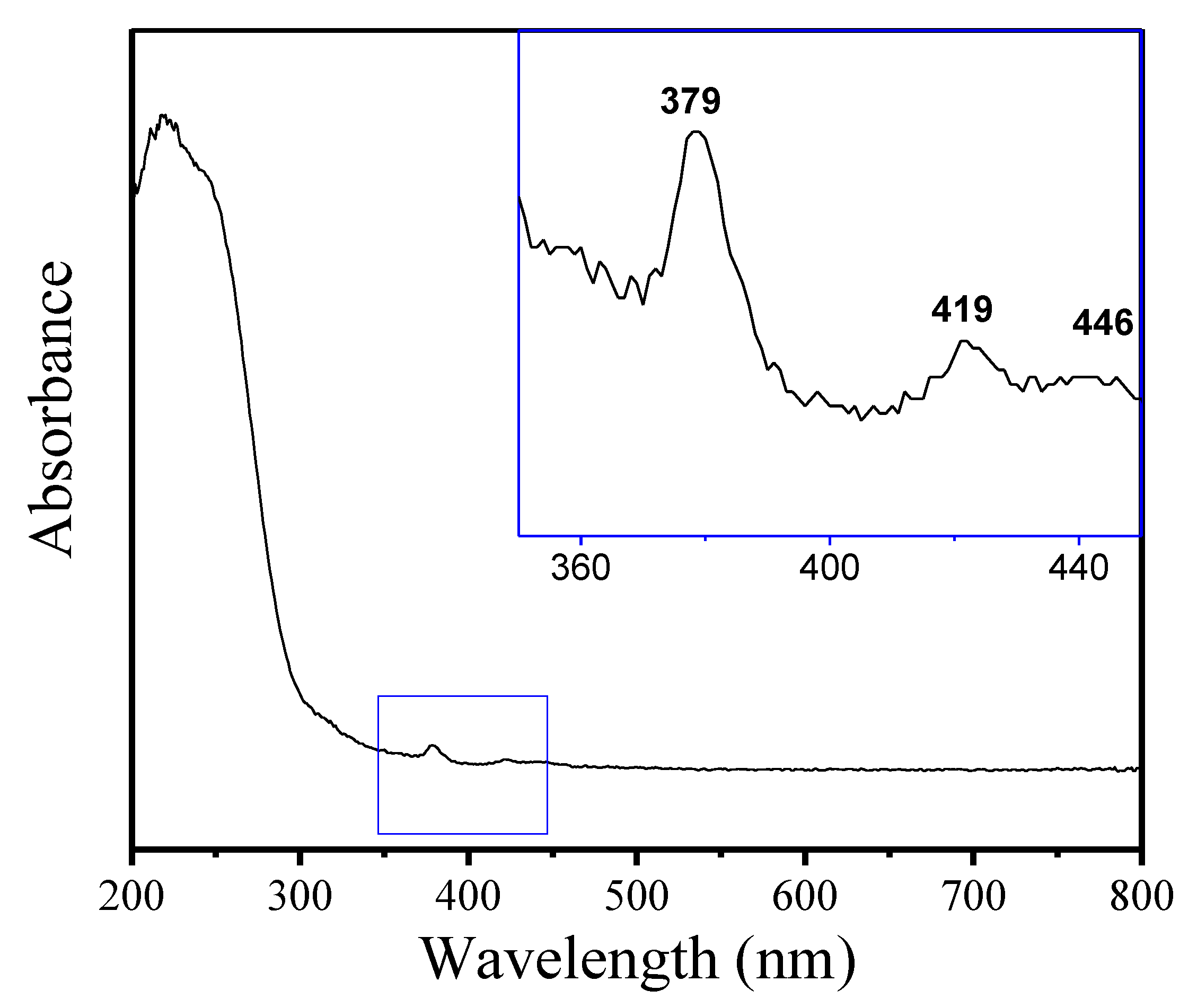
- Goldfarb, D.; Bernado, M.; Strohmaier, K.G.; Vaughan, D.E.W.; Thomann, H. Characterization of iron in zeolites by X-band and Q-band ESR, pulsed ESR, and UV-visible spectroscopies. J. Am. Chem. Soc. 1994, 116, 6344–6353. [Google Scholar] [CrossRef]
- Zhang, H.; Chu, L.; Xiao, Q.; Zhu, L.; Yang, C.; Meng, X.; Xiao, F.-S. One-pot synthesis of Fe-Beta zeolite by an organotemplate-free and seed-directed route. J. Mater. Chem. A 2013, 1, 3254–3257. [Google Scholar] [CrossRef]
- Camblor, M.A.; Corma, A.; Mifsud, A.; Perez-Pariente, J. Valencia, Synthesis of nanocrystalline zeolite Beta in the absence of alkali metal cations. Stud. Surf. Sci. Catal. 1997, 105, 341–348. [Google Scholar]

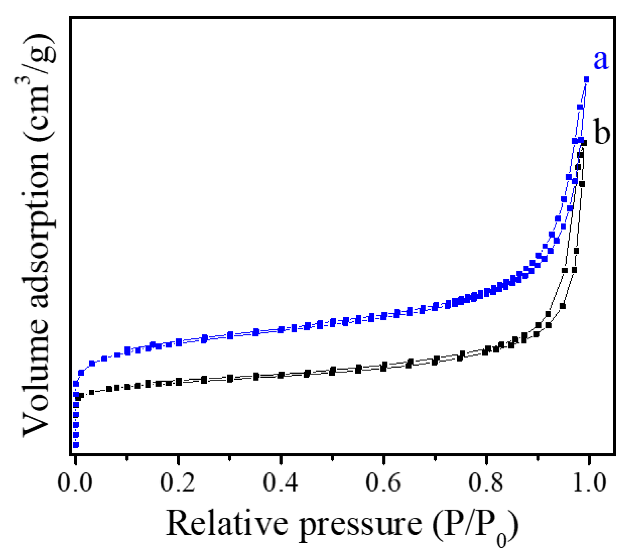
| Sample | SBET (m2g−1) | Smicro (m2g−1) | Vtotal (cm3g−1) | Vmicro (cm3g−1) |
|---|---|---|---|---|
| Fe-LTL-N | 285 | 228 | 0.38 | 0.10 |
| Fe-LTL-C | 142 | 128 | 0.19 | 0.12 |
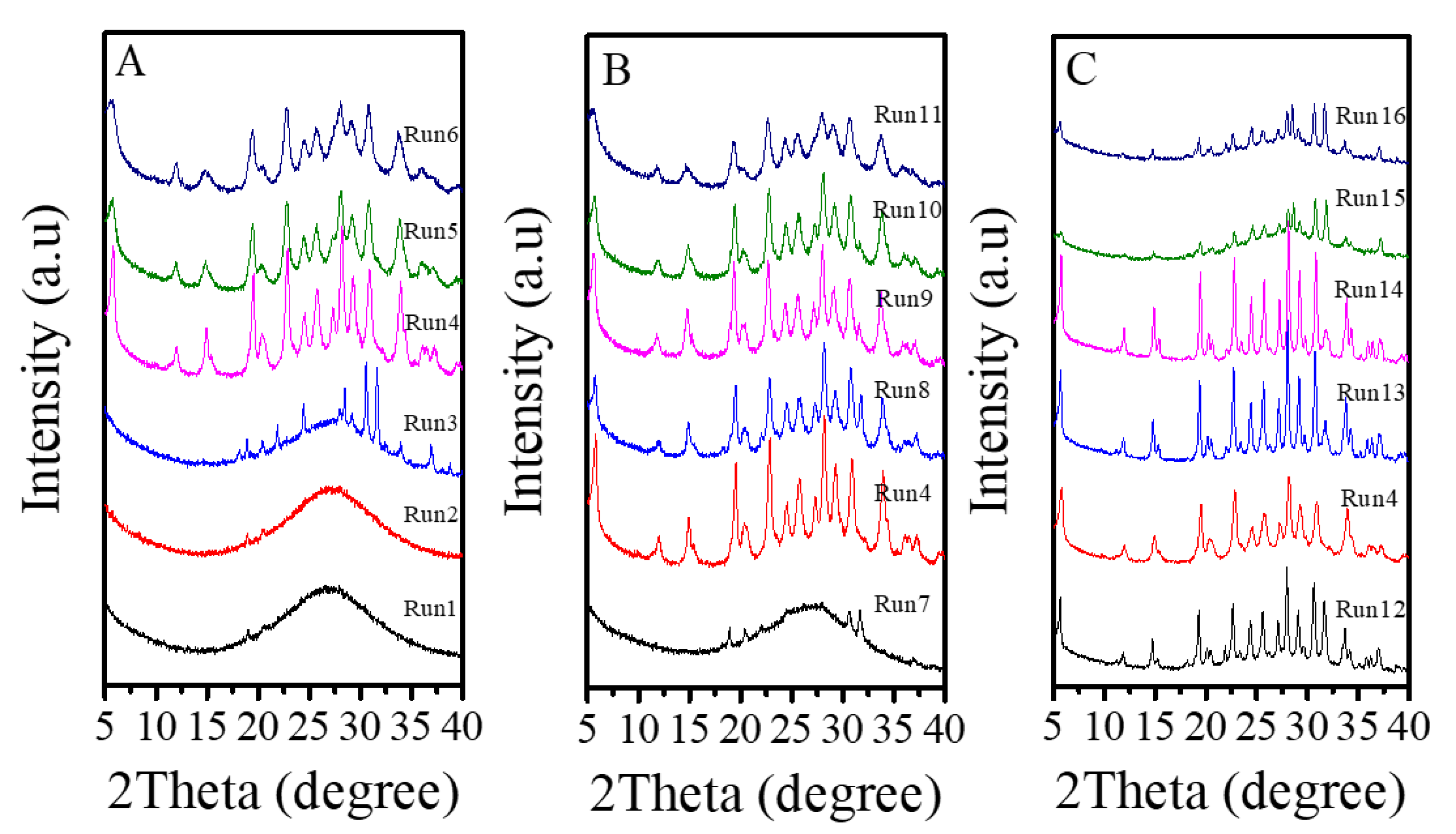
| Run | K2O/SiO2 | SiO2/Al2O3 | FeCl3/SiO2 | Product a | Crystallinity b (%) | Yield c (%) |
|---|---|---|---|---|---|---|
| 1 | 0.122 | 15 | 0.04 | Amor | / | / |
| 2 | 0.158 | 15 | 0.04 | Amor | / | / |
| 3 | 0.193 | 15 | 0.04 | Amor+LTL | / | / |
| 4 | 0.229 | 15 | 0.04 | LTL | 100 | 40 |
| 5 | 0.265 | 15 | 0.04 | LTL | 65 | 56 |
| 6 | 0.300 | 15 | 0.04 | LTL + Amor | / | / |
| 7 | 0.229 | 10 | 0.04 | Amor | / | / |
| 8 | 0.229 | 20 | 0.04 | LTL | 65 | 36 |
| 9 | 0.229 | 25 | 0.04 | LTL | 80 | 30 |
| 10 | 0.229 | 30 | 0.04 | LTL + Amor | / | / |
| 11 | 0.229 | 40 | 0.04 | LTL + Amor | / | / |
| 12 | 0.229 | 15 | 0.03 | LTL | 100 | 30 |
| 13 | 0.229 | 15 | 0.05 | LTL | 100 | 67 |
| 14 | 0.229 | 15 | 0.06 | LTL | 100 | 72 |
| 15 | 0.229 | 15 | 0.07 | LTL + Amor | / | / |
| 16 | 0.229 | 15 | 0.08 | LTL + Amor | / | / |
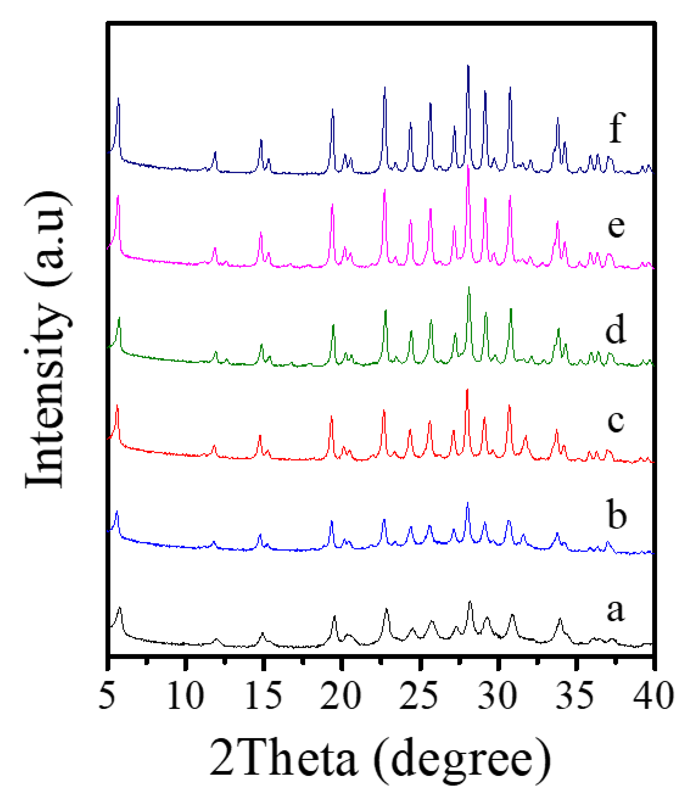
| Run | Fe/Si Ratio in the Initial Gel | Fe Content in the Obtained Sample d | Si/Al Ratio in the Obtained Sample d |
|---|---|---|---|
| 12 | 0.03 | 2.07% | 4.6 |
| 4 | 0.04 | 2.67% | 4.7 |
| 13 | 0.05 | 3.33% | 4.6 |
| 14 | 0.06 | 3.10% | 5.3 |
| 15 | 0.07 | 3.74% | 5.8 |
| 16 | 0.08 | 3.34% | 5.9 |
© 2020 by the authors. Licensee MDPI, Basel, Switzerland. This article is an open access article distributed under the terms and conditions of the Creative Commons Attribution (CC BY) license (http://creativecommons.org/licenses/by/4.0/).
Share and Cite
Zhang, F.; Luo, Y.; Chen, L.; Chen, W.; Hu, Y.; Chen, G.; You, S.; Song, W. Designer Synthesis of Ultra-Fine Fe-LTL Zeolite Nanocrystals. Crystals 2020, 10, 813. https://doi.org/10.3390/cryst10090813
Zhang F, Luo Y, Chen L, Chen W, Hu Y, Chen G, You S, Song W. Designer Synthesis of Ultra-Fine Fe-LTL Zeolite Nanocrystals. Crystals. 2020; 10(9):813. https://doi.org/10.3390/cryst10090813
Chicago/Turabian StyleZhang, Fen, Yunhong Luo, Lei Chen, Wei Chen, Yin Hu, Guihua Chen, Shengyong You, and Weiguo Song. 2020. "Designer Synthesis of Ultra-Fine Fe-LTL Zeolite Nanocrystals" Crystals 10, no. 9: 813. https://doi.org/10.3390/cryst10090813