Article

Influence of Milling Route on the Corrosion Passivation of Al-2%SiC Nanocomposites in Chloride Solutions

1
Centre of Excellence for Research in Engineering Materials, King Saud University, P.O. Box 800, Riyadh 11421, Saudi Arabia
2
Mechanical Engineering Department, Collage of Engineering, King Saud University, P.O. Box 800, Riyadh 11421, Saudi Arabia
3
Mechanical Design and Materials Department, Faculty of Energy Engineering, Aswan University, Aswan 81521, Egypt
*
Authors to whom correspondence should be addressed.
Crystals 2021, 11(10), 1231; https://doi.org/10.3390/cryst11101231
Submission received: 20 September 2021 / Revised: 5 October 2021 / Accepted: 9 October 2021 / Published: 12 October 2021
(This article belongs to the Special Issue Advances in Nanocomposites and Alloys in Saudi Arabia)

Abstract

:
In this work, the fabrication of three Al-2wt.% SiC nanocomposites processed by novel milling route was carried out. The beneficial influence of milling route on the corrosion passivation of the new fabricated composites was investigated. The cyclic polarization measurements have proved that increasing the time of ball milling highly reduced the corrosion of Al-SiC nanocomposite via reducing obtained corrosion current and so increasing the corrosion resistance. These results were affirmed by the electrochemical impedance spectroscopy experiments. The pitting corrosion of the manufactured composites was also reported, and its intensity decreased with the increase of ball milling time. The electrochemical experiments were also performed after expanding the exposure time in the chloride solution to 24 and 48. It was found that both the uniform and pitting corrosion decrease with prolonging the time. The study was complemented by examining the surface morphology and the elemental analyses for the different composites by using surface analyses techniques.

1. Introduction

Aluminum and its composites are employed in numerous structural purposes in our daily life. These applications such as in automotive and aerospace industries [1,2,3,4]. The lightweight, good fatigue strengths improved mechanical properties and high wear resistance are the main reason for the use of these materials in such applications. Due to these various applications, the corrosion behavior in aggressive media is very important for Al-based composites [5,6,7,8,9]. Some researchers [4,5,6] have reported that the reinforcement particulates may accelerate the corrosion of the Al-based alloys due to their electrochemically interaction with the matrix of the composite. The addition of some reinforcements may also lead to decreasing the corrosion resistance as a result of the occurrence of galvanic interactions between those reinforcements. Other forms of corrosion such as preferential and localized (crevice and pitting) corrosion can also take place, which would limit the application of some Al-based alloys [7,8,9].
Considerable works have been also carried out on the corrosion of Al composites in corrosive environments such as sodium chloride solutions including the reporting of the effect of nano-ceramic additives [10,11,12,13,14,15,16,17,18]. The corrosion susceptibility, pitting potential and pitting morphology of Al matrix composites in the chloride (NaCl) solutions were also reported [14,15,16,17,18]. The corrosion of grade A356 Al alloy that was reinforced with nano- Al2O3 particulates in 3.5% NaCl solution has been reported [11]. The microstructural and corrosion behavior of Al/SiC composite in 3.5% NaCl solution at different temperatures was also reported by H. M. Zakaria [19]. It was found that the reported Al/SiC MMCs show higher corrosion resistances when exposed to the chloride solutions at ambient temperature when compared to pure Al matrix and this effect increases when the particle size of SiC is reduced and/or the volume fraction of the SiC particles increases [19]. The effect of mechanical milling on the corrosion behavior of Al-Zn/Al2O3 composite in 3.5% NaCl solution using potentiodynamic polarization technique has been also reported [12]. It was found that milling the Al-Zn/Al2O3 composite increases the resistance towards corrosion of the composite as compared to the same composite without milling [11]. The processing method for the fabrication of the Al-based MCCs has been reported to affect and alter the microstructure as well as the corrosion resistance [17,18,19].
The objective of this research work was to manufacture Al-2%SiC composites that was processed at three different ball milling routes. The objective was also extended to investigate the corrosion behavior of the manufactured composites after 1 h, 24 h, and 48 h exposure in 3.5% NaCl solutions using various electrochemical and spectroscopic techniques. It is expected that the change of milling route will positively alter the corrosion resistance of Al-2%SiC composites.

2. Experimental Part

2.1. Chemicals, Materials, and Fabrication of Al-SiC Composites

Three aluminum metal matrixes reinforced with 2 wt.% SiC nanoparticles were synthesized via different powder metallurgy routes. The fabrication of these three nanocomposites has been reported in the previous study [20]. In brief, the three routes have similar first and second ball milling stages and differ in the third stage as summarized in Table 1. Where in the first stage and for all nanocomposites, the 98 wt% Al powder was mixed with the 2 wt% SiC nanoparticles, which were ball milled under a rotating speed of 150 rpm for 8 h before being ball milled again at a speed of 300 rpm for 4 h. The first nanocomposite was obtained after the first stage and was not processed any further. The second nanocomposite was obtained after being ball milled again at 150 rpm speed for another two hours. The third nanocomposite was processed further to be ball milled at a rotating speed of 450 rpm for 1 h.
The synthesized nanocomposites powders were consolidated using high-frequency induction heat sintering furnace (HFIHS) from ELTek Co., Gyeonggi-do, South Korea. In this consolidation process, compaction and sintering are conducted simultaneously in 5 min. In HFIHS, the temperature is generally held approximately 20% lower than the solidus temperature of the base materials being processed 570 °C, in current study. The 10 mm graphite die is filled with ball milled powder, closed by two punches from each side, and placed in an evacuated chamber. A uniaxial pressure of 40 MPa is applied through the sintering process. The required heat for the sintering process is generated at 150 °C/min by applying a strong magnetic field.

2.2. Electrochemical Experiments

A three electrodes electrochemical cell of a 0.3 L NaCl solution was used. Al-SiC nanocomposites rods, a platinum (Pt) sheet, and a silver/silver chloride (Ag/AgCl) electrode were served as working, counter, and reference electrodes. The working electrodes were gotten ready for electrochemical measurements [21,22,23,24]. The Al-SiC electrodes were surface finished before being immersed in the chloride test solution as reported in our previously published work [21,22]. The Model PGSTAT-302N Autolab Potentiostat was used for the polarization, impedance, and potentiostatic current-time at constant voltage value experiments. The polarization curves were measured between a potential range from −1400 to −200 mV, where the potential was swept from the more negative (−1400 mV) towards the less negative direction with applying a scan rate 0.00166 V/s. The potentiostatic current-time (PCT) at a value of −500 mV vs. Ag/AgCl runs were obtained for all Al-SiC nanocomposites over 40 min. Electrochemical impedance spectroscopy (EIS) data were obtained at the open-circuit potential values as described in the recent studies [21,22]. All experiments were measured for the nanocomposites after 1, 24, and 48 h in the 3.5% NaCl test solution, and 25 °C ± 3 surrounding temperature.

2.3. Surface Analyses Techniques

The newly manufactured nanocomposites were characterized by the powerful X-ray diffraction (XRD) method. The XRD patterns were collected via employing a D-8 Discover diffractometer to identify the phase analysis. The XRD patterns were obtained at 2°/min scan rate, 10 to 90° angle range, and 0.02° a locked scan type as an increment. More details about XRD results can be found in the earlier investigation [20]. The SEM and the EDX analyses were also investigated.

3. Results and Discussion

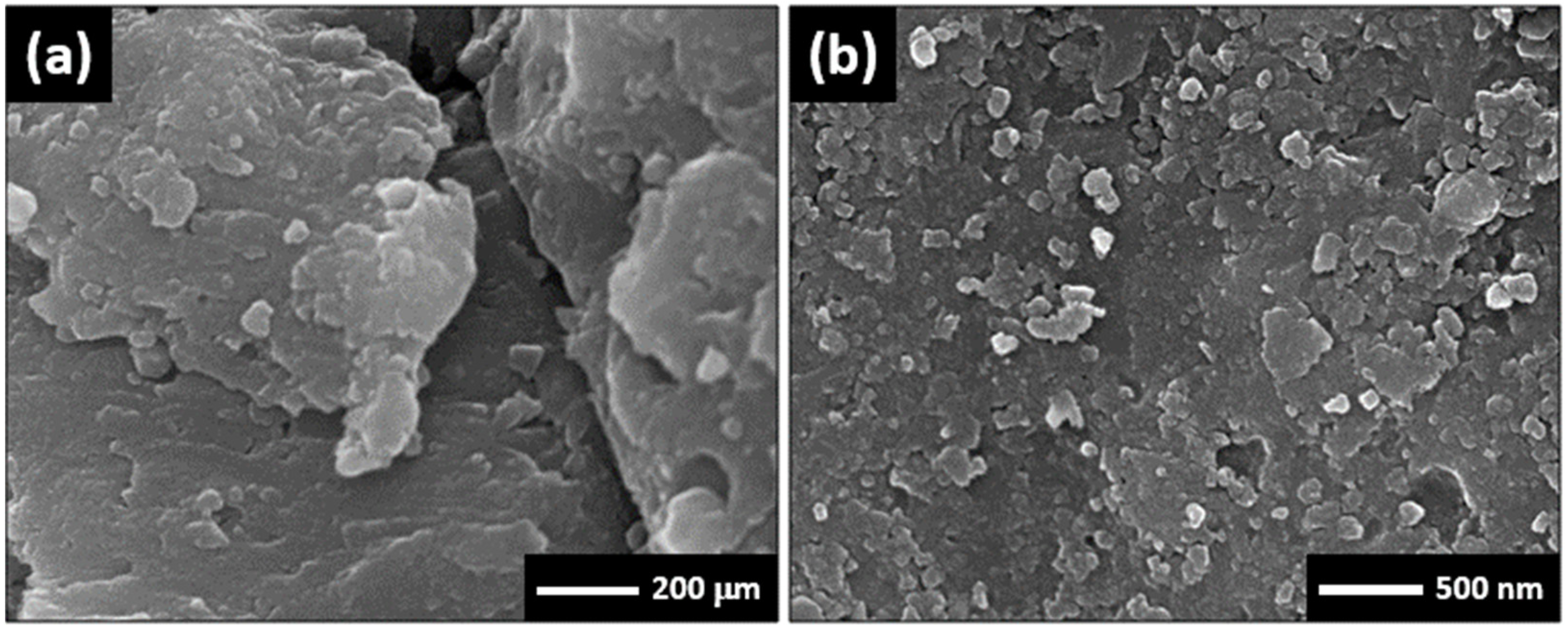
3.1. Morphology and X-ray Investigations

The morphological analysis can help investigate the manner in which the reinforcement is distributed, and the size of the particles, which play a very important role in understanding how to achieve enhanced electrochemical behavior in the produced composite. From this point of view, Figure 1 shows the morphology of the ball milled powder representing the third designed route in this study.
The XRD patterns for the bulk of 1st Al-SiC nanocomposite, 2nd Al-SiC nanocomposite and 3rd Al-SiC consolidated nanocomposite is shown in Figure 2. It is indicated from the XRD patterns that the presence of SiC phase peaks could be identified for all the fabricated nanocomposites. Where, the obtained patterns confirm the presence of SiC peaks in all samples at 35.5°; (111), 62.6°; (220) and 75.8°; (222) in addition to Al peaks for the base matrix. Moreover, the upper pattern, which represents the bulk of the third Al-SiC nanocomposite, has diminished intensity and broadened peaks in comparison with the collected patterns for the first and the second Al-SiC nanocomposites. From the patterns, the third route the supreme diminished and maximum broadening peaks, confirming the minimum crystallite size and lowest dislocation density. The higher grain refinement obtained in particular for the third nanocomposite has resulted from the long ball milling time that was given to that nanocomposite. The effectiveness of the route was guaranteed in limiting the growth of grains leading to the prevention of dislocation movement, which results in better corrosion resistance.

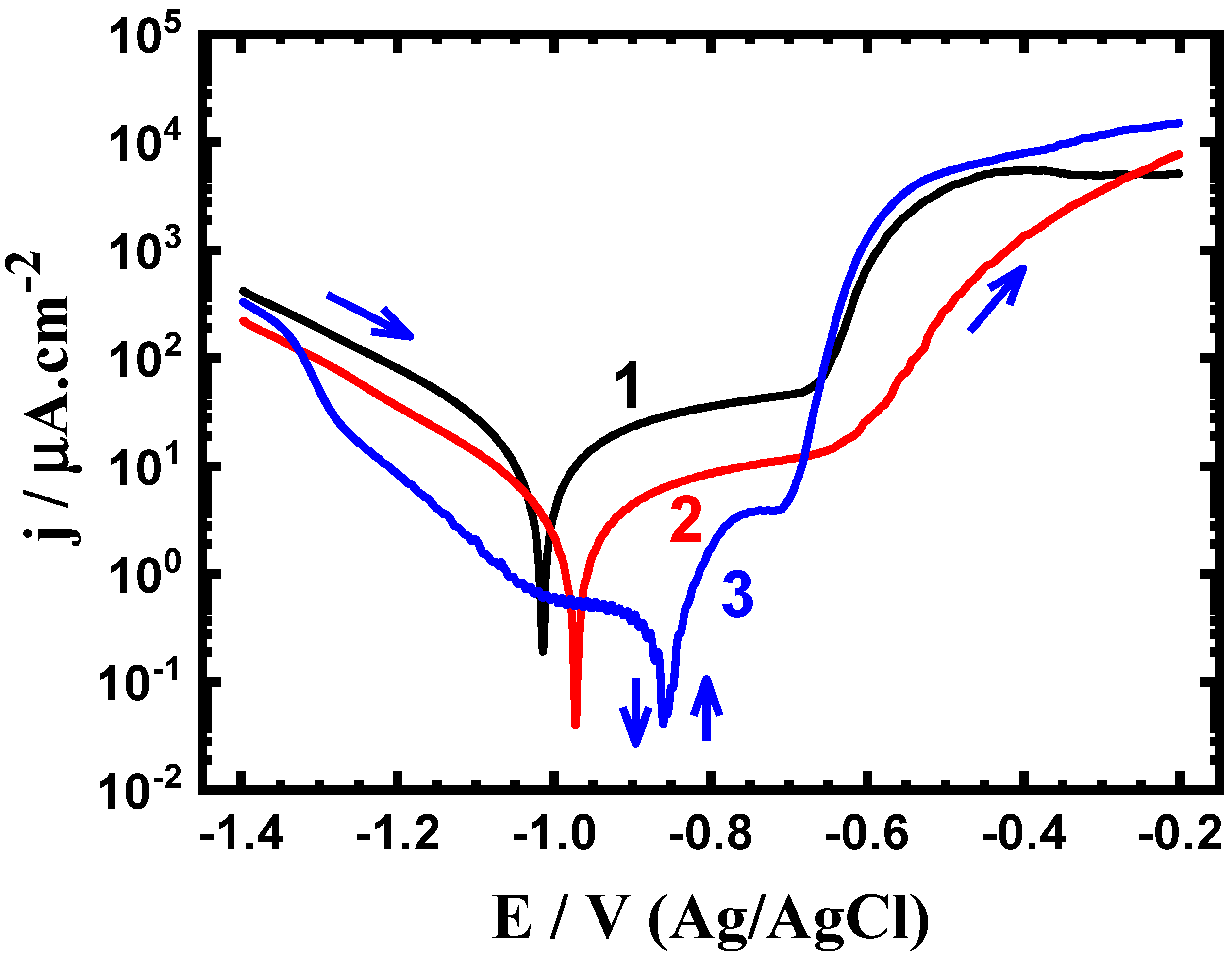
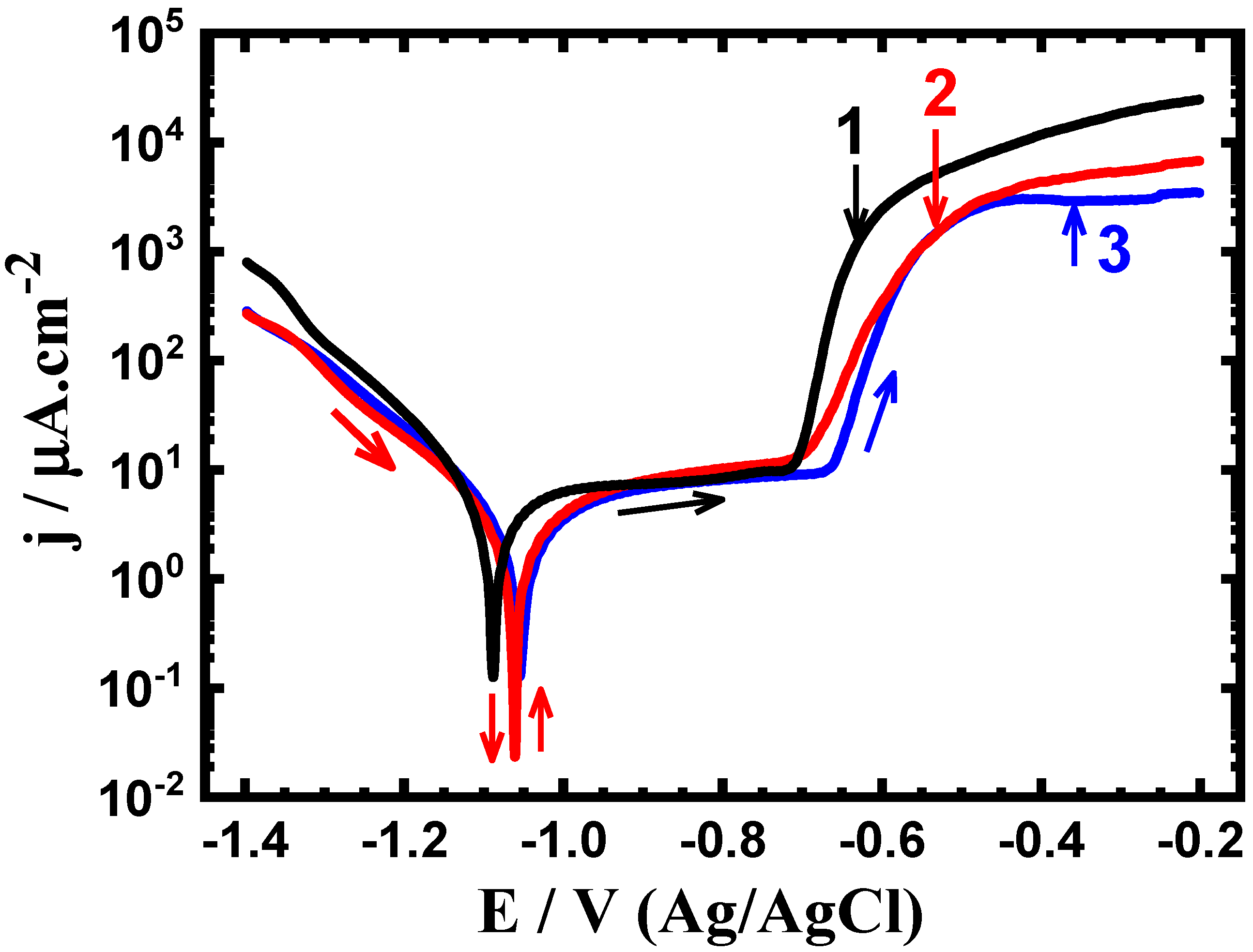
3.2. Potentiodynamic Polarization Data

The potentiodynamic polarization curves of the Al-2%SiC nanocomposites, (1) first nanocomposite, (2) second nanocomposite, and (3) third nanocomposite obtained after 1 h exposure in the test solution are displayed in Figure 3. The same measurements were also obtained after increasing the immersion time to 24 h and 48 h and the curves are depicted in Figure 4; Figure 5, respectively. The corrosion parameters obtained from the polarization curves are tabulated in Table 2. These parameters are the cathodic (βc) and anodic (βc) Tafel slopes, corrosion potential (ECorr), corrosion current density (jCorr), and pitting potential (EPit), were obtained as previously reported [22,23,25,26]. The corrosion resistance (RP) and corrosion rate (RCorr) were respectively calculated according to the following equations [25,26,27]:
R P = 1 j Corr   ( β c · β a 2.3 ( β c + β a ) )
R Corr =   j Corr ( k · E W d · A )
Here, k is a constant (to define the unit for RCorr, k = 3272 mm (amp−1 cm−1 year−1)), EW is the equivalent weight (EW = 9 g equivalent), d is the density (d = 2.7 gm cm−3), and A is the area of the surface (A = 1 cm2).
The current obtained for all nanocomposites decreased with the increase of potential to reach the values of jCorr and ECorr. The current then increases with the increase of potential in the anodic direction. The cathodic reaction here is the oxygen reduction via the following equations [28,29,30]:
2 H 2 O + O 2 + 4 e = 4 OH
1 2 O + H 2 O + 2 = 2 OH  
OH ads + e = OH
The potentiodynamic measurements for the two nanocomposites exhibit active-passive curves. The active region, where the current increases rapidly because of the dissolution of Al via this reaction:
Al = Al3+ + 3e
The passive region results from the adsorption of the hydroxide ions that were produced from the cathodic reaction of Al-SiC nanocomposite [27,28,29,30]:
Al ( S ) + 3 OH = Al ( OH ) 3 , ads + 3 e
This Al(OH)3 is unstable and is transferred into Al 2 O 3 · 3 H 2 O as follows [31]:
2 Al ( OH ) 3 , ads = Al 2 O 3 · 3 H 2 O
Further increasing the potential in the less negative direction led to sudden increase in the values of current due to the breakdown of the oxide layer (Equation (8)) and the occurrence of pitting corrosion. The effect of increasing the ball milling time on the polarization behavior of the Al-SiC Nanocomposite 2 recorded provided lower cathodic and anodic currents and lower values of jCorr and RCorr as well as less negative ECorr and higher RP values as can be seen from Figure 3 and Table 2. This was more clear when the ball milling was further increased, where Nanocomposite 3 recorded the lowest jCorr and RCorr and the lowest RP. Prolonging ball milling time thus increases the corrosion resistance of the Al-SiC nanocomposite via decreasing its uniform and pitting corrosion.
The curves obtained after 24 h as seen in Figure 4 show that prolonging time of expsoure before the test reduces the corrosion due to decreasing the values of jCorr. The increase of ball milling time (curve 2) is very effetive in decreasing the uniform corrosion via greatly reducing the jCorr and RCorr values. The third nanocomposite presented the best corrosion resistance and this confirms that increasing ball milling time improves the resistance for corrosion of the Al-SiC nanocomposite. Moreover, prolonging the immersion time has show an effictive parameter when the polarization measurements were obtained after 48 h (Figure 5). Where, these nanocomposites recorded the lowest values for the anodic, cathodic, the values of jCorr and the values of RCorr. This was also reflected on the value of pitting potential (EPit, Table 2), which is shifted to the less negative values. Furthermore, the values of RP were the highest for Nanocomposite 3 after its immersion for 48 h, which confirms that the increase of ball milling time as well as the immersion time enhances the corrosion resistance of Al-Sci nanocomposite.

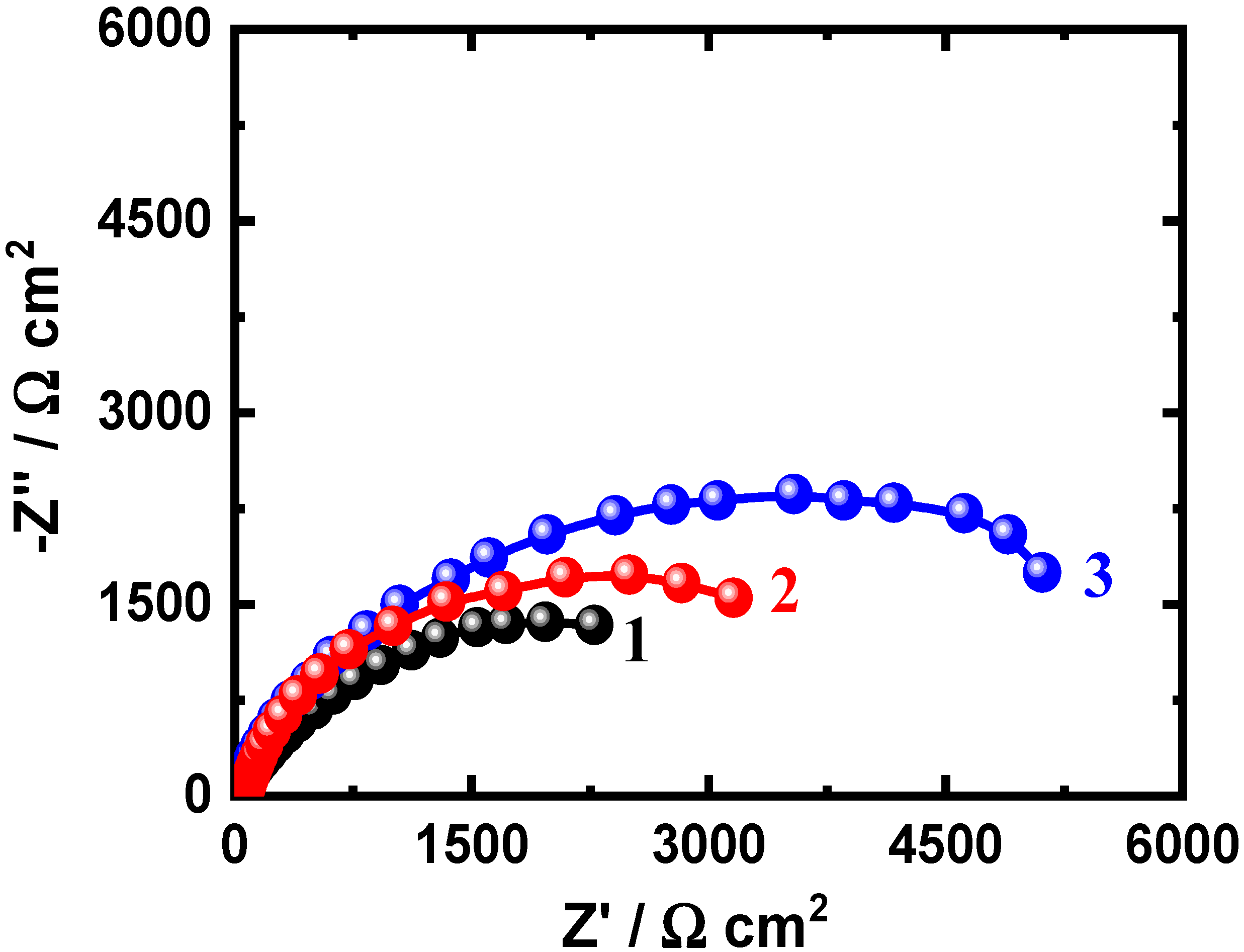
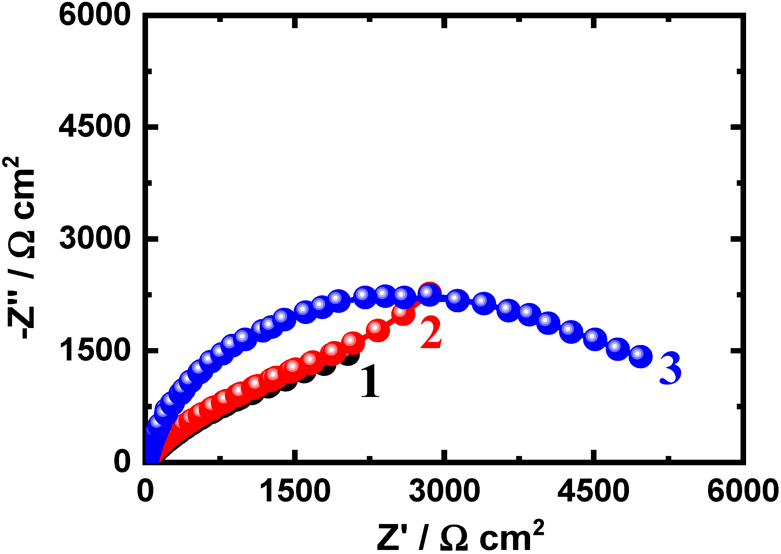
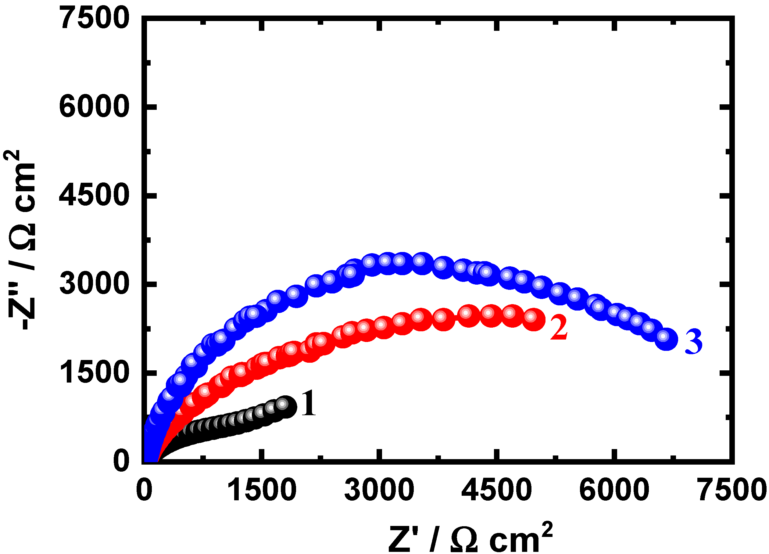
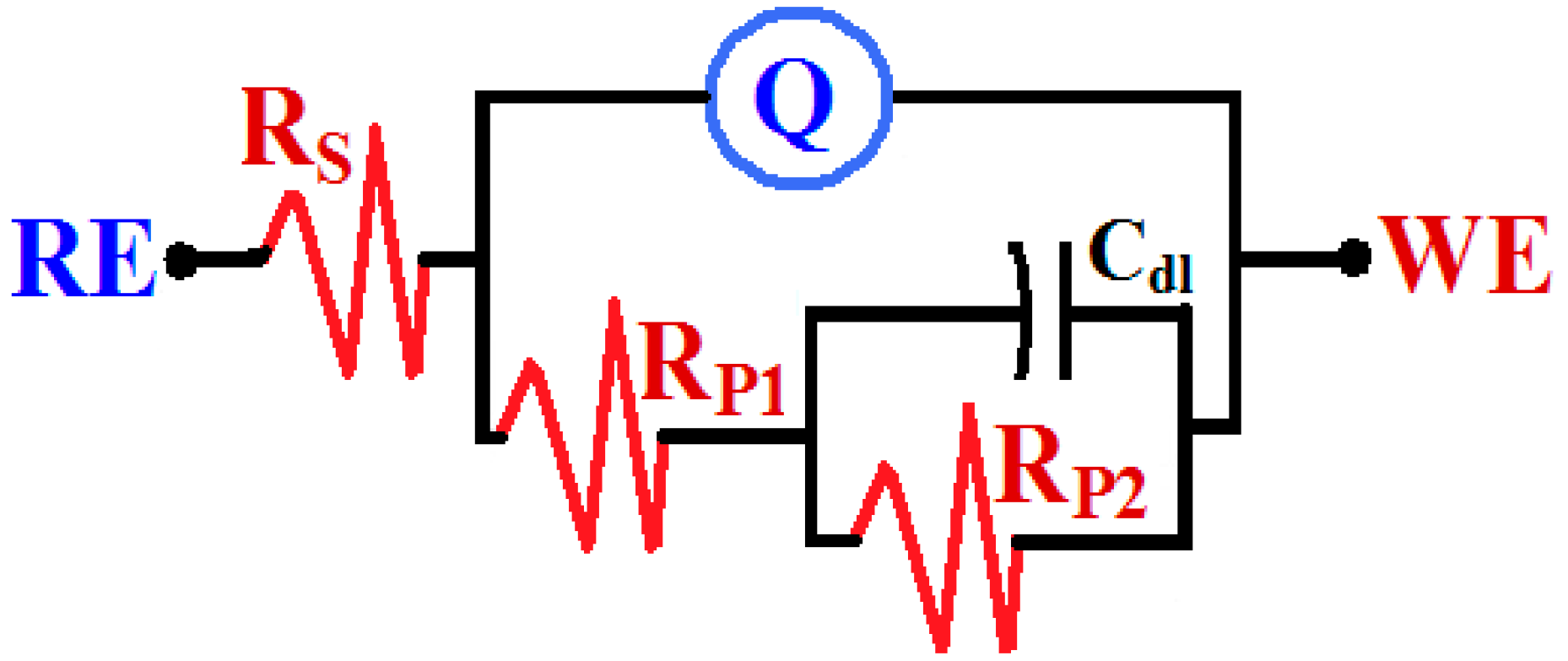
3.3. EIS Measurements

The plots of the Nyquist spectra obtained for Al-2%SiC nanocomposites, (1) Nanocomposite 1, (2) Nanocomposite 2, and (3) Nanocomposite 3, which were immersed in 3.5% NaCl solutions for 1 h are shown in Figure 6. Typical measurements were collected after 24 h and 48 h and the impedance plots are displayed respectively in Figure 7 and Figure 8. All EIS data were fitted to a circuit and the best equivalent is depicted in Figure 9. As can be seen that the circuit has a solution resistance (RS), two polarization resistances (RP1 and RP2), constant phase elements Q (YQ, CPEs), and a double layer capacitor (Cdl). These parameters are listed collectively in Table 3. The impedance, admittance of a CPE and the Q itself at this condition may be defined as follows:
ZCPE = −(1/Y0)(jω)n
YCPE = −Y0(jω)n
ZCPE = [Q(2πfi)n]−1
The plots seen in Figure 6 for the Al-SiC nanocomposites show only one semicircle whose diameter is increasing with the increase of ball milling time. The listed values in Table 3 along with the semicircle of the Nyquist plots indicate that the values of all resistances (RS, RP1, and RP2) are increasing with the ball milling time. In addition, the anodic films are composed of two formed layers having a complex structure as indicated by the presence of different time constants in the circuit model shown in Figure 9. These layers are an inner layer and another outer one. The inner layer is dominating impedance at high frequency area, while the outer layer (porous layer) is dominating at low frequency range [32,33]. Further, Q (with its “n” value is circa 1) is considered as double layer capacitors, which gives a confirmation that the outer layer has some porosities and is dominating the impedance at the low-frequency region [20,26]. In addition, the presence of a Cdl reveals that prolonging ball milling time enhances the passivation of the surface against corrosion in the chloride solutions. This claim was further supported by the increase of all resistances and the decrease of both YQ and Cdl values with the increase of the time of ball milling of the nanocomposites.
The Nyquist spectra were also collected after 24 h and 48 h as depicted in Figure 7; Figure 8, respectively. These EIS data indicated that the increase of exposure time increases the diameter of the plotted semicircle for all nanocomposites. This was further confirmed by the parameters depicted in Table 3. Where, the values of Rs, RP1 and RP2 are increasing when the time of immersion is increasing from 1 h to 24 h and further to 48 h. This effect also was found to decrease the values of YQ and Cdl. The impedance data thus confirm that the increase of the time of ball milling in addition to prolonging the time of exposure increase the corrosion resistance for the Al-SiC nanocomposite, which agrees also with the polarization results.

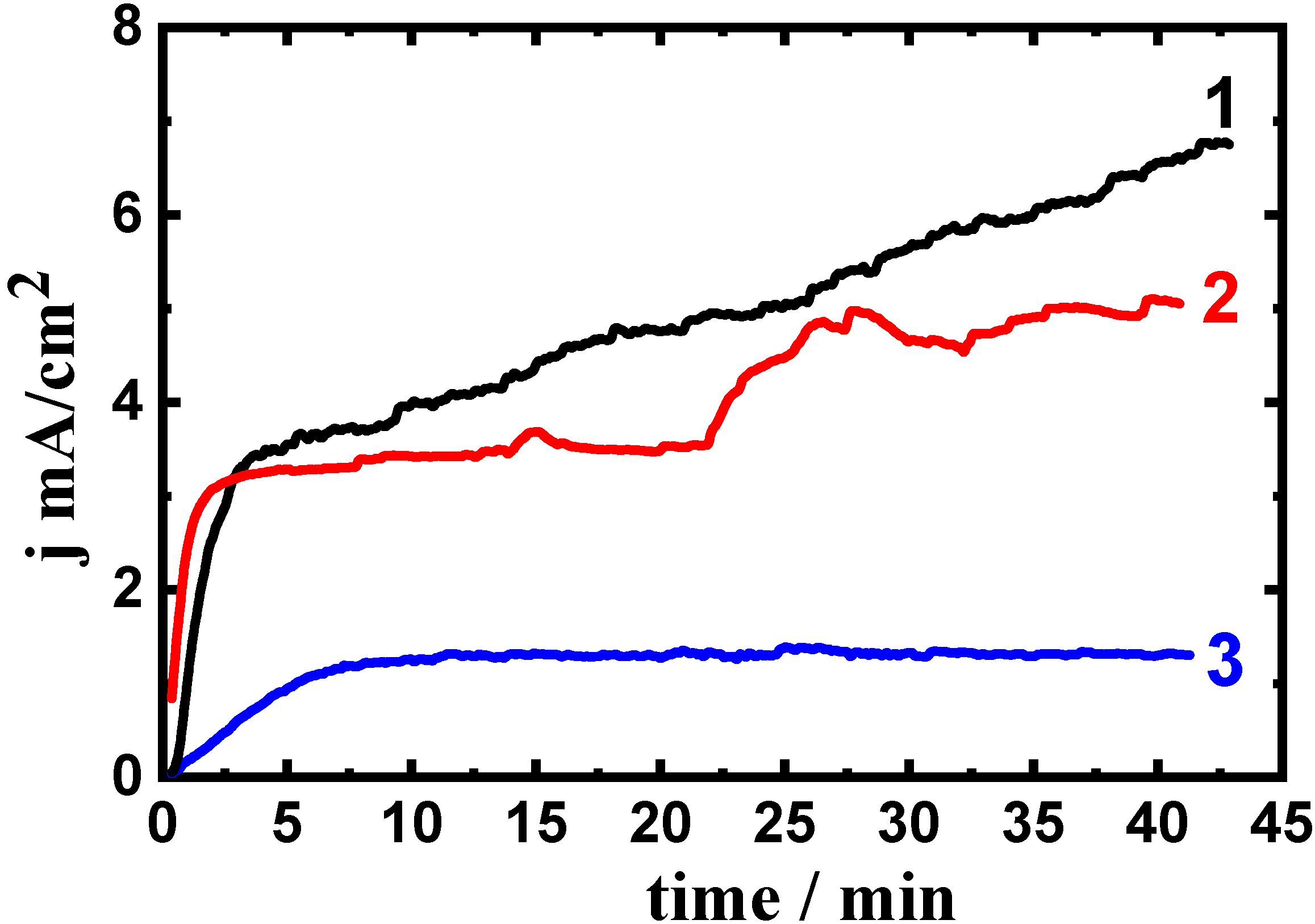
3.4. Current-Time Measurements

The potentiodynamic current-time (PCT) measurements at −500 mV (Ag/AgCl) for (1) first Al-SiC alloy, (2) second Al-SiC nanocomposite and (3) third Al-SiC nanocomposite after 1 h in NaCl solutions are shown in Figure 10. The PCT measurements were also obtained after 24 h and 48 h as depicted respectively in Figure 11 and Figure 12. The current of the PCT curves for all nanocomposites seen in Figure 10 increase upon the application of the −500 mV in the first few moments. The initial increase of current with increasing time is most probably due to the dissolution of an oxide film that was formed during the immersion of the nanocomposites in the chloride solutions before applying the constant potential.
The obtained PCT for the first nanocomposite continue increasing with time but this increase slows down with prolonging the time till the end of the run. This behavior is due to the dissolution of Al that is in the nanocomposite according to the aforementioned reaction (Equation (6)). The continuous increase of current for the first nanocomposite is due to the occurrence of pitting corrosion as a result of the attack of the chloride solution towards the surface of the nanocomposite and the formation of aluminum chloride complex, AlCl4, which diffuses into the balk solution [17,25,26,34,35,36,37,38,39]:
Al3+ + 4Cl = AlCl4
Al + 4Cl = AlCl4 + 3e
One other opinion suggested [29,34,35] that Cl ions are chemisorbed onto the oxide film on the nanocomposite’s surface, allowing the oxide to dissolve through oxychloride complexes formation:
Al + 2Cl + 2OH = Al(OH)2Cl2
The highest absolute currents obtained for (in addition to the occurrence of pitting corrosion) the first nanocomposite (curve 1, Figure 10), also prove that this nanocomposite surfers also high uniform corrosion at the applied potential, −500 mV (Ag/AgCl). The currents obtained for the second nanocomposite after 1 h exposure (curve, Figure 10) showed lower absolute current values over the whole time of the experiment. This suggests that the second nanocomposite also suffers pitting corrosion but its uniform corrosion is lower as compared to the first nanocomposite. On the other hand, the third nanocomposite showed a brut decrease of current after about 5 min of applying the potential, which reveals that the pits that are resulting from the increase of current may have blocked and not propagated. The PCT curves obtained by Figure 10 thus indicate that the third nanocomposite has higher corrosion resistance towards both pitting and uniform corrosion.
Increasing the time of exposure to 24 h, Figure 11 slowed down the initial increase of currents as a result of the oxide film thickening during the immersion of the nanocomposites before measurements. The current continues increasing with time for all nanocomposites till the end of the experiment, which confirms the occurrence of pitting corrosion. The absolute current is seen to be higher for the first nanocomposite and decreases in the following order: first nanocomposite > second nanocomposite > third nanocomposite. The intensity of corrosion of the fabricated nanocomposites is thus the highest for the first nanocomposite and decreases in the aforementioned order.
Prolonging the exposure periods to 48 h as seen in Figure 12 has provided almost the same PCT behavior similar to the PCT data after 24 h immersion (Figure 11) except that the values of current with time were lower for all nanocomposites. The effect of prolonging the immersion time thus decreases the corrosion of the nanocomposites via increasing the thickness of the formed passive (oxide) layer. The formation of such a film as seen in Reaction 8 decreases the dissolution of the nanocomposites via uniform corrosion. In addition, the more compact the oxide layer is the more resistance against pitting corrosion for the manufactured nanocomposites. The PCT measurements collectively reveal that the increase of ball milling time and also prolonging of the exposure time decrease both the uniform and pitting corrosion.

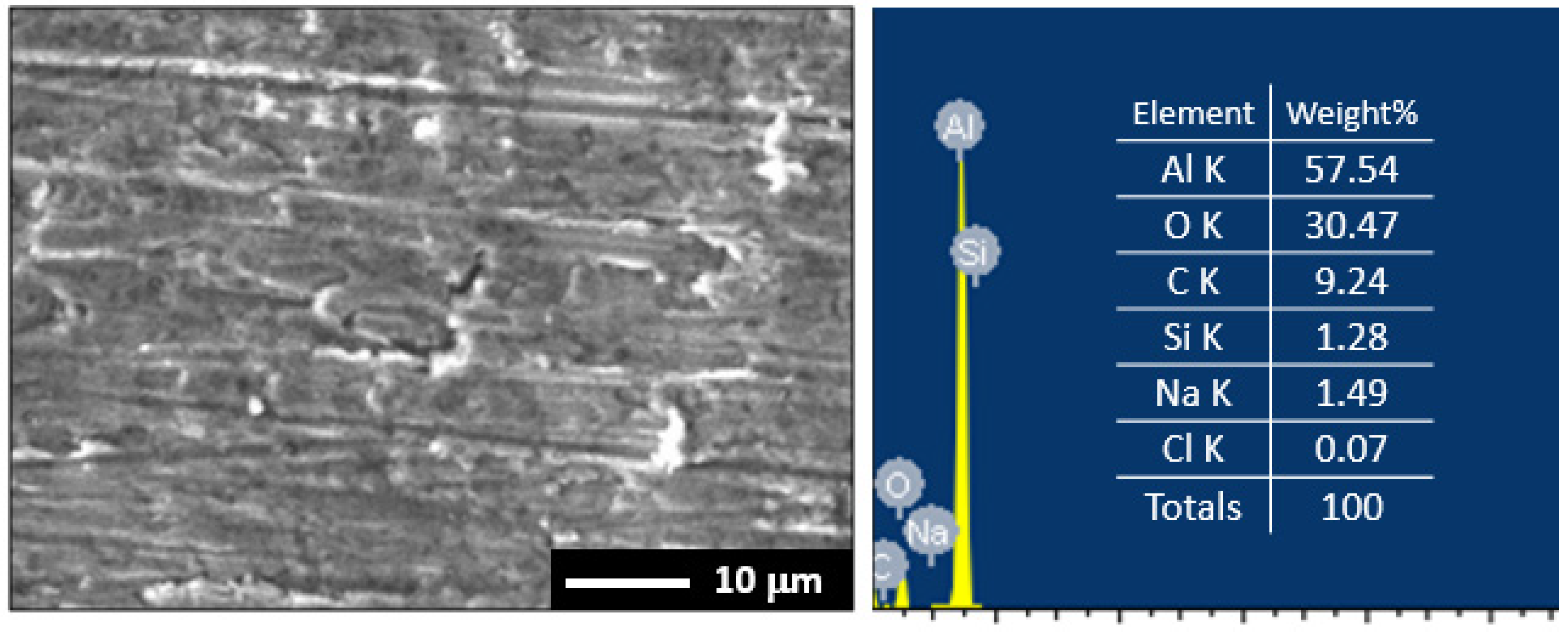
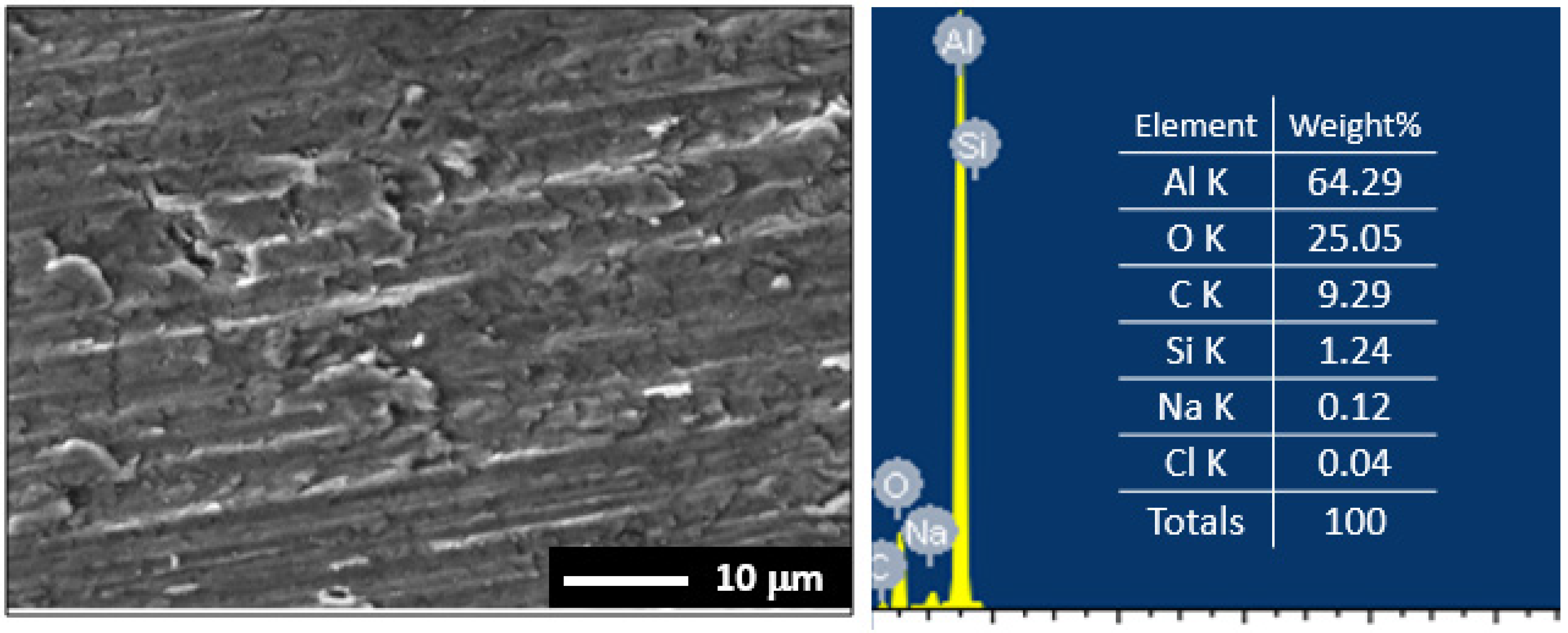
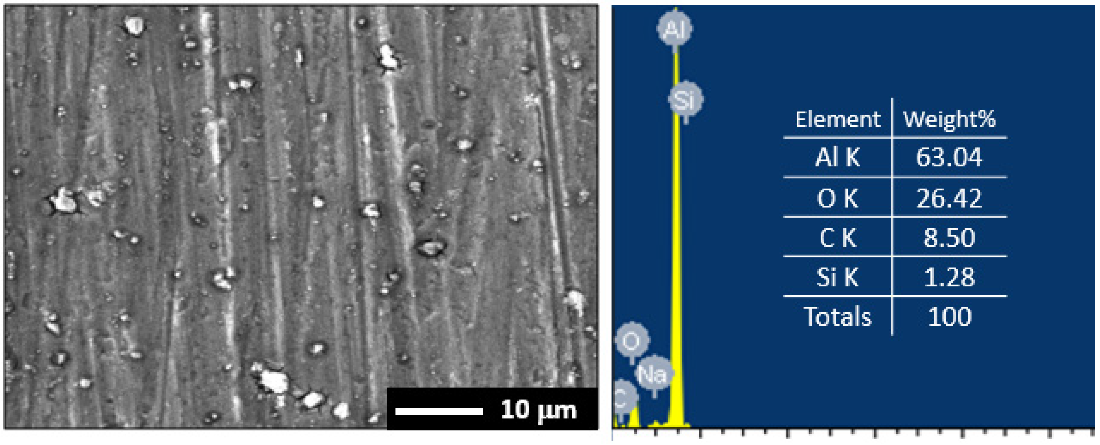
3.5. Surface Examinations

The SEM micrograph and EDX profile for the surface of the first Al-SiC nanocomposite after its exposure to 3.5% NaCl solutions for 48 h before applying −500 mV (Ag/AgCl) for 40 min are shown in Figure 13. The SEM images and the EDX profiles were also taken for the surface of the second and the third nanocomposites at the same conditions as shown in Figure 14; Figure 15, respectively. It is obvious from the SEM image of Figure 13 that the surface has a corrosion product layer and many pits. The corrosion product is an oxide film that was formed as per Reaction 7 and Reaction 8. This was confirmed by the elements detected on the surface via EDX spectrum. The weight percentage of the elements were as follows: 57.54% Al, 30.47% O, 9.24% C, 1.28% Si, 1.49% Na, and 0.07% Cl. The high percentages of Al and O suggest that the formed compound on the surface is the aluminum oxide, Al2O3.
The SEM image of the second nanocomposite, Figure 14, show the surface covered with a thick corrosion product and fewer pits compared to the surface of the first nanocomposite. The atomic percentages found on the surface via EDX of Figure 14 were as follows: 64.29% Al, 25.05% O, 9.29% C, 1.24% Si, 0.12% Na, and 0.04% Cl. The high percentages of Al and O suggest that the formed compound on the surface is the aluminum oxide, Al2O3. The surface of the nanocomposite is thus covered with Al2O3 film through which some pits were formed.
The surface of the third nanocomposite, Figure 15, shows a more compact corrosion product layer that is having very few pits compared to the surfaces of the first nanocomposite and the second nanocomposite. The atomic percentages found on the surface via EDX (Figure 15) were as the follows: 63.04% Al, 26.42% O, 8.50% C, 1.28% Si, and 0.76% Na. The highest percentages for the elements found on the surface were also for Al and O, which also confirms the formation of Al2O3. The prolonging of the milling time for the third nanocomposite thus increases its corrosion resistance and even the corrosion product layer if formed is more compact. The SEM/EDX analyses collectively prove that the third nanocomposite has the best corrosion resistance followed by the second nanocomposite and the least was for the first nanocomposite.

4. Conclusions

Three Al-2wt.% SiC nanocomposites were fabricated and processed after different milling routes. The corrosion of these composites after 1 h, 24 h and 48 h exposure periods of time in 3.5% NaCl solution has been investigated. Various electrochemical and spectroscopic techniques namely, potentiodynamic polarization, EIS, chronoamperometric current-time, SEM and EDX investigations. It has been found that all the fabricated nanocomposites show high value of RP. All electrochemical data confirmed that the increase of ball milling time increases the corrosion resistance of the nanocomposite via decreasing both jCorr and RCorr and increasing both of RS and RP. This effect was found to remarkably increase with the increase of exposure time of the nanocomposites in the chloride solutions from 1 h to 24 h and longer time to 48 h. The SEM images and EDX spectra obtained for the surface of the nanocomposites after being corroded confirmed that the increase of ball milling time for the fabricated samples as well as extending the time of immersion minimize the uniform and pitting corrosion.

Author Contributions

Conceptualization, S.M.A., E.-S.M.S., H.S.A.; methodology, S.M.A., E.-S.M.S., H.S.A., M.L.; formal analysis, S.M.A., E.-S.M.S., H.S.A.; Funding, H.S.A.; writing—original draft preparation, E.-S.M.S.; writing—review and editing, S.M.A., E.-S.M.S. and H.S.A.; supervision, N.H.A., H.F.A.; project administration, N.H.A., H.F.A. All authors have read and agreed to the published version of the manuscript.

Funding

This work acknowledges the fund from the King Saud University, Deanship of Scientific Research, College of Engineering Research Center.

Institutional Review Board Statement

Not applicable.

Informed Consent Statement

Not applicable.

Data Availability Statement

The data presented in this study are available within the manuscript.

Acknowledgments

The authors would like to extend their sincere appreciation to the King Saud University, Deanship of Scientific Research, College of Engineering Research Center for Funding. The first author also extends appreciation to RDO-MOE Postdoctoral Fellowship Program (PFP).

Conflicts of Interest

The authors declare no conflict of interest.

References

  1. Miracle, D. Metal matrix composites—From science to technological significance. Compos. Sci. Technol. 2005, 65, 2526–2540. [Google Scholar] [CrossRef]
  2. Sahin, Y.; Acilar, M. Production and properties of SiCp-reinforced aluminium alloy composites. Compos. Part A 2003, 34, 709–718. [Google Scholar] [CrossRef]
  3. Hassan, A.M.; Mayyas, A.T.; Alrashdan, A.; Hayajneh, M.T. Wear behavior of Al–Cu and Al–Cu/SiC components produced by powder metallurgy. J. Mater. Sci. 2008, 43, 5368–5375. [Google Scholar] [CrossRef]
  4. Miracle, D.B.; Donaldson, S.L. ASM Handbook. Composites; ASM International: Cleveland, OH, USA, 2001; Volume 21. [Google Scholar]
  5. Paciej, R.C.; Agarwala, V.S. Metallurgical variables influencing the corrosion susceptibility of a powder metallurgy aluminum/SiCw composite. Corrosion 1986, 42, 718–729. [Google Scholar] [CrossRef]
  6. ASM Handbook. Corrosion, 4th ed.; ASM International: Cleveland, OH, USA, 1992; Volume 13.
  7. Abdo, H.S.; Abdus Samad, U.; Mohammed, J.A.; Ragab, S.A.; Seikh, A.H. Mitigating Corrosion Effects of Ti-48Al-2Cr-2Nb Alloy Fabricated via Electron Beam Melting (EBM) Technique by Regulating the Immersion Conditions. Crystals 2021, 11, 889. [Google Scholar] [CrossRef]
  8. Abdo, H.S.; Seikh, A.H.; Fouly, A.; Ragab, S.A. Synergistic Strengthening Effect of Reinforcing Spark Plasma Sintered Al-Zn-TiC Nanocomposites with TiC Nanoparticles. Crystals 2021, 11, 842. [Google Scholar] [CrossRef]
  9. Seah, K.; Krishna, M.; Vijayalakshmi, V.; Uchil, J. Effects of temperature and reinforcement content on corrosion characteristics of LM13/albite composites. Corros. Sci. 2002, 44, 761–772. [Google Scholar] [CrossRef]
  10. Shimizu, Y.; Nishimura, T.; Matsushima, I. Corrosion resistance of Al-based metal matrix composites. Mater. Sci. Eng. A 1995, 198, 113–118. [Google Scholar] [CrossRef]
  11. El-Mahallawi, I.; Eigenfeld, K.; Kouta, F.H.; Hussein, A.; Mahmoud, T.S.; Ragaie, R.M.; Shash, A.Y.; Abou-Al-Hassan, W. Synthesis and Characterization of New Cast A356(Al2O3)P Metal Matrix Nano-Composites. In Proceedings of the 2nd Multifunctional Nanocomposites & Nanomaterials: International Conference & Exhibition, Sharm El Sheikh, Egypt, 11–13 January 2008. [Google Scholar] [CrossRef]
  12. Durai, T.G.; Das, K.; Das, S. Effect of mechanical milling on the corrosion behavior of Al–Zn/Al2O3 composite in NaCl solution. J. Mater. Sci. 2007, 42, 8209–8214. [Google Scholar] [CrossRef]
  13. Liu, Z.; Huang, B.; Gu, M. Corrosion behavior of Al/AlNp composite in alkaline solution. Mater. Lett. 2006, 60, 2024–2028. [Google Scholar] [CrossRef]
  14. de Salazar, J.G.; Ureña, A.; Manzanedo, S.; Barrena, M. Corrosion behaviour of AA6061 and AA7005 reinforced with Al2O3 particles in aerated 3.5% chloride solutions: Potentiodynamic measurements and microstructure evaluation. Corros. Sci. 1998, 41, 529–545. [Google Scholar] [CrossRef]
  15. Kiourtsidis, G.; Skolianos, S.M. Corrosion behavior of squeeze-cast silicon carbide-2024 composites in aerated 3.5 wt.% sodium chloride. Mater. Sci. Eng. A 1998, 248, 165–172. [Google Scholar] [CrossRef]
  16. Kiourtsidis, G.; Skolianos, S.M. Pitting corrosion of artificially aged T6 AA2024/SiCp composites in 3.5 wt.% NaCl aqueous solution. Corros. Sci. 2007, 49, 2711–2725. [Google Scholar] [CrossRef]
  17. Abdo, H.; Seikh, A.; Mohammed, J.; Soliman, M. Alloying Elements Effects on Electrical Conductivity and Mechanical Properties of Newly Fabricated Al Based Alloys Produced by Conventional Casting Process. Materials 2021, 14, 3971. [Google Scholar] [CrossRef]
  18. Trzaskoma, P.P. Pit Morphology of Aluminum Alloy and Silicon Carbide/Aluminum Alloy Metal Matrix Composites. Corrosion 1990, 46, 402–409. [Google Scholar] [CrossRef]
  19. Zakaria, H. Microstructural and corrosion behavior of Al/SiC metal matrix composites. Ain Shams Eng. J. 2014, 5, 831–838. [Google Scholar] [CrossRef]
  20. Almotairy, S.M.; Alharthi, N.H.; Alharbi, H.F.; Abdo, H. Superior Mechanical Performance of Inductively Sintered Al/SiC Nanocomposites Processed by Novel Milling Route. Sci. Rep. 2020, 10, 10368. [Google Scholar] [CrossRef] [PubMed]
  21. Khalil, K.A.; Sherif, E.-S.M.; Nabawy, A.M.; Abdo, H.S.; Marzouk, W.W.; Alharbi, H.F. Titanium Carbide Nanofibers-Reinforced Aluminum Compacts, a New Strategy to Enhance Mechanical Properties. Materials 2016, 9, 399. [Google Scholar] [CrossRef] [PubMed]
  22. Sherif, E.-S.M. Effects of exposure time on the anodic dissolution of Monel-400 in aerated stagnant sodium chloride solutions. J. Solid State Electrochem. 2011, 16, 891–899. [Google Scholar] [CrossRef]
  23. Latief, F.; Sherif, E.-S.M.; Almajid, A.; Junaedi, H. Fabrication of exfoliated graphite nanoplatelets-reinforced aluminum composites and evaluating their mechanical properties and corrosion behavior. J. Anal. Appl. Pyrolysis 2011, 92, 485–492. [Google Scholar] [CrossRef]
  24. Alharthi, N.; Sherif, E.-S.M.; Abdo, H.S.; El Abedin, S.Z. Effect of Nickel Content on the Corrosion Resistance of Iron-Nickel Alloys in Concentrated Hydrochloric Acid Pickling Solutions. Adv. Mater. Sci. Eng. 2017, 2017, 1–8. [Google Scholar] [CrossRef] [Green Version]
  25. Sherif, E.-S.M.; Ragab, S.A.; Abdo, H.S. Role of Vanadium Additions on the Corrosion Mitigation of Ti-6Al-xV Alloy in Simulated Body Fluid. Metals 2020, 10, 903. [Google Scholar] [CrossRef]
  26. Abdo, H.S.; Sherif, E.-S.M.; El-Serehy, H.A. Manufacturing of Ti-6%Al and Ti-6%Al-4%V Alloys and Their Corrosion in Sodium Chloride Solutions. Crystals 2020, 10, 181. [Google Scholar] [CrossRef] [Green Version]
  27. Sherif, E.-S.M.; Potgieter, J.; Comins, J.; Cornish, L.; Olubambi, P.; Machio, C. The beneficial effect of ruthenium additions on the passivation of duplex stainless steel corrosion in sodium chloride solutions. Corros. Sci. 2009, 51, 1364–1371. [Google Scholar] [CrossRef]
  28. Badawy, W.; Al-Kharafi, F.; El-Azab, A. Electrochemical behaviour and corrosion inhibition of Al, Al-6061 and Al–Cu in neutral aqueous solutions. Corros. Sci. 1999, 41, 709–727. [Google Scholar] [CrossRef]
  29. Sherif, E.-S.M.; Park, S.-M. Effects of 1,4-naphthoquinone on aluminum corrosion in 0.50 M sodium chloride solutions. Electrochim. Acta 2006, 51, 1313–1321. [Google Scholar] [CrossRef]
  30. Mazhar, A.; Badawy, W.; Abou-Romia, M. Impedance studies of corrosion resistance of aluminium in chloride media. Surf. Coat. Technol. 1986, 29, 335–345. [Google Scholar] [CrossRef]
  31. Tomcsányi, L.; Varga, K.; Bartik, I.; Horányi, H.; Maleczki, E. Electrochemical study of the pitting corrosion of aluminium and its alloys—II. Study of the interaction of chloride ions with a passive film on aluminium and initiation of pitting corrosion. Electrochim. Acta 1989, 34, 855–859. [Google Scholar] [CrossRef]
  32. Vera, M.L.; Linardi, E.; Lanzani, L.; Mendez, C.; Schvezov, C.E.; Ares, A.E. Corrosion resistance of titanium dioxide anodic coatings on Ti-6Al-4V. Mater. Corros. 2015, 66, 1140–1149. [Google Scholar] [CrossRef]
  33. Sherif, E.-S.M.; Abdo, H.S.; Alharthi, N.H. Beneficial Effects of Vanadium Additions on the Corrosion of Ti6AlxV Alloys in Chloride Solutions. Metals 2020, 10, 264. [Google Scholar] [CrossRef] [Green Version]
  34. Diamanti, M.V.; Bolzoni, F.M.; Ormellese, M.; Pérez-Rosales, E.A.; Pedeferri, M. Characterisation of titanium oxide films by potentiodynamic polarisation and electrochemical impedance spectroscopy. Corros. Eng. Sci. Technol. 2010, 45, 428–434. [Google Scholar] [CrossRef]
  35. Foley, R.T.; Nguyen, T.H. The Chemical Nature of Aluminum Corrosion: V. Energy Transfer in Aluminum Dissolution. J. Electrochem. Soc. 1982, 129, 464–467. [Google Scholar] [CrossRef]
  36. Hunkeler, F.; Frankel, G.S.; Bohni, H. Technical Note: On the Mechanism of Localized Corrosion. Corrosion 1987, 43, 189–191. [Google Scholar] [CrossRef]
  37. Sato, N. The stability of localized corrosion. Corros. Sci. 1995, 37, 1947–1967. [Google Scholar] [CrossRef]
  38. Natishan, P.M.; McCafferty, E.; Hubler, G.K. Surface Charge Considerations in the Pitting of Ion-Implanted Aluminum. J. Electrochem. Soc. 1988, 135, 321–327. [Google Scholar] [CrossRef]
  39. Sherif, E.-S.M.; Park, S.-M. Effects of 1,5-Naphthalenediol on Aluminum Corrosion as a Corrosion Inhibitor in 0.50 M NaCl. J. Electrochem. Soc. 2005, 152, B205–B211. [Google Scholar] [CrossRef] [Green Version]
Figure 1. SEM of the surface morphology for the milled nanocomposites using Route 3 at different magnifications, (a) 200 μm, and (b) 500 nm.
Crystals 11 01231 g001
Figure 2. XRD patterns collected for first Al-SiC (Route (1)), second Al-SiC (Route (2)), and third Al-SiC (Route (3)) bulk nanocomposites.
Crystals 11 01231 g002
Figure 3. Polarization curves for (1) fist Al-SiC nanocomposite, (2) second Al-SiC nanocomposite and (3) third Al-SiC nanocomposite after 1 h exposure in 3.5% NaCl.
Crystals 11 01231 g003
Figure 4. Polarization curves of (1) first Al-SiC nanocomposite, (2) second Al-SiC nanocomposite and (3) third Al-SiC nanocomposite after 24 h exposure in 3.5% NaCl.
Crystals 11 01231 g004
Figure 5. Polarization curves of (1) first Al-SiC nanocomposite, (2) second Al-SiC nanocomposite and (3) third Al-SiC nanocomposite after 48 h exposure in 3.5% NaCl.
Crystals 11 01231 g005
Figure 6. Nyquist plots obtained for (1) first Al-SiC nanocomposite, (2) second Al-SiC nanocomposite and (3) third Al-SiC nanocomposite after their immersion in 3.5% NaCl solutions for 1 h.
Crystals 11 01231 g006
Figure 7. Nyquist plots obtained for (1) first Al-SiC nanocomposite, (2) second Al-SiC nanocomposite and (3) third Al-SiC nanocomposite after their immersion in 3.5% NaCl solutions for 24 h.
Crystals 11 01231 g007
Figure 8. Nyquist plots obtained for (1) first Al-SiC nanocomposite, (2) second Al-SiC nanocomposite and (3) third Al-SiC nanocomposite after their immersion in 3.5% NaCl solutions for 48 h.
Crystals 11 01231 g008
Figure 9. Equivalent circuit model.
Crystals 11 01231 g009
Figure 10. PCT curves obtained at −500 mV for (1) first Al-SiC nanocomposite, (2) second Al-SiC nanocomposite and (3) third Al-SiC nanocomposite after their immersion in 3.5% NaCl solutions for 1 h.
Crystals 11 01231 g010
Figure 11. PCT curves obtained at −500 mV for (1) first Al-SiC nanocomposite, (2) second Al-SiC nanocomposite and (3) third Al-SiC nanocomposite after their immersion in 3.5% NaCl solutions for 24 h.
Crystals 11 01231 g011
Figure 12. PCT data obtained at −500 mV for (1) first Al-SiC nanocomposite, (2) second Al-SiC nanocomposite and (3) third Al-SiC nanocomposite after their immersion in 3.5% NaCl solutions for 48 h.
Crystals 11 01231 g012
Figure 13. SEM and EDX analyses collected for the first nanocomposite.
Crystals 11 01231 g013
Figure 14. SEM and EDX analyses collected for the second nanocomposite.
Crystals 11 01231 g014
Figure 15. SEM and EDX analyses collected for the third nanocomposite.
Crystals 11 01231 g015
Table 1. Milling modes.
Sample CodePhase 1Phase 2Phase 3
Speed (rpm)Time (h)Speed (rpm)Time (h)Speed (rpm)Time (h)
Route (1)15083004--
Route (2)150830041502
Route (3)150830044501
Table 2. Polarization data for the different nanocomposites in NaCl solution.
Nanocomposite/Timeβc/mV·dec−1ECorr/mVβa/mV·dec−1jCorr/µA·cm−2EPit/mVRP/Ω·cm2RCorr/mmpy
Nanocomposite 1 (1 h)85 ± 5−1168 ± 2130 ± 27.5 ± 0.2−700 ± 52980 ± 100.082 ± 0.003
Nanocomposite 2 (1 h)90 ± 5−1100 ± 3120 ± 54.2 ± 0.3−680 ± 55323 ± 120.046 ± 0.004
Nanocomposite 3 (1 h)95 ± 4−960 ± 5130 ± 31.3 ± 0.2−695 ± 518357 ± 100.014 ± 0.002
Nanocomposite 1 (24 h)93 ± 4−1118 ± 2123 ± 35.8 ± 0.2−665 ± 53970 ± 100.063 ± 0.002
Nanocomposite 2 (24 h)91 ± 4−970 ± 4125 ± 53.4 ± 0.1−620 ± 56734 ± 60.037 ± 0.003
Nanocomposite 3 (24 h)120 ± 5−875 ± 5110 ± 50.40 ± 0.1−680 ± 543478 ± 60.004 ± 0.003
Nanocomposite 1 (48 h)93 ± 7−1080 ± 5127 ± 33.7 ± 0.3−705 ± 56309 ± 110.041 ± 0.004
Nanocomposite 2 (48 h)93 ± 7−1065 ± 5128 ± 22.5 ± 0.2−680 ± 59368 ± 20.027 ± 0.005
Nanocomposite 3 (48 h)105 ± 5−1045 ± 5160 ± 52.1 ± 0.2−670 ± 513126 ± 20.023 ± 0.005
Table 3. Parameters obtained from fitting impedance data.
Nanocomposite/TimeImpedance Data
RS/Ω·cm2QRP1/Ω·cm2Cdl/F·cm2RP2/Ω·cm2
YQ/F·cm2n
Nanocomposite 1 (1 h)13.2 ± 0.30.0658 ± 0.0020.85 ± 0.05220 ± 50.0485 ± 0.0051632 ± 3
Nanocomposite 2 (1 h)15.8 ± 0.20.0574 ± 0.0010.87 ± 0.03389 ± 60.0299 ± 0.0064124 ± 6
Nanocomposite 3 (1 h)16.2 ± 0.50.0469 ± 0.0030.88 ± 0.04490 ± 60.0192 ± 0.0035221 ± 5
Nanocomposite 1 (24 h)14.5 ± 0.50.0587 ± 0.0030.86 ± 0.04314 ± 60.0367 ± 0.0033745 ± 5
Nanocomposite 2 (24 h)16.0 ± 0.60.0489 ± 0.0060.88 ± 0.02561 ± 40.0234 ± 0.0065987 ± 8
Nanocomposite 3 (24 h)16.8 ± 0.60.0396 ± 0.0060.89 ± 0.02643 ± 40.0145 ± 0.0066579 ± 8
Nanocomposite 1 (48 h)15.3 ± 0.70.0421 ± 0.0040.87 ± 0.03524 ± 60.0347 ± 0.0034589 ± 6
Nanocomposite 1 (48 h)16.4 ± 0.70.0355 ± 0.0040.89 ± 0.03712 ± 60.0265 ± 0.0035731 ± 6
Nanocomposite 3 (48 h)17.1 ± 0.90.0298 ± 0.0020.91 ± 0.05755 ± 50.0142 ± 0.0088951 ± 9
Publisher’s Note: MDPI stays neutral with regard to jurisdictional claims in published maps and institutional affiliations.

