Article

Timing Fluctuation Correction of A Femtosecond Regenerative Amplifier

1
State Key Laboratory of High Field Laser Physics and CAS Center for Excellence in Ultra-Intense Laser Science, Shanghai Institute of Optics and Fine Mechanics, Chinese Academy of Sciences, Shanghai 201800, China
2
XIOPM Research Center for Attosecond Science and Technology, State Key Laboratory of Transient Optics and Photonics, Xi’an Institute of Optics and Precision Mechanics, Chinese Academy of Sciences, Xi’an 710119, China
*
Authors to whom correspondence should be addressed.
Crystals 2021, 11(10), 1242; https://doi.org/10.3390/cryst11101242
Submission received: 2 September 2021 / Revised: 24 September 2021 / Accepted: 28 September 2021 / Published: 14 October 2021
(This article belongs to the Section Crystal Engineering)

Abstract

:
We report on the long-term correction of a timing fluctuation between the femtosecond regenerative amplifier and the reference oscillator for the seed 100 PW laser system in the Station of Extreme Light (SEL). The timing fluctuation was characterized by a noncollinear balanced optical cross-correlator that maps the time difference to the sum frequency intensity of the amplifier and oscillator laser pulses. A feedback loop was employed to correct the timing jitter by adjusting the time delay line in the amplifier beam path. The timing fluctuation was reduced to 1.26 fs root-mean-square from hundreds of fs over 10 hours. Benefitting from excellent performance and long-term stability, this timing jitter correction scheme, as a component of optical synchronization in the 100 PW laser facility, will be integrated into SEL.

1. Introduction

In the past few decades, the advent of the chirped pulse amplification (CPA) and optical parametric chirped pulse amplification (OPCPA) techniques has greatly promoted the development of super-intense ultrashort lasers [1,2]. So far, high-power femtosecond-level laser systems based on CPA and OPCPA techniques have achieved an output power of several petawatts (PW), even the 10 PW level [3,4,5,6,7,8,9,10]. In addition, there are several kilojoule-level high-energy laser facilities under construction that aim to achieve hundreds of petawatts of output and support a focus intensity of over 1023 W/cm2, such as the Station of Extreme Light (SEL), Extreme Light Infrastructure (ELI), Exawatt Center for Extreme Light Studies (XCELS), and Optical Parametric Amplifier Line (OPAL) [11,12,13,14]. Such extreme physical conditions have opened up many significant research fields, including laboratory astrophysics, particle acceleration, nuclear physics, and fast ignition [15,16,17,18]. In all of these laser facilities, the seed laser plays a key role for subsequent amplifier lines. For example, the seed pulses are split into several parts in OPCPA and optical parametric amplification (OPA) laser systems, which are used as the signal and pre-pump pulses, respectively [6,19,20]. The timing between seed and pump pulses significantly influences pulse stability and conversion efficiency and should be precisely controlled. František Batysta et al. demonstrated a compact scheme that synchronized the pump and signal pulses in an OPCPA to 17 fs RMS for hours [20]. Stephan Prinz et al. reported an active pump-seed-pulse synchronization for an OPCPA system and achieved 2 fs timing jitter between seed and pump pulses [21]. Moreover, the regenerative amplifier is indispensable to enhance pulse energy in the CPA system; the inherent principle of regenerative amplifiers implies the existence of pulse buildup time between input and output amplified pulses. Due to differences in regenerative amplifier architecture, the pulse buildup time ranges from hundreds of nanoseconds to a few microseconds, which corresponds to an optical path length of dozens to hundreds of meters. The timing jitter will be largely introduced by slight mechanical and pressure variations in the optical elements in the regenerative amplifier and temperature fluctuations, which negatively influence the output-time stability of the amplified pulse. In 2016, Alexis Casanova et al. reported the characterization and long-term correction of additive timing jitter between an oscillator and a regenerative amplifier [22].
In the Shanghai high repetition rate XFEL and extreme light (SHINE) facility project, the pulses of a 100 PW laser and X-ray free-electron laser (XFEL) will be simultaneously interacted at a target for pump-probe experiments in which the synchronization of colliding pulses is a key factor. As the pulse durations of the optical laser and XFEL are both less than 20 fs, the timing jitter between them needs to be controlled precisely. Therefore, the amplifiers of the 100 PW laser will be locked to an oscillator that is synchronized to the reference XFEL [23,24,25]. Moreover, CPA, OPA, and OPCPA techniques are applied in high-power laser systems. The synchronization between seed and pump pulses is important for the amplifiers. In this study, the timing jitter between the Ti:sapphire (Ti:Sa) oscillator and regenerative amplifier in a seed CPA laser system was measured by a noncollinear balanced optical cross-correlator (BOC) [22,26,27]. A home-built closed feedback loop was used to lock the timing jitter. By correcting the optical path length and optimizing the dispersion of the seed pulses, we finally decreased the timing fluctuation between the regenerative amplifier and oscillator pulses to 1.26 fs root-mean-square (RMS) over 10 h, which implies excellent long-term stability. This timing fluctuation correction system will be integrated into the pulse synchronization system of SEL.

2. Experimental Implementation

The seed laser of the 100 PW laser facility includes a CPA laser, OPA, and a gas-filled hollow-core fiber [19]. In the CPA laser system, a Ti:Sa oscillator delivered femtosecond (fs) pulses, which were split into two parts. One was sequentially stretched, amplified in a Ti:Sa regenerative amplifier, and compressed, which exported a pulse energy of ~7 mJ with a 35 fs pulse duration at the repetition rate of 1 kHz. The other part, with a pulse energy of ~2 nJ at the repetition rate of ~73 MHz, was used as the reference of the synchronization system in the laser facility.
The experimental setup is shown in Figure 1. The reference signal from the oscillator transmitted a multi-pass cavity (MPC) configuration to increase the beam optical path length. Subsequently, a chirped mirror pair (CMP) was employed for dispersion correction. On the other side, part of the pulses from the regenerative amplifier passed through a delay line that was controlled by a feedback circuit. As shown in the dashed box of Figure 1, the BOC was a noncollinear sum frequency generation (SFG) configuration, which provided background-free coincidence detection. Two pieces of type-I (θ = 29.2°, φ = 0°) BBO crystal with a thickness of 2 mm were used for SFG. A 100-μm-thick glass plate (GP) was inserted into one arm to introduce a time delay for the balanced detection operation. The sum frequency signals and their differential were measured by a balanced photodetector (Thorlabs PDB450). In the BOC measurement, for one arm, the sum frequency intensity was decided by the time difference between the two beams. Therefore, the relative timing fluctuation was reflected by the change in the sum frequency intensity recorded by the photodetector. Additionally, the initial intensity fluctuation of the beams was cancelled by the balance detection method. The analysis and control elements, including a PCIE data acquisition card and a feedback program, drove the delay line to correct the imbalance of the BOC. With this setting, the timing fluctuation was largely decreased by controlling the optical path of the amplifier beam. Limited by the response speed of the stepper motor (Sigma SGSP26), the feedback frequency was set to 5 Hz, which mainly corrected the low-frequency fluctuation in the amplified pulses.
The pulse buildup time in the regenerative amplifier was ~117 ns, which corresponded to a free space travel distance of ~35 m. To correct the optical path difference between the beams from the oscillator and the regenerative amplifier, an MPC configuration was introduced. In the MPC scheme, as shown in the light pink box in Figure 1, the focal lengths of two lens and two concave mirrors were 1 m and 250 mm, respectively, and the distance between the two concave mirrors was 810 mm. This design supported 50 round-trip transmissions of laser pulses with a total optical path length of ~40.5 m. By applying high reflectivity (>99%) concave mirrors, the MPC scheme achieved transmission efficiency of 65.7%. Afterwards, a CMP was used to correct the dispersion of the long-distance free space transmission. Through 22 round-trip reflections, the CMP provided a dispersion correction of −880 fs2. Moreover, to eliminate interference from the environment, the lens, MPC, and CMP were all placed in an enclosed box.

3. Results and Discussion

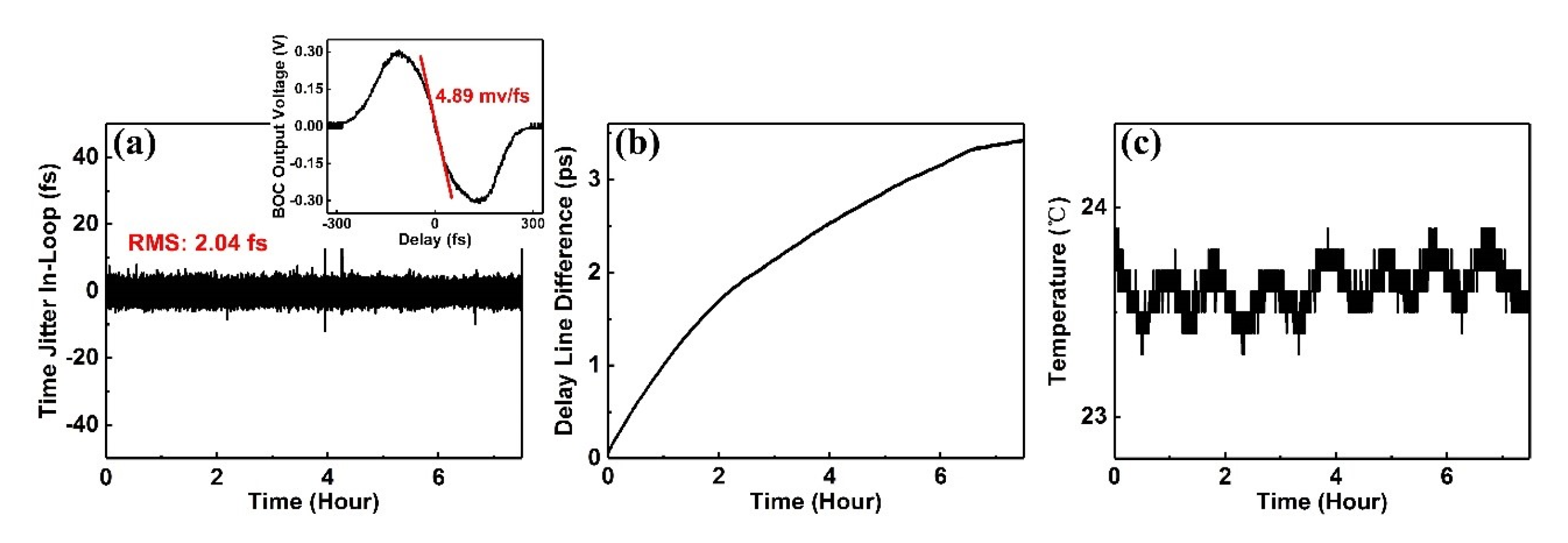
At first, we did not use the MPC scheme to correct the optical path difference and sent the beams from oscillator and regenerative amplifier directly to a BOC for timing jitter measurement. The BOC signal obviously changed in a few seconds, which indicated a fast timing fluctuation. By switching on the feedback loop, the fluctuation was significantly decreased. Figure 2a illustrates the long-term measurement results of the timing fluctuation correction under closed-loop conditions, and the corresponding S-shaped optical cross-correlation traces of the BOC (black curve) are shown in the insert. The fitting slope (red line) was 4.89 mv/fs, and the timing fluctuation was locked to 2.04 fs RMS for over 7 h, indicating the long-term performance stability of this synchronization scheme. However, as shown in Figure 2b, the delay line in the feedback loop increased monotonously during the measurement, representing a unidirectional timing drift of 3.4 picosecond (ps) over 7 h. Meanwhile, the long-term timing drift showed little correlation with environmental temperature fluctuations, which are shown in Figure 2c.
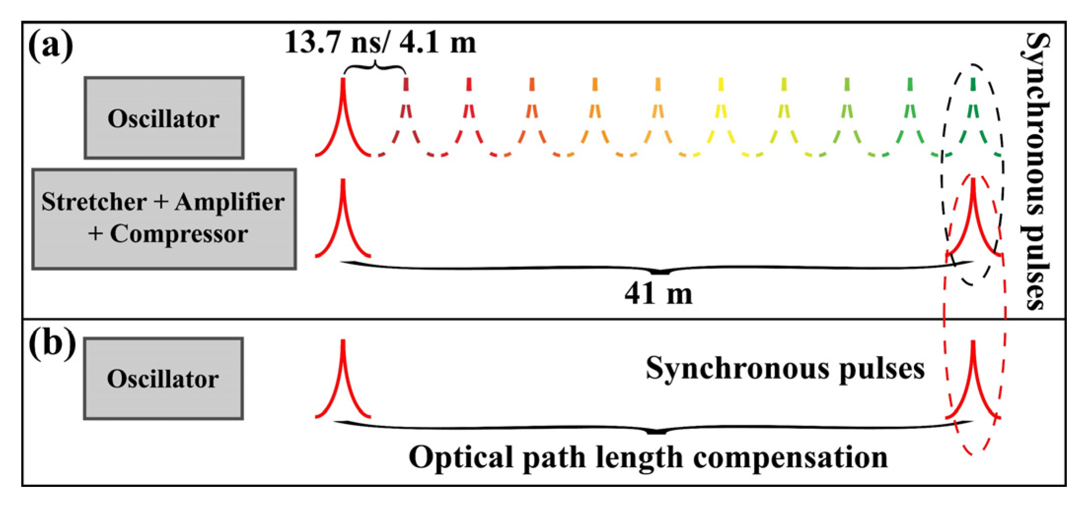
The external perturbations of the environment, such as temperature fluctuations, mechanical vibrations, and pressure variations, could influence the stability of the oscillator and the regenerative amplifier. However, in the above measurement, the timing shift was unidirectional and irrelevant to the fluctuation in environmental temperature. That means compared to the environment hazards, there was a very serious factor that caused a large and unidirectional timing drift between the oscillator and the amplifier. By measuring the arrival time of different oscillator pulses, we concluded that the timing shift was because of the change in length of the resonant cavity. A laser pulse transmitted ~41 m in the regenerative amplifier. Meanwhile, the same pulse traveled another 10 rounds in the oscillator (with ~73 MHz repetition rate). Therefore, without optical length correction, the sum frequency made in the BOC was between the amplified pulse and the oscillator pulse, which traveled another 10 rounds in the cavity, as shown in Figure 3a. Thus, the measured timing shift was significantly influenced by the change in cavity length. With the change in cavity length set to ∆L, the resulting timing shift was 10 × ∆L/c. A timing shift of 3.4 ps, shown in Figure 2b, could be caused by a ∆L of 102 μm. During a period of 7 h, changes of this magnitude were possible in the cavity.
After correction of the optical path length, a sum frequency was achieved between the regenerative amplified pulse and the oscillator pulse without further round trips in the cavity, as shown in Figure 3b. The synchronization was no longer influenced by the change in cavity length. The long-term timing jitter under the closed-loop condition, change in delay line, and temperature variation is shown in Figure 4. The timing jitter between oscillator and regenerative amplifier pulses was locked to 1.26 fs RMS for over 10 hours, as shown in Figure 4a. The insert in Figure 4a indicates S-shaped optical cross-correlation traces of BOC (black curve) and corresponding fitting slope (red line) with 7.5 mv/fs. Owing to the perfect dispersion correction by the CMP (for oscillator pulses) and the grating compressor (for regenerative amplifier pulses), the laser pulse durations of the two beams were both shorter than 100 fs, which ensured high intensity of the sum frequency and excellent sensitivity of the BOC. The long-term stable performance of this synchronization scheme was confirmed. The change in delay line (Figure 4b) and environmental temperature (Figure 4c) followed a similar trend, which implied that the timing jitter was actually affected by environmental temperature. The change in the delay line also indicated the timing fluctuation without the feedback loop, which showed a timing shift from −200 fs to 100 fs, as illustrated in Figure 4b. Therefore, the feedback loop decreased the timing fluctuation from hundreds of fs to 1.26 fs over 10 hours; in other words, the timing stability was improved by two orders of magnitude. In the scheme, the feedback frequency was limited by the delay stage, and timing jitter higher than 5 Hz could not be corrected by the current setup. Moreover, the timing accuracy was also limited by the BOC measurement, the accuracy of which was affected by the pulse duration. This was an effective design to correct the low frequency timing jitter of the amplifier within the laboratory environment, e.g., temperature fluctuation within ±0.5 °C and air flow-induced vibration lower than 5 Hz.

4. Conclusions

In summary, we demonstrated a synchronization scheme for the seed laser of the 100 PW laser facility in SEL. The timing fluctuation between the oscillator and regenerative amplifier pulses was reduced to 1.26 fs RMS over 10 hours. The timing jitter was measured by a noncollinear BOC and corrected by a feedback loop. To avoid influence from the oscillator cavity change, an MPC was employed to correct the optical path length difference between the oscillator and amplifier. A CMP configuration was used to correct the laser pulse dispersion introduced by long distance transmission and multiple reflections. By utilizing this system, precise long-term synchronization was achieved in the front end of the 100 PW laser facility. In the future, the system will be upgraded for the synchronization of the 100 PW laser and a reference oscillator, thus offering the possibility for high-power laser and XFEL pump-probe experiments.

Author Contributions

Conceptualization, K.L. and L.S.; methodology, K.L.; software, Y.L. (Yuxin Leng); validation, K.L., L.S. and X.W.; formal analysis, L.S.; investigation, H.L.; resources, Y.L. (Yanqi Liu); data curation, K.L.; writing—original draft preparation, K.L. and L.S.; writing—review and editing, L.S. and X.W.; funding acquisition, L.S. and Y.L. (Yanqi Liu) All authors have read and agreed to the published version of the manuscript.

Funding

This research was funded by the Shanghai high repetition rate XFEL and extreme light facility (SHINE) project; 100 Talents Program of CAS; Shanghai Pujiang Program (19PJ1410500).

Data Availability Statement

The data presented in this study are available on request from the corresponding author. The data are not publicly available due to the project regulations.

Conflicts of Interest

The authors declare no conflict of interest.

References

  1. Strickland, D.; Mourou, G. Compression of amplified chirped optical pulses. Opt. Commun. 1985, 56, 219–221. [Google Scholar] [CrossRef]
  2. Dubietis, A.; Jonušauskas, G.; Piskarskas, A. Powerful femtosecond pulse generation by chirped and stretched pulse parametric amplification in BBO crystal. Opt. Commun. 1992, 88, 437–440. [Google Scholar] [CrossRef]
  3. Aoyama, M.; Yamakawa, K.; Akahane, Y.; Ma, J.; Inoue, N.; Ueda, H.; Kiriyama, H. 085-PW, 33-fs Ti:sapphire laser. Opt. Lett. 2003, 28, 1594–1596. [Google Scholar] [CrossRef] [PubMed]
  4. Xu, L.; Yu, L.; Liang, X.; Chu, Y.; Hu, Z.; Ma, L.; Xu, Y.; Wang, C.; Lu, X.; Lu, H.; et al. High-energy noncollinear optical parametric–chirped pulse amplification in LBO at 800 nm. Opt. Lett. 2013, 38, 4837–4840. [Google Scholar] [CrossRef] [PubMed]
  5. Sung, J.H.; Lee, H.W.; Yoo, J.Y.; Yoon, J.W.; Lee, C.W.; Yang, J.M.; Son, Y.J.; Jang, Y.H.; Lee, S.K.; Nam, C.H. 42 PW, 20 fs Ti:sapphire laser at 01 Hz. Opt. Lett. 2017, 42, 2058–2061. [Google Scholar] [CrossRef]
  6. Zeng, X.; Zhou, K.; Zuo, Y.; Zhu, Q.; Su, J.; Wang, X.; Wang, X.; Huang, X.; Jiang, X.; Jiang, D.; et al. Multi-petawatt laser facility fully based on optical parametric chirped-pulse amplification. Opt. Lett. 2017, 42, 2014–2017. [Google Scholar] [CrossRef]
  7. le Garrec, B.; Papadopoulos, D.N.; le Blanc, C.; Zou, J.P.; Chériaux, G.; Georges, P.; Druon, F.; Martin, L.; Fréneaux, L.; Beluze, A.; et al. Design update and recent results of the Apollon 10 PW facility. Proc. SPIE 2017, 10238, 102380Q. [Google Scholar]
  8. Li, W.; Gan, Z.; Yu, L.; Wang, C.; Liu, Y.; Guo, Z.; Xu, L.; Xu, M.; Hang, Y.; Xu, Y.; et al. 339 J high-energy Ti:sapphire chirped-pulse amplifier for 10 PW laser facility. Opt. Lett. 2018, 43, 5681–5684. [Google Scholar] [CrossRef]
  9. Lureau, F.; Matras, G.; Chalus, O.; Derycke, C.; Morbieu, T.; Radier, C.; Casagrande, O.; Laux, S.; Ricaud, S.; Rey, G.; et al. High-energy hybrid femtosecond laser system demonstrating 2 × 10 PW capability. High Power Laser Sci. Eng. 2020, 8, 43. [Google Scholar] [CrossRef]
  10. Danson, C.N.; Haefner, C.; Bromage, J.; Butcher, T.; Chanteloup, J.C.-F.; Chowdhury, E.A.; Galvanauskas, A.; Gizzi, L.A.; Hein, J.; Hillier, D.I.; et al. Petawatt and exawatt class lasers worldwide. High Power Laser Sci. Eng. 2019, 7, 7. [Google Scholar] [CrossRef]
  11. Cartlidge, E. The light fantastic. Science 2018, 359, 382–385. [Google Scholar] [CrossRef]
  12. Zuegel, J.D.; Bahk, S.W.; Begishev, I.A.; Bromage, J.; Dorrer, C.; Okishev, A.V.; Oliver, J.B. Status of high-energy OPCPA at LLE and future prospects. In Proceedings of the 2014 Conference on Lasers and Electro-Optics (CLEO)—Laser Science to Photonic Applications, San Jose, CA, USA, 8–13 June 2014; pp. 1–2. [Google Scholar] [CrossRef]
  13. Shaykin, A.; Kostyukov, I.; Sergeev, A.; Khazanov, E. Prospects of PEARL 10 and XCELS Laser Facilities. Rev. Laser Eng. 2014, 42, 141. [Google Scholar] [CrossRef]
  14. Cartlidge, E. Eastern Europe’s laser centers will debut without a star. Science 2017, 355, 785. [Google Scholar] [CrossRef] [PubMed]
  15. Kodama, R.; Norreys, P.A.; Mima, K.; Dangor, A.E.; Evans, R.G.; Fujita, H.; Kitagawa, Y.; Krushelnick, K.; Miyakoshi, T.; Miyanaga, N.; et al. Fast heating of ultrahigh-density plasma as a step towards laser fusion ignition. Nat. Cell Biol. 2001, 412, 798–802. [Google Scholar] [CrossRef] [PubMed]
  16. Mourou, G.A.; Tajima, T.; Bulanov, S.V. Optics in the relativistic regime. Rev. Mod. Phys. 2006, 78, 309–371. [Google Scholar] [CrossRef] [Green Version]
  17. Fujioka, S.; Takabe, H.; Yamamoto, N.; Salzmann, D.; Wang, F.; Nishimura, H.; Li, Y.; Dong, Q.; Wang, S.; Zhang, Y.; et al. X-ray astronomy in the labora-tory with a miniature compact object produced by laser-driven implosion. Nat. Phys. 2009, 5, 821–825. [Google Scholar] [CrossRef] [Green Version]
  18. Daido, H.; Nishiuchi, M.; Pirozhkov, A. Review of laser-driven ion sources and their applications. Rep. Prog. Phys. 2012, 75, 056401. [Google Scholar] [CrossRef]
  19. Shao, B.; Li, Y.; Peng, Y.; Wang, P.; Qian, J.; Leng, Y.; Li, R. Broad-bandwidth high-temporal-contrast carri-er-envelope-phase-stabilized laser seed for 100 PW lasers. Opt. Lett. 2020, 45, 2215–2218. [Google Scholar] [CrossRef]
  20. Batysta, F.; Antipenkov, R.; Green, J.T.; Naylon, J.A.; Novák, J.; Mazanec, T.; Hříbek, P.; Zervos, C.; Bakule, P.; Rus, B. Pulse synchronization system for picosecond pulse-pumped OPCPA with femtosecond-level relative timing jitter. Opt. Express 2014, 22, 30281–30286. [Google Scholar] [CrossRef]
  21. Prinz, S.; Häfner, M.; Schultze, M.; Teisset, C.Y.; Bessing, R.; Michel, K.; Kienberger, R.; Metzger, T. Active pump-seed-pulse synchronization for OPCPA with sub-2-fs residual timing jitter. Opt. Express 2014, 22, 31050–31056. [Google Scholar] [CrossRef]
  22. Casanova, A.; D’Acremont, Q.; Santarelli, G.; Dilhaire, S.; Courjaud, A. Ultrafast amplifier additive timing jitter character-ization and control. Opt. Lett. 2016, 41, 898–900. [Google Scholar] [CrossRef] [PubMed]
  23. Xin, M.; Şafak, K.; Kärtner, F.X. Ultra-precise timing and synchronization for large-scale scientific instruments. Optica 2018, 5, 1564–1578. [Google Scholar] [CrossRef]
  24. Xin, M.; Şafak, K.; Peng, M.Y.; Callahan, P.T.; Kärtner, F.X. One-femtosecond, long-term stable remote laser synchronization over a 35-km fiber link. Opt. Express 2014, 22, 14904–14912. [Google Scholar] [CrossRef] [PubMed] [Green Version]
  25. Şafak, K.; Xin, M.; Callahan, P.T.; Peng, M.Y.; Kartner, F.X. All fiber-coupled, long-term stable timing distribution for free-electron lasers with few-femtosecond jitter. Struct. Dyn. 2015, 2, 041715. [Google Scholar] [CrossRef]
  26. Kim, J.; Chen, J.; Cox, J.; Kärtner, F.X. Attosecond-resolution timing jitter characterization of free-running mode-locked lasers. Opt. Lett. 2007, 32, 3519–3521. [Google Scholar] [CrossRef]
  27. Kärtner, F.; Wong, F.; Kim, J. Compact Background-Free Balanced Cross-Correlators. U.S. Patent 7,940,390 B2, 10 May 2011. [Google Scholar]
Figure 1. Experimental setup of synchronization system for the oscillator and regenerative amplifier. CMP, chirped mirror pair; PS, pointing stabilizer; BOC, balanced optical cross-correlator; BS, beam splitter; GP, glass plate; BBO, β-BaB2O4; BD, balanced photodetector.
Crystals 11 01242 g001
Figure 2. Timing fluctuation correction without optical path length correction: (a) timing jitter between the oscillator and the regenerative amplifier with the feedback loop closed (the insert shows optical cross-correlation traces); (b) variation of the delay line in the feedback loop; (c) temperature fluctuations in the environment.
Crystals 11 01242 g002
Figure 3. Synchronous pulses (a) without and (b) with optical path correction (curves in different colors represent different laser pulses).
Crystals 11 01242 g003
Figure 4. Timing fluctuation correction with optical path length correction: (a) timing jitter between oscillator and regenerative amplifier pulses (insert shows the “S” curve of the BOC measurement); (b) change in the delay line, (c) environment temperature fluctuation.
Crystals 11 01242 g004
Publisher’s Note: MDPI stays neutral with regard to jurisdictional claims in published maps and institutional affiliations.