Article

Porosity Distribution Simulation and Impure Inclusion Analysis of Porous Crystal Layer Formed via Polythermal Process

Research and Development Center of Membrane Science and Technology, State Key Laboratory of Fine Chemicals, School of Chemical Engineering, Dalian University of Technology, Dalian 116024, China
*
Author to whom correspondence should be addressed.
Crystals 2021, 11(11), 1347; https://doi.org/10.3390/cryst11111347
Submission received: 14 September 2021 / Revised: 29 October 2021 / Accepted: 29 October 2021 / Published: 5 November 2021

Abstract

:
In this work, we investigated the porosity distribution and separation property of the porous crystal layer formed via the polythermal process. The proposed porosity distribution model, considering both the cooling profile and the crystal settling effect, provided simulative results that met the MRI analysis experimental results with suitable agreement. Significant porosity variation from the top to the bottom of the crystal layer ( ϕ from 0.75 to 0.55 under rapid cooling profile) was detected. Meanwhile, the vertical supersaturation degree gradient induced by the fluid fluctuation could impact nucleation and crystal growth kinetic along with crystal particle settling. The resulting crystal layer possessed various impurity inclusion conditions. Under a moderate cooling profile (0.4 K·min−1), the volume fraction of closed pores against overall pores decreased from 0.75 to 0.36. The proposed model and experimental analysis approach were demonstrated to be helpful for porosity distribution simulation and impure inclusion analysis of layer crystallization.

Graphical Abstract

1. Introduction

Layer crystallization is known to be the effective and important separation technique in water treatment, chemical engineering, food industry, seawater desalination and other fields [1,2,3,4,5,6,7,8,9]. Crystal layers of a multiple geometrical nature were obtained as hyperpure or special-featured product using various supersaturated degree-generating mechanisms. The crystal layer usually forms a complex porous framework in various crystallization devices. The investigation of the properties of the crystal layer structure and mass transfer in this framework drew the constant focus, the separation effect and efficiency of crystallization [10,11,12], the fluid separation and impurity inclusion in the crystal layer of the layer crystallization [13,14,15,16,17,18,19], etc. The crystal layer formed via the polythermal process (under different cooling profile) possessed various structural properties along the characteristic direction of the cooling surface. The classic nucleation theory (CNT) and crystal size distribution (CSD) can generally be predicted as a log-linear distribution with increasing size in the crystallizer, and the crystal layer growth rate and thermal process duration are very different [20,21].
Simultaneously, the theory and research technology development on the structure and transport process analysis of complex porous media have achieved significant progress in recent decades [22,23]. The developed model can simulate the thermal properties [24,25], permeability of porous media [26,27] and the seepage, percolation and imbibition in porous media [28,29]. The application of such research progress covered various chemical engineering research aspects, such as crystallization [3,30,31,32,33,34,35], drying [36,37,38,39], dropwise condensation [40], etc. An ideal model was also developed to simulate the formation of the cylindrical porous crystal layer in our previous work [4,15]. The primary research also indicated that the formed crystal layer with complex structure is influenced not only by the in situ crystal nucleation and growth but also the crystal particle settling. The porosity distribution (PD) of the formed crystal layer is determined by the competition between crystal particle settling and in situ crystal growth. In principle, if the settling process is ignorable (e.g., the high viscosity and low liquid crystal density difference system), in situ crystal nucleation and growth will lead to the approximately uniform PD along the axial direction (or vertical direction). Thus, different from conventional porous media analysis [41,42], the structural and transport properties of the porous crystal layer were strongly influenced by external temperature curves and supercooling degree distribution. There is no reported investigation of simulating porosity distribution by crystallization via polythermal process. In addition, crystal particle migration (usually gravitational settling) will influence the overall structural properties of the porous crystal layer that is formed, which should be emphasized in the developed model.
In our primary work, when investigating in situ crystal nucleation and growth dominated the crystal layer formation, the porosity distribution of the crystal layer on the axial direction was assumed to be uniform to simplify the model (e.g., the studied system is the high viscosity and low crystal liquid density difference one, phosphoric acid solution) [4,5,15]. The average flow transport property of the porous crystal layer was then simulated based on the evaluation of the porous crystal layer structure in agreement with the experimental results [43]. However, the interaction between the actual porosity distribution of the porous crystal layer and the polythermal operation condition is still unknown. It is obvious that the porous crystal layers formed via different polythermal process do not merely have various porosity distributions but also significantly different fluid transfer properties. The outstanding fluid transfer property benefits the separation strategy, and the classic sweating (melting) process can be omitted due to the control of inclusion in the closed pores of the crystal layer [44]. The obtained pure crystal can then be melted or dissolved by hyperpure water to prepare a relevant hyperpure solution for various industrial uses [7,45,46].
In this article, we propose a model based on porous media theory and CNT to analyze the structure and phase separation properties of the porous crystal layer by considering the various cooling profile and crystal settling effects. The porous crystal layer formed in the cylindrical crystallizer was investigated in situ by specific crystallization devices combined with a magnetic resonance imaging (MRI) analysis system. The inclusion concentration in the closed pores of the porous crystal layer was analyzed to reveal the relationship between the modified porous structure and the impurity inclusion. With the developed model, the porosity distribution and separation properties of the porous crystal layer can be evaluated, which can be further applied to evaluate the pores’ distribution and separation effect of the porous crystal layer.

2. Theory

The principles of the model system are shown in Figure 1. The following assumptions are essential to simplify the model development:
(1) The crystal layer is formed by crystal growth and settling of suspended crystal particles. The crystals fall along the vertical direction of the crystallization system and the uncrystallized fluid (melt or solution) rises.
(2) There is no back-mixing during the settling of crystals. It is justified because the flow velocity of fluid is so slow, which is considered to be one-way and laminar flow. The effect of slight back-mixing and local circulation is neglected.
(3) The phase interface between the crystals and fluid (melt or solution) is in a quasi-steady-state, and the flow condition is laminar flow. The control step for crystal growth is the diffusion process. As the crystal growth rate is much slower than changes in the velocity, concentration, or temperature fields, the quasi-steady phase interface between the crystals and fluid is assumed, which has been used in previous study [14].
(4) The initial nucleation size distribution is assumed to follow a Gaussian distribution.
The primary nucleation rate in number basis can be described by the following approximate equation as a function of critical supercooling degree [47,48]:
J = k J Δ T lim m
where m and kJ are the nucleation order and is the nucleation constant, respectively. J is determined by the corresponding critical supersaturated degree, which is also related to the metastable zone width and the cooling rate.
Nyvlt’s equation expresses when the supercooling reaches the critical supercooling degree Δ T lim :
ln Δ T lim = 1 m m ln d C e d T T + 1 m ln r k J
where Ce is the equilibrium solute concentration at temperature T, r is the cooling rate, and K s−1. Equation (2) essentially presents a similar linear relationship between ln ( Δ T lim ) and ln ( r ) . The corresponding critical supersaturation degree S lim can also be obtained with known Δ T lim and the solubility equation.
The crystal growth rate G of a specific slice is written as [49,50,51,52]:
G = k g exp Δ E g R T t C C e a = k g exp Δ E g R T t S 1 C e a
where a and k g are the crystal growth order and growth constant, respectively, Δ E g is crystal growth activation energy, kJ mol−1. k g and Δ E g should be obtained by fitting the preliminary experimental data. The system temperature T ( t ) is determined by the polythermal conditions. T ( t ) = T 0 v t , as to the cooling crystallization process with the cooling rate of v, K s−1. The polythermal condition v has a significant influence on the nucleation and growth kinetic process, and, of course, the structural and transport properties of the formed porous crystal layer.
The primary nucleation is stochastic process, which is assumed to follow the Gaussian distribution [53]:
f = 1 σ 0 2 π exp l l 0 ¯ 2 2 σ 0 2
where l 0 ¯ and σ 0 are the mean characteristic size of the crystal and the variance of the distribution at time t = t0, respectively. The growth of each individual crystal is independent of the other crystals, and is governed by the same deterministic model. Thus, the mean characteristic size of the each individual crystals at t moment is:
l t ¯ = l 0 ¯ + 0 t G d t
As for the static slice, the secondary nucleation and agglomeration are ignorable; the population balance equation with one characteristic size l is described by [54]:
f l , t t + G l , Δ T f l , t l = 0
With the polythermal process, a porous crystal structure forms under the cooling rate r (K s−1). The actual driving force of the nucleation and crystal growth (supercooling degree Δ T = T T e ) is related to r and the fluid concentration at certain slice. Thus, when t = 0, the volume occupied by crystals VS in any infinite thin slice is expressed:
V S t = α l min l max N t = 0 f l l 3 d l
where α is the shape factor and N(t = 0) is the initial particle number.
Considering the crystal growth and synchronous settling process under an infinitesimal scale, the gravity settling of large crystals cannot be ignored. The gravity settling velocity u can be obtained with the classical gravity settling equations (seen in Supplementary Materials).
At slice n (the bottom slice), there are crystals that fall down from the upper slice (n − 1), if the gravity settling velocity u satisfies the following equation:
u d t d L
If u c r i d t = d L , there is a critical gravity settling velocity ucri and corresponding crystal size lcri. Thus, it should be noted that Equation (8) is a semi-empirical one and it is an ‘un-strict’ limit for the possible settling process. lcri and ucri are relevant to the research system.
A crystal with a size smaller than lcri is assumed to be unable to fall down to the next lower slice and, of course, the crystals falling from the upper slice will enter this slice. As for the bottom slice n, the volume occupied by the crystals at moment t is:
V S , n t = α l min , n l max , n N n t f n l l 3 d l + α l cri , n l max , n N n 1 t f n 1 l l 3 d l
For a certain slice i (1 < i < n) in the modelling system, the volume occupied by the crystals at t moment is:
V S , i t = α l min , i l cri , i N i t f i l l 3 d l + α l cri , i - 1 l max , i - 1 N i 1 t f i 1 l l 3 d l
In addition, the crystal number in the slice i at t moment can be deduced by the crystal number in the slice i at (t - dt) moment:
N i t = N i t d t l min , i l cri , i f i l d l + N i 1 t - d t l cri , i - 1 l max , i 1 f i 1 l d l
The porosity of certain slice i at t moment is:
φ i t = 1 V S , i t / A d L
where A is the sectional area of slice i.
With the increase in the number of crystals, the pore volume decreases and so does the porosity of each crystal slice. The maximum pore diameter of each slice i ( λ max , i ) also decreases. When λ max , i < l max , i the corresponding crystal settling will halt and the crystals whose size are greater than λ max , i will stay in the original slice.
According to the theoretical model proposed by Yu [27], λ max , i can be expressed by lmax as follows:
λ max , i = l max , i 2 φ i 1 φ i
It is clear that when ϕ i 1 3 , λ max , i l max , i is satisfied, and thus, Equations (10) and (11) should be modified to:
V S , i t = α l min , i l cri , i N i t f i l l 3 d l + l cri , i - 1 λ max , i - 1 N i 1 t f i 1 l l 3 d l + λ max , i l max , i N i t f i l l 3 d l
and
N i t = N i t d t l min , i l cri , i f i l d l + N i 1 t - d t l cri , i - 1 l max , i 1 N i 1 t f i 1 l l 3 d l + N i 1 t λ max , i l max , i N i t f i l l 3 d l
Thus, the porosity distribution (PD) of the porous crystal layer along the vertical direction can be obtained. It is clear that PD is a function of crystallization component (phase equilibrium parameters, crystal density, nucleation and growth parameter, etc.), polythermal condition (cooling rate, usually) and process duration.
The volume of the analyzing slice is constant and the fluid volume in the slice i at t moment is:
V L , i t = A d L V S , i t
With the assumption of no back mixing and one way flow, the flow rate ui on the interface of slice i-1 and i can be expressed as:
u i = d V L , i A φ i - 1 d t
Then, the Reynolds number at slice i can be expressed as:
Re i = d ¯ ρ u i μ
where d ¯ is the equivalent diameter of the porous channel in the slice i and μ is the viscosity of the fluid. With a known Re at a certain slice, the mass and heat transfer during the crystal layer formation can be evaluated, and the simulative deviation can be explained with classical nucleation and crystal growth theory.
With the one way flow, the mass balance of the slice i at t moment is expressed as:
d ρ L V L , i t d t + d ρ S V S , i ( t ) d t = 0
where ρ s is the density of the solid phase. As for the concentration of the liquid phase in the slice i at t moment, it is determined by the consumption of the crystal growth and the liquid exchange between the upper and lower slices, which is expressed as:
C i t = A φ i C i ( t d t ) d L + u i + 1 d t A φ i C i + 1 ( t d t ) u i d t A φ i 1 C i 1 ( t d t ) ρ S α l min , i l max , i N i t f i l l 3 d l A d L = φ i C i ( t d t ) + u i + 1 d t φ i C i + 1 ( t d t ) d L u i d t φ i 1 C i 1 ( t d t ) d L ρ S α l min , i l max , i N i t f i l l 3 d l A d L
Thus, with the known cooling rate and the temperature of the liquid phase at t moment, Ce can be calculated with the fitted solubility equation. The supersaturation degree in of the slice i at t moment Si(t) can be also obtained, which is substituted into Equation (3). The loop iteration should be carried out until the deviation is smaller than 0.0001, the simulation is moved to the next slice and the time is infinitesimal. With the set cooling profile and known crystallization metastable zone width, the simulative results were obtained and then compared with the experimental results obtained in the next section.

3. Experiment

3.1. Materials

Crystalline materials (urea crystals, analytical reagent grade, Tianjin Kewei Chemical Co., Ltd., Tianjin, China) were purified by recrystallization. Deionized water was manufactured by Dalian University of Technology and measured using a high-precision analytical balance (Mettler Toledo AB204-N, Greifensee, Switzerland) with an uncertainty of ±0.0001 g. Calcium phosphate (analytical reagent grade, Tianjin Kewei Chemical Co., Ltd., Tianjin, China), a commonly found impurity in the solution–crystallization separation process, was added as a marker agent. A trace amount of phosphate (a concentration equal to 5.0 mg/L) was added to avoid the possible impact on the solubility of the crystallization component. The ion concentrations in the crystal layer and inclusion fluid were measured by inductively coupled plasma optical emission spectrometry (ICP-OES) with the accuracy of ±0.001 mg/L.

3.2. Apparatus and Procedure

The experimental setup is shown in Figure 2. Two types of crystallizer were utilized.
The flat crystallizer (inner diameter 40 mm, height 25 mm) with a jacket around its wall (no jacket at the bottom side) was implemented to simulate the formation of the single crystal slice. The crystallization solution with known concentration was added and kept at the saturated temperature by the microcomputer controlled thermostatic bath with the precision of ± 0.1 K (CKDC, Nanjing FDL Co., Ltd., Nanjing, China). A pre-determined temperature profile was used in the experiments to acquire the demanded supercooling degree.
The crystal tower (inner diameter 20 mm, height 200 mm) with a valve at the bottom was implemented to simulate the formation of the whole porous crystal layer. This crystal tower was placed in the purpose-made thermostatic bath with the precision of ±0.1 K to obtain the required polythermal process. In the experiment on the redistribution of crystals along the vertical direction of the crystal tower, a high-definition camera was placed in front of the crystallizer; the images of the porous crystal layer formation were captured every 15 s until the cooing temperature reached the terminal value.
The crystal tower containing the porous crystal layer was placed directly in the magnetic resonance imaging (MRI) system (Suzhou NIUMAG Analytical Instrument Co., Ltd., Suzhou, China). The porosity on the settling cross section of the porous crystal layer was analyzed by the software embedded in the MRI system.
In the separation property experiment, a storage tank with a precision electronic balance (OHAUS Co., Limited, Shanghai, China), with a measuring range of 0 to 2200 g and uncertainty of ±0.01 g, was installed under the crystal tower to measure the mass of the discharged fluid. When we opened the valve and the inclusion fluid was discharged, the precision electronic balance was connected to a computer which could record the mass data. The volume of discharged fluid was then obtained with known fluid density.
The concentration of the calcium phosphate (which was added in the crystallization system in advance and had little impact on the urea crystallization) dissolved in the entrapped fluid was introduced to characterize the volume of the closed pore in the porous crystal layer. The volume fraction of the closed pore against the volume of the overall pores can be calculated by measuring the volume of discharged fluid and the concentration of calcium phosphate in the fluid. The terminal inclusion concentration of the crystal layer, which represented the separation effect of the crystal layer, was also measured by ICP-OES.

4. Results and Discussion

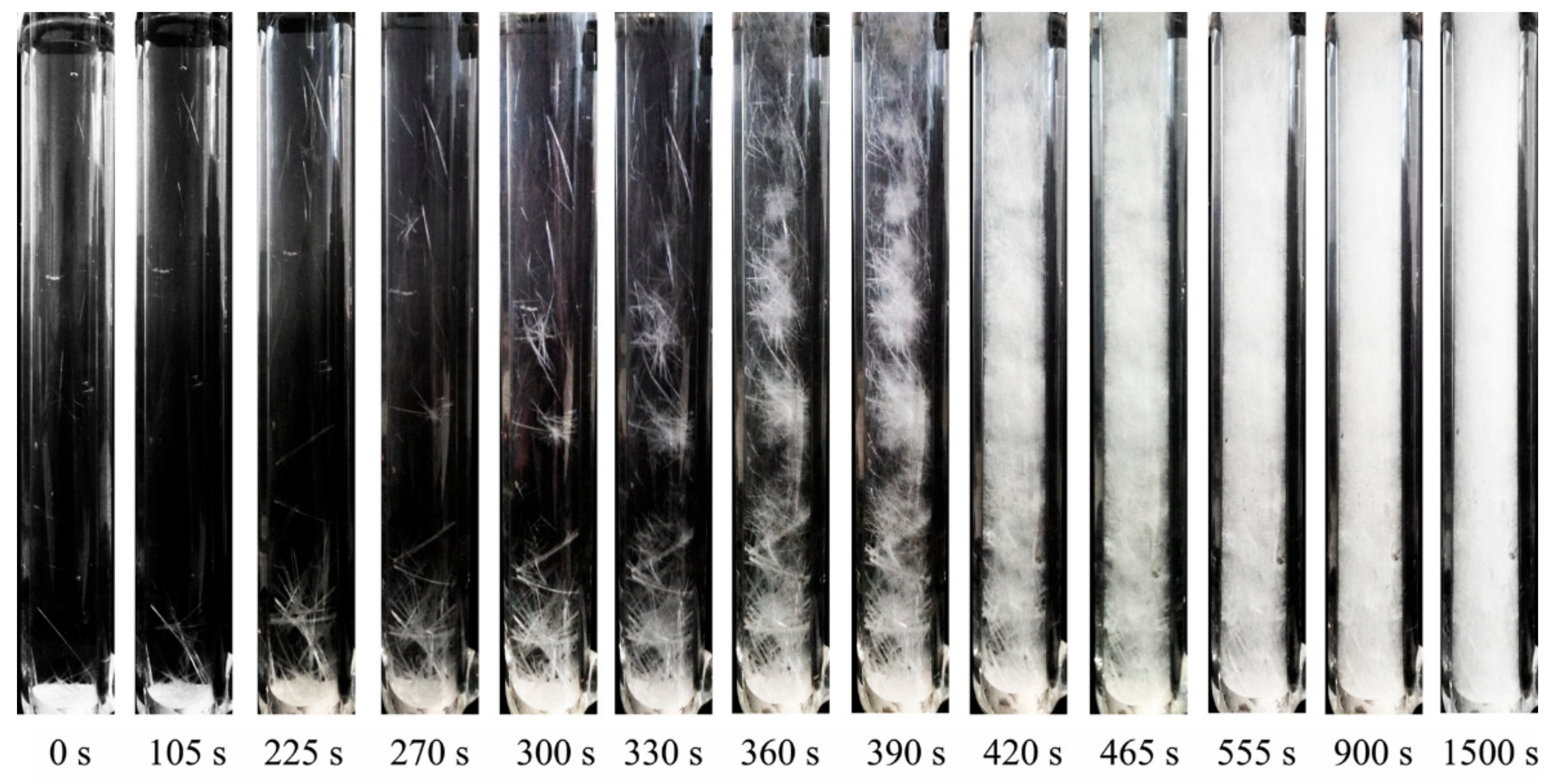
4.1. Formation Process of the Porous Crystal Layer

To reveal the actual formation process of the porous crystal layer, the captured images are shown in Figure 3. It should be noted that the nucleation and crystal growth process in the layer crystallization devices possess the feature of approximately self-similarity (considering the length of this article, the experiments setup, results and brief discussion are listed in Supplementary Materials), which indicated that the formation of the porous crystal layer was complicated. In addition to the stochastic crystal nucleus along the vertical direction of the crystal tower, a clear crystal settling process along the vertical direction was detected at the initial crystal layer formation. This gravity settling led to the redistribution of crystals (especially the large crystal particles), which also generated a rise in the supercooled or supersaturated fluid. Moreover, the crystals that finally formed the porous crystal layer at a certain height may not have shown in situ growth at the corresponding location, but descended from the upper slices (as shown in Figure 3). The supersaturated fluid rose to the upper location and led to the redistribution of the crystal nucleation and growth driving force. As a result, the crystal–fluid distribution along the vertical direction was determined by dynamic crystal layer formation and the crystal settling process rather than the thermodynamic phase equilibrium state of the crystallization system. This dynamic control effect was more significant when the density difference between the crystal phase and the fluid phase was large and the viscosity of the fluid was relatively small (which were both beneficial for settling). Thus, the resulting inconstant porosity along the vertical direction should be evaluated rather than considering the porous crystal layer as a symmetrical system. The model proposed in this article was based on ideal assumptions in the crystal tower by considering the two criteria of the crystal settling process. The simulative results were compared with the experimental result to reveal the feasibility and possible limitations of the two criteria.

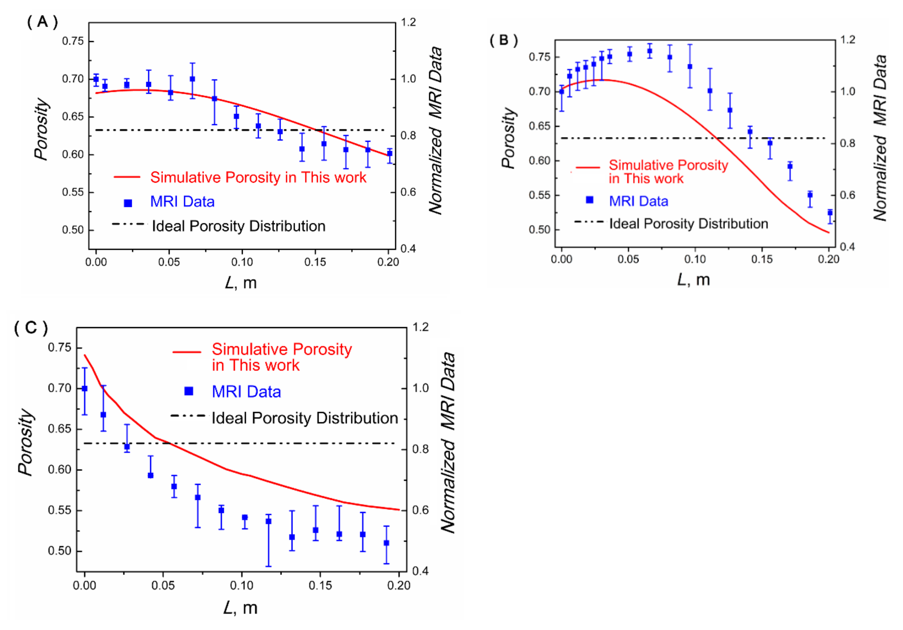
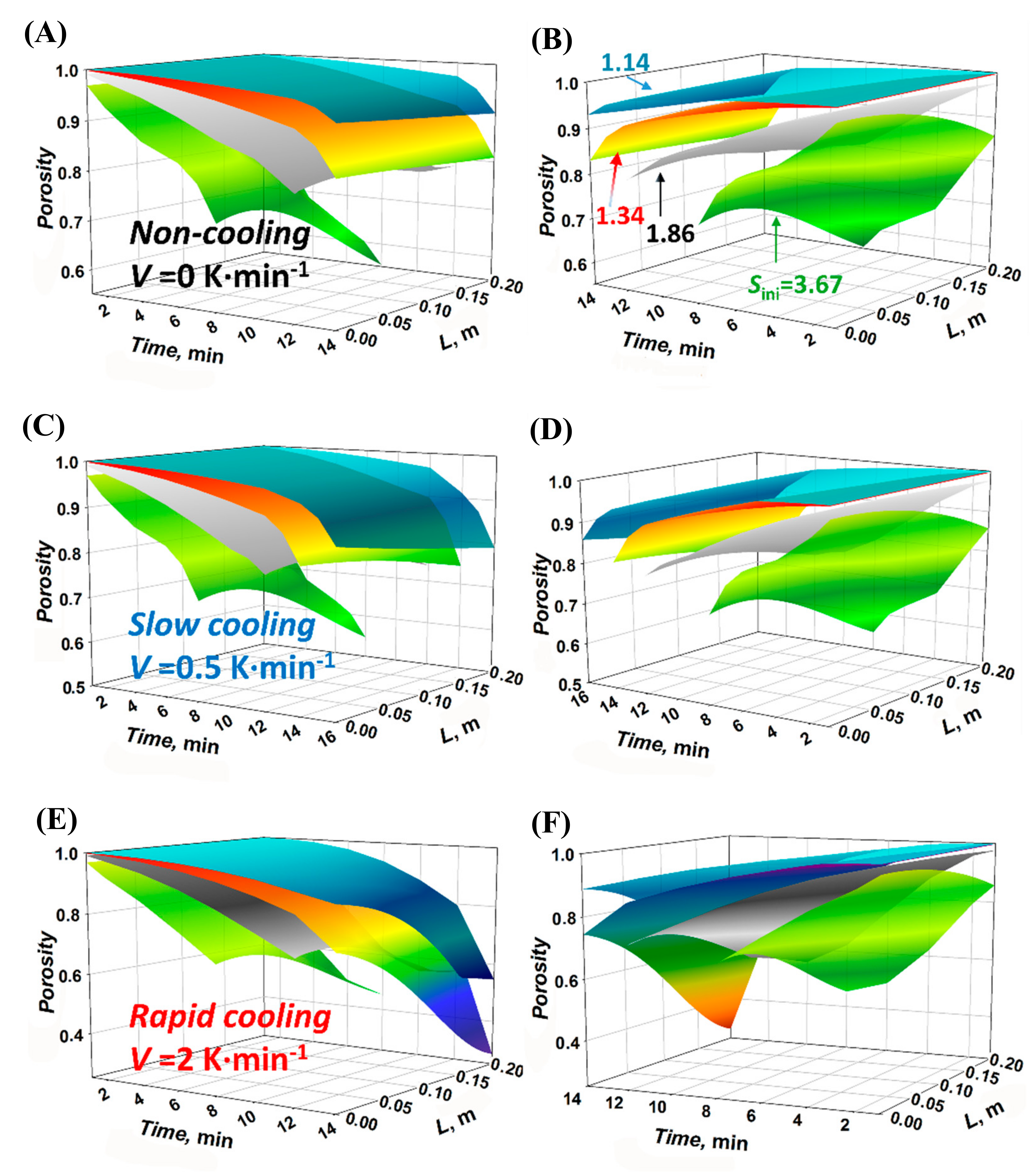
4.2. Porosity Distribution (PD) of the Crystal Layer

The model developed in this paper by considering the crystal settling and the simultaneous fluid transport can be helpful to reveal the PD of the formed crystal layer. The simulative results (obtained by Equations (4)–(12)) and experimental results (obtained by the MRI technology) under various operation conditions are shown in Figure 4 (the representative images of PD are shown in Supplementary Materials). Mean relaxation time of T2 spectrum (obtained from the software in the MRI system) was introduced as the characteristic value of the porosity and normalized by the mean relaxation time of the top porous slice T2,0. It should be noted that the actual porosity ϕ was the function of the T2. For the lack of the physical property parameters of the testing system, normalized MRI data T2 cannot be transferred to the porosity directly. Thus, we compared the simulated porosity with normalized MRI data. The simulative porosities with the proposed model in this paper showed suitable agreement with the measured MRI data along the axial direction, which indicated that the crystal particle settlement accompanied by crystal nucleation and growth did impact the establishment of the pores and channels in the crystal layer framework (the ideal porosity distribution that possesses the homogeneous pore structure along the possible settlement direction presented large deviations from the measured MRI data). Moreover, three obtained crystal layers were expected to have the similar total porosity with the same Te = 373 K and similar terminal temperature. Thus, the operation conditions ∆Tini and cooling rate v that influenced the crystallization kinetics (nucleation and growth rate) presented a significant impact on PD: under the high initial supercooling degree and non-cooling condition (Figure 4A), the simultaneous nucleation and rapid crystal growth from the top to the bottom of the crystallization system dominated the porous crystal layer formation process. The criterion which halted the crystal settling process was satisfied at the early stage of the procedure, which inhibited crystal settling and migration and then led to the smallest difference in the PD dispersion (approximately from 0.68 at the top slice to 0.58 at the bottom slice) among the three experiments. Under the small degree of supercooling and rapid cooling condition (Figure 4C), a wider PD (from 0.75 to 0.55) was obtained. The porosity diminished from the top to the bottom of the crystal layer framework along the gravity settling direction.
With the validation of the experimental results, further simulations were implemented to investigate the impact of changing crystal growth conditions (cooling rate v from 0 K·min−1 to 2 K·min−1, Sini from 1.14 to 3.67, which had covered most of the possible conditions in industrial applications) on the PD. The porosity transition under the testing space–time scales can be revealed with the set Sini, and the nucleation and crystal growth kinetic can be determined by Equations (1)–(3) (as shown in Figure 5). Essentially, the high cooling rate v and great Sini are both conducive to the quick nucleation and crystal growth, while, for the limitation of the mass and heat transfer, the Sini demonstrated a more profound effect on the heterogeneous porosity distribution than the cooling rate in the simulative range by providing a high mean supersaturated degree on the cooling interface.
Further investigation of how the crystal settling influences the crystal layer structure formation under the polythermal process should involve the simultaneous evaluation of the vertical supersaturation degree gradient induced by the fluid fluctuation, which determined the crystal growth rate. As shown in Figure 6, the crystal particle motion triggered the mass transfer of the supersaturated fluid (ascend phase) and the growing crystal (descend phase) between the simulative slices, which led to the diversified supersaturation degree S and significant supersaturation gradient.
The diversified S under various crystal growth conditions leads to the whole crystallization system reaching the equilibrium following the specific time and space sequence, which can be simulated and predicted by the proposed equations (Equations (1)–(6)). Simulative results are shown in Figure 6. With the increasing cooling rate, the diversity of the S distribution became increasingly significant, even if the initial S ranged from 1.14 to 3.67.
It should be noted that the asynchronous crystal growth rate could explain the formation of the possible complex (or undesired) structures not only in the single investigated hypothetical slice but also among the whole crystallization system. The supersaturation gradient that exceeded the equilibrium concentration induced the formation of a complex branched porous (B-P) structure. The B-P structure then aggravated the formation of the closed pores and the inclusion of the impurity phase.
The simulative results in Figure 5 and Figure 6 also emphasize that slight settling can result in an obviously differentiated S and porosity distribution, and so on. Accompanying the formation of this complex structure, the uneven heat transfer (release of the latent heat of crystallization) and mass transfer (diffusion on the concentration gradient) positively aggravate the establishment of the irregular geometry.
In addition, uneven crystal growth in the various simulated slice can lead to the diverse consumption rate of the supersaturated degree. Under the polythermal process, S in the corresponding slice could easily break the top limit of the critical supersaturated degree S lim (also mentioned as metastable zone width, MSZW). In the simulative aqueous solution, S lim , v = 0 K · min - 1 = 1.03 , S lim , v = 0.5 K · min - 1 = 1.16 , S lim , v = 1.0 K · min - 1 = 1.19 (the constants utilized were measured in our previous work [55] and provided in Supplementary Materials). The persistent nucleation and uneven crystal growth determined the differentiation of the structure. Fluid inclusion was aggravated simultaneously with the increasing complexity of the porous crystal layer. Overall transport and separation abilities of the porous media were then reduced.

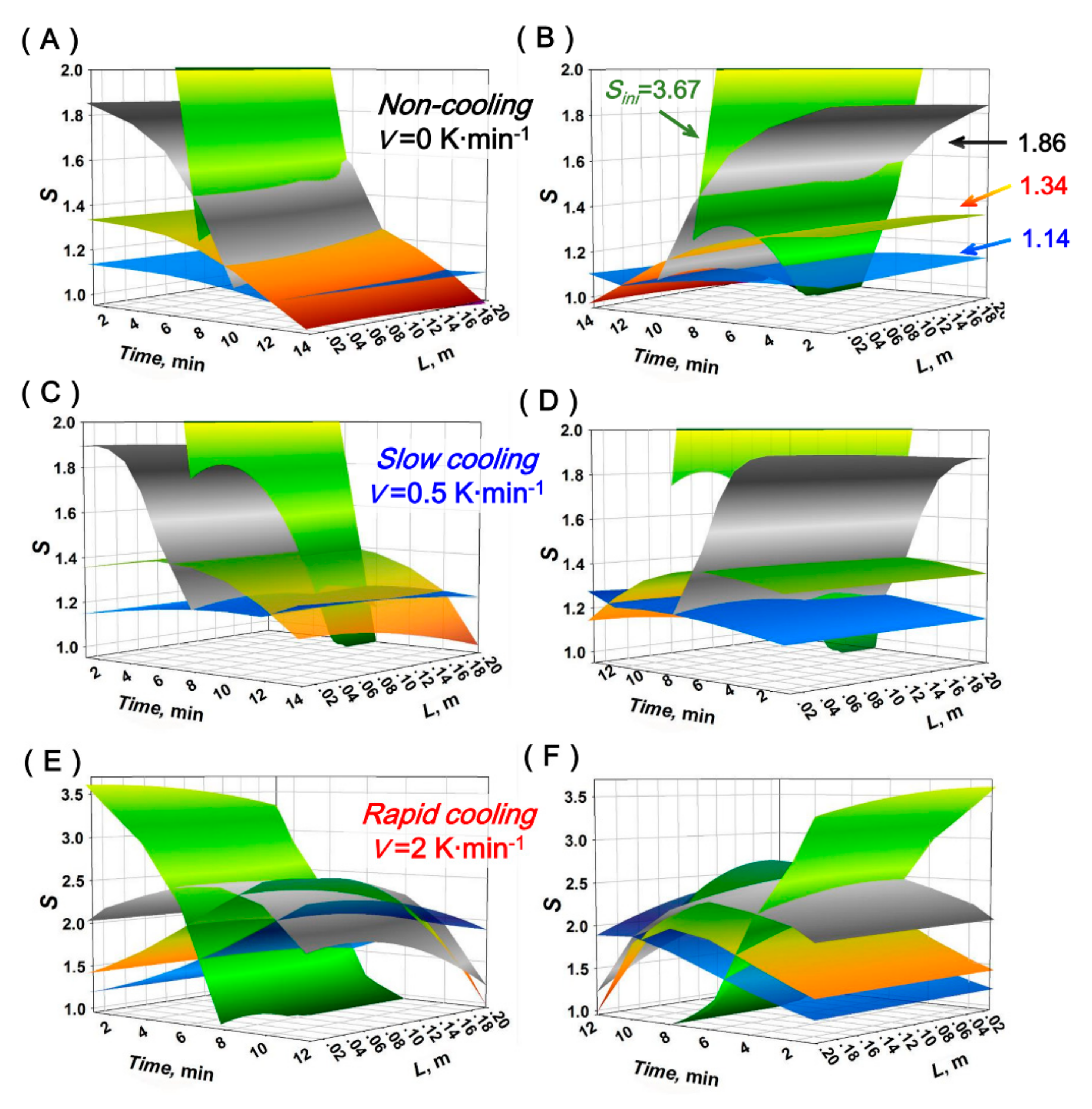
4.3. The Inclusion and the Separation Property Analysis

To illustrate the combined impact of the physical and crystallization kinetic properties of the crystal–fluid systems on the dynamic formation of the porous structure and the separation property, the nucleation and growth rate of two investigated systems (urea–H2O and KNO3–H2O, which have significantly different nucleation and crystal growth kinetics) under different polythermal procedures are simulated (shown in Figure 7). As mentioned above, crystal settling and the accompanying fluid fluctuation can be restrained to a certain extent if the fluid possesses a high viscosity and the density difference between the fluid and crystal phase is small. (The crystal nucleation and growth parameters of the two systems, k g , Δ E and a are listed in Supplementary Materials.) The instantaneous nucleation and growth rate are adopted at the initial stage of the porous framework establishment (the average porosities ϕ of the simulative system are approximately 0.84, the simulative volume is expanded to 2 m to test the forecasting ability of proposed mode under the industrial scale conditions). Due to the diverse density difference between the fluid and crystal phases and the special unsynchronized nucleation and growth, PD presents various results (obtained by the Equations (1)–(16), as shown in the first row figures of Figure 7). In addition, with the increasing cooling rate, the nucleation of KNO3 occupies a leading position step by step in the porous structure establishment process. The nucleation rate of the KNO3–H2O system even surpasses the nucleation rate of the urea–H2O system under the rapid cooling conditions (from left to right, second row of Figure 7) because the urea–H2O system possesses a higher crystal growth rate (linear velocity), which can consume the degree of supersaturation faster than the KNO3–H2O system. The KNO3–H2O system, which possesses a high degree of supersaturation, results in rapid, uncontrollable nucleation. This rapid, uncontrollable nucleation in the layer crystallization is generally known to be able to lead to the formation of closed pores in the crystal layer and the inclusion of the impure fluid. The undesired separation eventually occurs. Under a different growth rate (from left to right, third row of Figure 7), the crystals will grow to various sizes and aspect ratios. Large single particles that have a small ratio of length to diameter can establish a porous solid phase with lower structural complexity, which may enhance the transport properties and separation effect involved in the chemical engineering process.
Thus, as a further illustration of the formation of closed pores, impurity inclusion and corresponding separation influence calcium phosphate, a commonly found impurity in the solution–crystal separation process, which was added in the urea aqueous solution system as a marker agent. The introduction of this calibration agent was utilized to evaluate the concentration of the inclusion in the formed closed pores of the crystal layer (the fluid filling in the open pores was discharged during the seepage process).
The PD under three different polythermal procedures (0.2, 0.4 and 0.6 K min−1, which were commonly cooling rate in industrial crystallization) were simulated by the proposed model from Equations (17)–(20); the simulative results are shown in Figure 8. The overall porosities of the three simulated crystal layers were kept at 0.476 ± 0.005. With the moderate cooling rate of 0.4 K min−1, the minimum standard deviation of PD was obtained, 0.055. As a comparison, the standard deviations of PD of 0.2 K min−1 and 0.6 K min−1 were 0.076 and 0.078, respectively. The inclusion concentrations of calcium phosphate in the porous crystal layer after fluid seepage process (three sampling points from top to bottom) were measured. In addition, the volume fractions of closed pores (which will definitely entrap the impurity and lead to inclusion) and overall porous pores were obtained to illuminate the functional mechanism of nucleation and growth kinetic on the distribution of the pores and the formation of closed pores. The results revealed the further impact of the diverse structure properties and crystallization kinetics on the phase separation, which are also shown in Figure 8.
The lowest inclusion concentration (Cinclusion, mg/L) was obtained under the 0.4 K min−1 process. The experimental results indicated that the PD was optimized, and the formation of closed pore was inhibited. The experimental results demonstrate that this moderate cooling rate (0.4 K min−1) could avoid the exploding nucleation and uncontrollable growth compared to 0.6 K min−1; moreover, this cooling profile (0.4 K min−1) could provide enough driving force to maintain the crystal growth to inhibit the excessive crystal settling compared to 0.2 K min−1, which meant the criterion that halted the crystal settling process was satisfied at this condition. Moreover, the evaluation of the closed pores volume further confirmed that the under the different polythermal process (which led to different crystal nucleation and growth kinetic), the pore structures of the formed crystal layer possessed significant differences (shown in the right image of Figure 8). It can be seen that almost 80% of the volume of the overall pores at the bottom of the crystal layer were closed pores under the rapid cooling profile (0.6 K min−1). Under the moderate cooling profile (0.4 K min−1), with the halted the crystal settling and fluid migration, the volume fraction of closed pore against overall pores decreased by half (from 0.75 to 0.36). Thus, the porous crystal layer with the desired fluid transport performance, less inclusion and better separation properties was eventually established. The porous crystal layer obtained at the top section under the cooling rate of 0.4 K min−1 was a hyperpure crystal product. The impurity concentration was smaller than 0.05 mg L−1, which met the requirement for the electronic-grade chemicals. A desirable fluid–crystal phase separation was acquired in the porous crystal layer formed under the proper polythermal process. As the simplified model is a preliminary exploration, the well-simulated model considering complex fluid flow will be improved in our future work.

5. Conclusions

In this paper, a mathematical model (Equations (7)–(16)) to analyze the structure and separation properties of the porous crystal layer formed under a polythermal process was proposed and validated. The porosity distribution (PD) caused by the various polythermal processes (cooling processes in this article) and crystal settling effect was emphasized in this model. The particle motion and the mass transfer generated by crystal settling and consequent supersaturated fluid rising must be accounted for.
Simulative PD results were in accordance with the result of the experiments, which we carried out in a specially made crystallizer equipped with an MRI analysis system. A better understanding of this process can be helpful for the analysis of the high-porosity crystal layer with an irregular and complex structure deposited on an interface or in limited space, which are commonly found in layer crystallization, scaling on the membrane interface and other related crystallization separation processes.
For the separation process, the excessive deposition, fluid migration and porous framework construction have significant impacts on the heterogeneous distribution of the porosity and the formation of closed pores, which both determined the fluid–crystal phase separation effect of the porous crystal layer. Two crystallization systems (urea–H2O and KNO3–H2O, which had significant differences in the nucleation and growth kinetics) were introduced to reveal the impact of supersaturated fluid fluctuation on local nucleation and growth kinetics, which determined the formation of the closed pores, the fluid inclusions and the phase separation properties of the crystal layer. The various PD, inclusion concentration and distinct volume fractions of closed pores further confirmed that the various polythermal processes intensify the impacts by modifying the nucleation and growth kinetics and the crystal particle settling.
This research also confirmed that an accurate model (from Equations (7)–(20)) to simulate the crystallization process occurring under the various cooling profiles is critical for both porous media research and chemical engineering separation. To obtain the hyperpure crystal layer or solid product, an accurately designed polythermal profile plays a pivotal role in the process design and optimization of layer crystallization.

Supplementary Materials

The following are available online at https://www.mdpi.com/article/10.3390/cryst11111347/s1, Figure S1: Images of PD obtained by MRI system experiments, Figure S2: Images of PD obtained by MRI system experiments (2), Figure S3: Experimental apparatus for the imitative porous crystal slice, Figure S4: The images of the formation procedure for the porous crystal slice, Figure S5: The detailed image of the initial nucleus distribution and growth at the bottom of the crystal tower, Table S1: Crystallization relevant data of the investigated systems in this paper, Table S2: Solubility of Urea in Water, Table S3: Solubility of KNO3 in Water.

Author Contributions

Conceptualization and methodology, X.J.; experimental synthesis and characterization, Y.M.; theoretical simulation, Z.L.; writing—original draft, Y.M. and X.J.; writing—review and editing, X.L., W.X., G.H., X.W. and X.J.; All authors have read and agreed to the published version of the manuscript.

Funding

We acknowledge the financial contribution from Science Fund for Creative Research Groups of the National Natural Science Foundation of China (22021005), National Natural Science Foundation of China (grant no. 21978037), Fundamental Research Funds for the Central Universities (DUT19TD33), and National Key Research and Development Program of China (Grant No. 2019YFE0119200), Support Plan of Innovative Talents of Liaoning Province (XLYC1901005, XLYC1907149) and Dalian Innovative Science and Technology Fund (2020JJ26SN064).

Data Availability Statement

Data can be made available upon request from the corresponding author.

Conflicts of Interest

The authors declare no conflict of interest.

References

  1. Ulrich, J.; Jones, M.J. Industrial Crystallization. Chem. Eng. Res. Des. 2004, 82, 1567–1570. [Google Scholar] [CrossRef]
  2. Sha, Z.L.; Yin, Q.X.; Chen, J.X. Industrial Crystallization: Trends and Challenges. Chem. Eng. Technol. 2013, 36, 1286. [Google Scholar] [CrossRef]
  3. Jiang, X.B.; Hou, B.H.; He, G.H.; Wang, J.K. Falling film melt crystallization (I): Model development, experimental validation of crystal layer growth and impurity distribution process. Chem. Eng. Sci. 2012, 84, 120–133. [Google Scholar] [CrossRef]
  4. Jiang, X.; Hou, B.; He, G.; Wang, J. Falling film melt crystallization (II): Model to simulate the dynamic sweating using fractal porous media theory. Chem. Eng. Sci. 2013, 91, 111–121. [Google Scholar] [CrossRef]
  5. Jiang, X.; Xiao, W.; He, G. Falling film melt crystallization (III): Model development, separation effect compared to static melt crystallization and process optimization. Chem. Eng. Sci. 2014, 117, 198–209. [Google Scholar] [CrossRef]
  6. Gilbert, S.W. Melt Crystallization—Process Analysis and Optimization. AIChE J. 1991, 37, 1205–1218. [Google Scholar] [CrossRef]
  7. Yazdanpanah, N.; Myerson, A.; Trout, B. Mathematical Modeling of Layer Crystallization on a Cold Column with Recirculation. Ind. Eng. Chem. Res. 2016, 55, 5019–5029. [Google Scholar] [CrossRef]
  8. Kalista, B.; Shin, H.; Cho, J.; Jang, A. Current development and future prospect review of freeze desalination. Desalination 2018, 447, 167–181. [Google Scholar] [CrossRef]
  9. Ding, S.; Huang, X.; Yin, Q.; Dong, Y.; Bai, Y.; Wang, T.; Hao, H. Heat transfer and its effect on growth behaviors of crystal layers during static layer melt crystallization. Chem. Eng. Sci. 2021, 233, 116390. [Google Scholar] [CrossRef]
  10. Meng, S.; Hsu, Y.-C.; Ye, Y.; Chen, V. Submerged membrane distillation for inland desalination applications. Desalination 2015, 361, 72–80. [Google Scholar] [CrossRef]
  11. Ye, W.; Lin, J.; Tækker Madsen, H.; Gydesen Søgaard, E.; Hélix-Nielsen, C.; Luis, P.; Van der Bruggen, B. Enhanced performance of a biomimetic membrane for Na2CO3 crystallization in the scenario of CO2 capture. J. Membr. Sci. 2016, 498, 75–85. [Google Scholar] [CrossRef] [Green Version]
  12. Jia, S.; Jing, B.; Hong, W.; Gao, Z.; Gong, J.; Wang, J.; Rohani, S. Purification of 2,4-dinitrochlorobenzene using layer melt crystallization: Model and experiment. Sep. Purif. Technol. 2021, 270, 118806. [Google Scholar] [CrossRef]
  13. Chen, X.D.; Wu, W.D.; Chen, P. An analytical relationship of concentration-dependent interfacial solute distribution coefficient for aqueous layer freeze concentration. AIChE J. 2015, 61, 1334–1344. [Google Scholar] [CrossRef]
  14. Zhou, L.; Su, M.; Benyahia, B.; Singh, A.; Barton, P.I.; Trout, B.L.; Myerson, A.S.; Braatz, R.D. Mathematical modeling and design of layer crystallization in a concentric annulus with and without recirculation. AIChE J. 2013, 59, 1308–1321. [Google Scholar] [CrossRef] [Green Version]
  15. Jiang, X.; Hou, B.; Wang, J.; Yin, Q.; Zhang, M. Model to Simulate the Structure of a Crystal Pillar and Optimize the Separation Efficiency in Melt Crystallization by Fractal Theory and Technique. Ind. Eng. Chem. Res. 2011, 50, 10229–10245. [Google Scholar] [CrossRef]
  16. Nakahara, M.; Nomura, K.; Koizumi, T. Purification Rate of Uranyl Nitrate Hexahydrate Crystal for Transuranium Elements on Isothermal Sweating Phenomenon. Ind. Eng. Chem. Res. 2010, 49, 11661–11666. [Google Scholar] [CrossRef]
  17. Eisenbart, F.J.; Ulrich, J. Solvent-aided layer crystallization—Case study glycerol–water. Chem. Eng. Sci. 2015, 133, 24–29. [Google Scholar] [CrossRef]
  18. Jo, J.H.; Ernest, T.; Kim, K.J. Treatment of TNT red water by layer melt crystallization. J. Hazard. Mater. 2014, 280, 185–190. [Google Scholar] [CrossRef]
  19. Ding, S.; Huang, X.; Yin, Q.; Wang, N.; Wang, T.; Dong, Y.; Chen, Y.; Hao, H. Static layer melt crystallization: Effects of impurities on the growth behaviors of crystal layers. Sep. Purif. Technol. 2021, 279, 119764. [Google Scholar] [CrossRef]
  20. Peterson, T.D. A refined technique for measuring crystal size distributions in thin section. Contrib. Miner. Petrol. 1996, 124, 395–405. [Google Scholar] [CrossRef]
  21. Zieg, M.J.; Marsh, B.D. Crystal size distributions and scaling laws in the quantification of igneous textures. J. Petrol. 2002, 43, 85–101. [Google Scholar] [CrossRef]
  22. Yu, B.; Liu, W. Fractal analysis of permeabilities for porous media. AIChE J. 2004, 50, 46–57. [Google Scholar] [CrossRef]
  23. Zheng, Q.; Yu, B.M.; Wang, S.F.; Luo, L. A diffusivity model for gas diffusion through fractal porous media. Chem. Eng. Sci. 2012, 68, 650–655. [Google Scholar] [CrossRef]
  24. Jiang, X.; Wang, J.; He, G. Fractal slice model analysis for effective thermal conductivity and temperature distribution of porous crystal layer via layer crystallization. Cryst. Res. Technol. 2013, 48, 574–581. [Google Scholar] [CrossRef]
  25. Zhu, F.; Cui, S.; Gu, B. Fractal analysis for effective thermal conductivity of random fibrous porous materials. Phys. Lett. A 2010, 374, 4411–4414. [Google Scholar] [CrossRef]
  26. Cai, J.; Perfect, E.; Cheng, C.L.; Hu, X. Generalized modeling of spontaneous imbibition based on Hagen-Poiseuille flow in tortuous capillaries with variably shaped apertures. Langmuir ACS J. Surf. Colloids 2014, 30, 5142–5151. [Google Scholar] [CrossRef]
  27. Yu, B.; Cheng, P. A fractal permeability model for bi-dispersed porous media. Int. J. Heat Mass Transf. 2002, 45, 2983–2993. [Google Scholar] [CrossRef]
  28. Cai, J.C.; Yu, B.M. A Discussion of the Effect of Tortuosity on the Capillary Imbibition in Porous Media. Transp. Porous. Media 2011, 89, 251–263. [Google Scholar] [CrossRef]
  29. Cai, J.C.; Hu, X.Y.; Standnes, D.C.; You, L.J. An analytical model for spontaneous imbibition in fractal porous media including gravity. Colloid Surf. A Physicochem. Eng. Asp. 2012, 414, 228–233. [Google Scholar] [CrossRef]
  30. Power, G.; Hou, G.; Kamaraju, V.K.; Morris, G.; Zhao, Y.; Glennon, B. Design and optimization of a multistage continuous cooling mixed suspension, mixed product removal crystallizer. Chem. Eng. Sci. 2015, 133, 125–139. [Google Scholar] [CrossRef]
  31. Zhao, Y.; Kamaraju, V.K.; Hou, G.; Power, G.; Donnellan, P.; Glennon, B. Kinetic identification and experimental validation of continuous plug flow crystallization. Chem. Eng. Sci. 2015, 133, 106–115. [Google Scholar] [CrossRef]
  32. Hou, G.; Power, G.; Barrett, M.; Glennon, B.; Morris, G.; Zhao, Y. Development and Characterization of a Single Stage Mixed-Suspension, Mixed-Product-Removal Crystallization Process with a Novel Transfer Unit. Cryst. Growth Des. 2014, 14, 1782–1793. [Google Scholar] [CrossRef]
  33. Tang, S.W.; Li, Z.J.; Chen, E.; Shao, H.Y. Non-steady state migration of chloride ions in cement pastes at early age. RSC Adv. 2014, 4, 48582–48589. [Google Scholar] [CrossRef]
  34. Carpenter, K.; Bahadur, V. Saltwater icephobicity: Influence of surface chemistry on saltwater icing. Sci. Rep. 2015, 5, 17563. [Google Scholar] [CrossRef] [PubMed] [Green Version]
  35. Chen, W.; Li, S.; Li, S. Purification of 2-Pyrrolidone by Falling Film Melt Crystallization. Ind. Eng. Chem. Res. 2021, 60, 13286–13292. [Google Scholar] [CrossRef]
  36. Xu, P.; Mujumdar, A.S.; Yu, B. Fractal Theory on Drying: A Review. Dry. Technol. 2008, 26, 640–650. [Google Scholar] [CrossRef]
  37. Luo, L.A.; Yu, B.M.; Cai, J.C.; Mei, M.F. Symmetry is not always prefect. Int. J. Heat Mass Transf. 2010, 53, 5022–5024. [Google Scholar] [CrossRef]
  38. Yu, B.M.; Li, B.W. Fractal-like tree networks reducing the thermal conductivity. Phys. Rev. E 2006, 73, 066302. [Google Scholar] [CrossRef]
  39. Prat, M.; Veran-Tissoires, S.; Vorhauer, N.; Metzger, T.; Tsotsas, E. Fractal Phase Distribution and Drying: Impact on Two-Phase Zone Scaling and Drying Time Scale Dependence. Dry. Technol. 2012, 30, 1129–1135. [Google Scholar] [CrossRef] [Green Version]
  40. Mei, M.; Yu, B.; Zou, M.; Luo, L. A numerical study on growth mechanism of dropwise condensation. Int. J. Heat Mass Transf. 2011, 54, 2004–2013. [Google Scholar] [CrossRef]
  41. Lu, D.; Li, P.; Xiao, W.; He, G.; Jiang, X. Simultaneous recovery and crystallization control of saline organic wastewater by membrane distillation crystallization. AIChE J. 2017, 63, 2187–2197. [Google Scholar] [CrossRef]
  42. Wang, H.; Liu, Y.; Song, Y.; Zhao, Y.; Zhao, J.; Wang, D. Fractal analysis and its impact factors on pore structure of artificial cores based on the images obtained using magnetic resonance imaging. J. Appl. Geophys. 2012, 86, 70–81. [Google Scholar] [CrossRef]
  43. Jiang, X.; Hou, B.; Zhao, Y.; Wang, J.; Zhang, M. Kinetics Study on the Liquid Entrapment and Melt Transport of Static and Falling-Film Melt Crystallization. Ind. Eng. Chem. Res. 2012, 51, 5037–5044. [Google Scholar] [CrossRef]
  44. Jiang, X.; Wang, J.; Hou, B. Coarse crystal layer growth and liquid entrapment study with gradient freeze technology. Cryst. Res. Technol. 2012, 47, 649–657. [Google Scholar] [CrossRef]
  45. Moreno, F.L.; Hernández, E.; Raventós, M.; Robles, C.; Ruiz, Y. A process to concentrate coffee extract by the integration of falling film and block freeze-concentration. J. Food Eng. 2014, 128, 88–95. [Google Scholar] [CrossRef]
  46. Fukui, K.; Fujikawa, T.; Satone, H.; Yamamoto, T.; Maeda, K.; Kuramochi, H. Application of solute distribution theory to melt crystallization of fatty acids. Chem. Eng. Sci. 2015, 133, 24–29. [Google Scholar] [CrossRef]
  47. Kobari, M.; Kubota, N.; Hirasawa, I. Simulation of metastable zone width and induction time for a seeded aqueous solution of potassium sulfate. J. Cryst. Growth 2010, 312, 2734–2739. [Google Scholar] [CrossRef]
  48. Sangwal, K. On the interpretation of metastable zone width in anti-solvent crystallization. Cryst. Res. Technol. 2010, 45, 909–919. [Google Scholar] [CrossRef]
  49. Kashchiev, D.; Borissova, A.; Hammond, R.B.; Roberts, K.J. Effect of cooling rate on the critical undercooling for crystallization. J. Cryst. Growth 2010, 312, 698–704. [Google Scholar] [CrossRef]
  50. Khaddour, I.; Rocha, F. Metastable zone width for secondary nucleation and secondary nucleation inside the metastable zone. Cryst. Res. Technol. 2011, 46, 373–382. [Google Scholar] [CrossRef]
  51. Mullin, J.W. Crystallization, 4th ed.; Butterworth-Heinemann: Oxford, UK, 2001. [Google Scholar]
  52. Myerson, A. Handbook of Industrial Crystallization; Butterworth-Heinemann: Oxford, UK, 2002. [Google Scholar]
  53. Cogoni, G.; Grosso, M.; Baratti, R.; Romagnoli, J.A. Time evolution of the PSD in crystallization operations: An analytical solution based on Ornstein-Uhlenbeck process. Aiche J. 2012, 58, 3731–3739. [Google Scholar] [CrossRef]
  54. Mydlarz, J.; Jones, A.G. On the estimation of size-dependent crystal growth rate functions in MSMPR crystallizers. Chem. Eng. J. 1993, 53, 125–135. [Google Scholar] [CrossRef]
  55. Jiang, X.; Ruan, X.; Xiao, W.; Lu, D.; He, G. A novel membrane distillation response technology for nucleation detection, metastable zone width measurement and analysis. Chem. Eng. Sci. 2015, 134, 671–680. [Google Scholar] [CrossRef]
Figure 1. Schematic diagram of the model system.
Crystals 11 01347 g001
Figure 2. Experimental apparatus of the structure and separation property analysis of porous crystal layer.
Crystals 11 01347 g002
Figure 3. The formation of the porous crystal layer (urea–H2O system). Te = 308 K, initial supercooling degree ∆Tini = 5 K, cooling rate v = 1 K·min−1.
Crystals 11 01347 g003
Figure 4. Comparison of the simulative and experimental results of PD (urea–H2O system, Te = 333 K). (A) ∆Tini = 55 K, Sini = 3.67, v = 0 K·min−1; (B) ∆Tini = 35 K, Sini = 1.86, v = 0.5 K·min−1; (C) ∆Tini = 5 K, Sini = 1.06, v = 2.5 K·min−1.
Crystals 11 01347 g004
Figure 5. Simulative results of PD under various crystal growth conditions. Te = 333 K; (A,C,E): the front view of the simulative results; (B,D,F): the corresponding back view; Sini of the simulative surface: blue, 1.14; rainbow, 1.34; gray, 1.86; green, 3.67.
Crystals 11 01347 g005
Figure 6. Simulative results of supersaturation degree fluctuation PD under various crystal growth conditions. Te = 333 K; (A,C,E): the front view of the simulative results; (B,D,F): the corresponding back view; Sini of the simulative surface: blue, 1.14; rainbow, 1.34; gray, 1.86; green, 3.67.
Crystals 11 01347 g006
Figure 7. Porosity distribution, nucleation and growth rate comparison of urea–H2O and KNO3–H2O systems under different cooling rates in the initial crystallization period. The system average porosities of each test are the same; (A), ϕ = 0.83; (B), ϕ = 0.84; (C), ϕ = 0.85.
Crystals 11 01347 g007
Figure 8. Simulative porosity distribution, measured inclusion concentration and volume fraction of closed pores of urea–H2O systems under different polythermal profiles (the system average porosities are the same; Sini = 1.02).
Crystals 11 01347 g008
Publisher’s Note: MDPI stays neutral with regard to jurisdictional claims in published maps and institutional affiliations.

