1. Introduction
In recent years, in connection with the increasing activity in the development of nuclear power, as well as the creation of new types of nuclear reactors, including those operating at high temperatures, increasing attention is paid to the study of the structural features of various structural materials [
1,
2,
3]. The main purpose of such scientific research is to determine the effectiveness of the use of these or those types of structural materials, as well as the search for new types of materials capable of working at high temperatures and a strong radiation background [
4,
5]. The main requirements imposed on all new types of structural materials that are considered as candidate materials for nuclear power engineering are high resistance to radiation damage, resistance to swelling resulting from transmutation reactions or fission fragments, and retention of strength and thermal conductivity properties for a sufficiently long time of operation [
6,
7,
8,
9,
10].
For several years, special attention has been paid to studying the possibility of replacing conventional fuel elements with assemblies of dispersed nuclear fuel, which are a mixture of fissile nuclear material and inert matrices based on oxide particles or ceramics [
11,
12,
13]. The use of the dispersed type of nuclear fuel in the form of a composition of various microparticles of the fissile phase and non-fissile material enables significant increases in the radiation resistance of fuel elements during long-term operation, as well as reducing the amount of plutonium produced in the fuel element, due to the absence of a large amount of nuclear fuel. The high radiation resistance of such fuel is due to the fact that the fission products of uranium nuclei in the fuel are localized in the material of the inert matrix, which serves as a cladding for the fuel, which in turn leads to a reduction in the fission product accumulation degree [
14,
15]. However, the use of such materials imposes additional conditions on these materials, and the large range of oxide refractory ceramics and microparticles opens up broad prospects for studying their applicability as inert nuclear fuel materials [
16,
17,
18,
19,
20].
However, evaluating the use of different types of oxide materials or microparticles as noble matrices requires a clear understanding of the mechanisms of defect formation, as well as their evolution as a result of high dose loads. The need to obtain such data opens up great prospects for researchers in this direction, and obtaining new data on the radiation resistance of inert matrices [
21,
22,
23,
24], as well as structural changes arising under the influence of radiation, can further be used to develop the theory of radiation materials science and expand the base of structural materials.
The main purpose of this work is to study the effect of Y
2O
3 doping of CeO
2 microparticles on the resistance to swelling and structural degradation resulting from irradiation with heavy Xe
22+ ions. CeO
2 microparticles, which are currently one of the most promising materials of inert matrices for nuclear fuel [
23,
24], were chosen as the object of study [
23,
24]. The choice of Xe
22+ heavy ions with an energy of 225 MeV and an irradiation fluence of 10
15 ions/cm
2 allowed simulating the processes of radiation damage comparable to the impact of uranium fission fragments in a nuclear reactor at an atomic displacement value of 1–5 dpa. Obtaining new data on the resistance of microparticles to radiation damage, as well as assessing the prospects of increasing the stability by doping, can be used in the future to determine the working characteristics of materials—candidates for inert matrices of nuclear fuel.
2. Experimental Part
CeO2 microparticles doped with Y2O3 with different concentrations of 0.05, 0.10, 0.15, and 0.20 mol.% were chosen as studied objects. All initial reagents used for the production of microparticles were purchased from Sigma Aldrich, Burlington, MA, USA. The chemical purity of the reagents was 99.95%.
The solid-phase synthesis method combined with thermal annealing was chosen as the synthesis method. Grinding of the reagents in a given stoichiometric ratio was carried out in a planetary mill in a tungsten carbide vessel. Grinding was carried out for 1 h at a grinding speed of 500 rpm. These grinding conditions were selected experimentally in order to obtain homogeneous micron-sized structures. After grinding, the obtained powders were annealed in a muffle furnace at 1100 °C in oxygen-containing medium for 8 h followed by cooling to room temperature together with the furnace for 24 h. After annealing, the obtained samples were characterized to determine the phase composition and crystallinity degree.
The phase composition of the studied samples before and after irradiation was determined by analysis of X-ray diffraction patterns obtained in Bragg–Brentano geometry on a D8 Advance Eco powder diffractometer (Bruker, Bremen, Germany). The diffraction patterns were taken in the angular range of 2θ = 25–90°, with a step of 0.03° and a spectra acquisition time of 3 s. The estimation of the structural parameters was performed using the DiffracEVA v.4.2 software based on the full-profile analysis.
Determination of the phase composition of the studied samples was performed using the card data from the PDF-2 (2016) database by comparing the obtained diffraction patterns with the card values of intensities and positions of diffraction lines. The phase was selected when the experimentally obtained diffraction patterns coincided with the card data with a probability of more than 90%.
The lattice parameters were evaluated by comparing the positions of experimentally obtained diffraction maxima with the card values from the PDF-2 (2016) database.
The crystallinity degree was evaluated by approximating the obtained diffraction patterns by a given number of pseudo-Voigt functions followed by calculation of the ratio of contributions from the crystal phase and background radiation characteristic of an amorphous-like or disordered structure.
The synthesized samples were irradiated at a DC-60 heavy ion accelerator located at the Astana branch of the Institute of Nuclear Physics (Nur-Sultan, Kazakhstan). Heavy Xe
22+ ions with an energy of 225 MeV and an irradiation fluence of 10
15 ions/cm
2 were chosen as ions. The choice of these irradiation conditions allows the simulation of radiation damage processes comparable to the effects of uranium fission fragments in a nuclear reactor.
Figure 1 shows the results of simulation of radiation damage and energy losses of Xe
22+ ions in the structure of microparticles. The simulation was conducted using the SRIM Pro 2013 software code [
25]. According to the simulation results, the maximum value of atomic displacements characterizing the radiation damage degree is 2–5 dpa at a depth of 12–15 μm, which corresponds to the maximum ion path length. Moreover, the displacements are 1–2 dpa for the most part of the ion path. According to the results of the assessment of energy losses, the main contribution to structural changes in the greater part of the ion path length in the material is made by electronic losses, while at the maximum the greatest contribution is made by nuclear losses, thereby causing an increase in the value of atomic displacements.
Determination of the irradiation effect on the strength characteristics of microparticles was carried out by determining changes in hardness by nanoindentation and single compression of microparticles to determine indicators of resistance to cracking.
3. Results and Discussion
Figure 2 shows the results of scanning electron microscopy, reflecting changes in the morphological features of the synthesized microparticles depending on the dopant concentration.
According to the analysis of the obtained SEM image data, it was found that in the initial state, the size of the synthesized microparticles varies from 1 to 3–4 μm, while the particle sizes are close to the diamond-shaped or spherical shape. Adding a dopant at a concentration of 0.05 mol.% leads to a slight change in the shape of the microparticles with the formation of build-ups on the surface of the particles, which leads to a distortion of their shape. An increase in the concentration of the dopant to 0.10–0.15 mol.% leads to the formation of small inclusions on the surface, leading to a change in the shape and small coarsening of particles. However, an increase in the concentration of the dopant to 0.20 mol.% leads to a sharp change in the shape of particles, their grinding, and the formation of a large number of small grains, the size of which is less than 500 nm. This behavior of a change in morphological features may be due to an increase in the concentration of the dopant, leading to destabilization of the particle structure during sintering, followed by the formation of dendritic structures.
According to the mapping results of samples with a dopant content of 0.15–0.20 mol.% (see
Figure 3), a decrease in particle size at a high dopant concentration is associated with a high yttrium content in the particles, which leads to the formation of individual yttrium particles. At the same time, in the case of low concentrations, yttrium in the structure of particles is distributed by small inclusions, corresponding to growths on the surface of large particles.
Figure 4 shows the results of X-ray diffraction of the studied microparticle samples depending on the Y
2O
3 dopant concentration. Analysis of the shape and position of the diffraction lines depending on changes in the Y
2O
3 concentration showed the absence of formation of new low-intensity reflexes or splitting of the reflexes, which indicates the absence of processes of phase transformations with increasing Y
2O
3 concentration. According to the X-ray phase analysis of the obtained diffraction patterns, it was found that in the case of the pristine sample as well as in the case of doped microparticles, the position and intensities of the reflexes are characteristic of the cubic CeO
2 phase with the Fm-3m (225) spatial syngony. The difference in the lattice parameters of the pristine samples from the reference values from the PDF-2 database is due to the processes of mechanochemical synthesis and subsequent thermal sintering, which are accompanied by strain distortions as a result of milling and their subsequent relaxation as a result of annealing.
Table 1 presents the results of changes in the crystal lattice parameters of the studied samples depending on the dopant concentration, which indicate that an increase in the concentration of Y
2O
3 leads to a decrease in the lattice size. Such behavior of changes in the lattice parameters is due to the processes of partial replacement of yttrium atoms by cerium atoms in the lattice structure without the formation of new phases. The decrease in the lattice parameters is due to the difference in the atomic radii of Y (180 pm) and Ce (183 pm), which also confirms the substitution process.
Evaluation of the dopant concentration effect on the crystallinity degree showed that increasing the dopant concentration from 0.05 to 0.15 mol.% leads to an increase in the crystallinity degree from 91% (the pristine sample) to 93–95%, which indicates a decrease in the concentration of disordered structure areas arising from the production of microparticles. However, an increase in the dopant concentration to 0.20 mol.% leads to a slight decrease in the crystallinity degree to 92%, which may be due to the excess of dopant, which leads to additional deformations of the structure and the formation of disordered areas resulting from the replacement and breakage of chemical and crystal bonds. In this case, the term crystallinity degree means the degree of structural ordering and perfection of the crystal structure of the synthesized samples. The calculation of this value was carried out by determining the ratio of the contributions of diffraction peaks and background radiation, which is characteristic of disordered structural elements.
Figure 5 shows the results of changes in X-ray diffraction patterns of the irradiated samples with heavy Xe
22+ ions. As can be seen from the data presented, both in the case of changes in the dopant concentration and in the case of irradiation, no new reflexes appeared on the diffraction patterns, which indicates the absence of the processes of polymorphic transformations or phase transformations as a result of irradiation. The basic changes of X-ray diffraction patterns, in case of irradiated samples, are connected with the change of position of lines as a result of their displacement under the action of distortions and deformations, and also reduction of intensity of reflexes indicating about change of dimensional and deformational contributions.
Figure 6 shows the results of comparison of changes in position, shape, and intensity of the main diffraction reflex (111) characterizing changes in structural parameters as a result of irradiation. As can be seen from the presented data, in the case of the pristine sample, irradiation with heavy ions leads to a shift of the diffraction maximum to the region of small angles, which is characteristic of an increase in the interplanar distance, and a decrease in the intensity and asymmetry of the diffraction reflex shape. Such changes in the shape of diffraction lines are characteristic of structural distortions and deformations resulting from external influences. According to the calculated data, irradiation with heavy Xe
22+ ions with a fluence of 10
15 ions/cm
2 can lead to the formation of structural defects and atomic shifts throughout the ion path length in the material, and at maximum reach 2–5 dpa. At the same time, a large contribution to the formation of defects throughout the ion path length have electron losses, which arise as a result of the interaction of incoming ions with the electron subsystem and the subsequent redistribution of the electron density near the trajectory of ions in the material. It should be noted that at irradiation fluence of 10
15 ions/cm
2 and estimated value of track radius (5–10 nm for this type of ions in ceramics), where along which the greatest change in electron density occurs, the magnitude of overlapping of defective areas is quite large, and in this case, the structural changes are caused by the collective effect of heavy ions. The presence of dopant in the structure, as seen from the data in
Figure 4, leads to less significant changes in the shift of diffraction reflexes and their intensity, which indicates an increase in the stability of microparticles to deformation. However, an increase in the dopant concentration up to 0.20 mol leads to a strong asymmetry in the shape of the reflexes, indicating an increase in structural distortions and amorphization. Such structure behavior at high dopant concentrations may be due to a large number of substituted cerium atoms by yttrium atoms, which in turn leads to additional crystal lattice deformations and the appearance of metastable states that deform and distort the crystal lattice under the action of external influences. The shift of the reflexes is in turn due to the processes associated with the formation of initially knocked-out atoms and their further migration along the structure, leading to distortion and swelling of the crystal lattice. Implanted Xe ions, which can also distort the lattice by occupying vacancy positions in the interstitials, may also contribute.
Using the full-profile Rietveld analysis method, angular dependences of the change in the FWHM value were plotted, which reflect the dimensional and deformation contributions to the X-ray diffraction patterns. As can be seen from the presented data (see
Figure 7), the addition of a dopant leads to a decrease in the slope of the curve, which indicates a decrease in deformation and distortions of the crystal structure.
During analysis of the dependences obtained for irradiated samples, it was found that the main contribution to changes in the width of diffraction lines is made by distortions and deformations resulting from irradiation. Determination of contributions was carried out using the Williamson–Hall method and the calculation Formula (1):
where
β is the physical broadening of the diffraction maximum,
λ =1.54 Å,
D is the crystallite size,
ε is the magnitude of microstresses. The results of the assessment are presented in the diagram (see
Figure 7c).
As can be seen from the presented data of the diagram in
Figure 7c, the irradiation of microparticles leads to an increase in the contribution of deformations and distortions of the structure, which is reflected in the change in the shape of the diffraction lines (see
Figure 6). However, the addition of a dopant to the structure of microparticles leads to a decrease in the difference between the contributions of the size effect and deformations, which indicates an increase in the resistance to disordering as a result of irradiation. At the same time, an increase in the concentration of the dopant leads to an increase in the resistance to disordering and deformation of the crystal structure. An increase in the deformation and distortions of the crystal structure as a result of irradiation is primarily associated with a change in the concentration of point defects arising from the interaction of incident ions with the crystal lattice, as well as the formation and further migration of initially knocked-out atoms over the structure. As a result of the appearance of such structural defects, the distortion of the crystal lattice increases due to the breaking of chemical and crystal bonds, the introduction of knocked-out atoms into the sites and interstices of the lattice, as well as the formation of agglomerations of point defects and the appearance of regions of disorder. All these factors have a negative impact on the change in the parameters of the crystal structure and its disordering. The size effect, in turn, is associated with the processes of grain fragmentation or their recrystallization as a result of irradiation and the appearance of defects in the structure.
Figure 8 shows the results of the analysis of structural changes induced by irradiation depending on the dopant concentration. The shift of the diffraction reflex (111) after irradiation into the region of small angles, which characterizes the deformation of interplanar distance stretching as a result of irradiation, was estimated using Formula (2):
The swelling of the crystal structure was estimated by the change in the crystal lattice volume in the initial and irradiated conditions. The Formula (3) was used for the estimation:
As can be seen from the presented data on the estimation of the strain interplanar distances, the addition of dopant, leads to an increase in stability by more than 2–3 times. The samples with dopant concentration of 0.10–0.15 mol have the highest efficiency of resistance to deformation and swelling, for which a 3-fold decrease in deformation as compared to the pristine sample subjected to irradiation is observed. The swelling of the crystal lattice caused by its deformation indicates that the structure is resistant to amorphization and degradation. At the same time, the addition of Y2O3 dopant leads to a 3–3.5 times reduction in the degree of swelling as compared to the pristine sample.
The results of changes in the crystal lattice parameters before and after irradiation presented in
Table 1 also indicate a positive effect of dopant on the degree of resistance to deformation and swelling of the crystal structure.
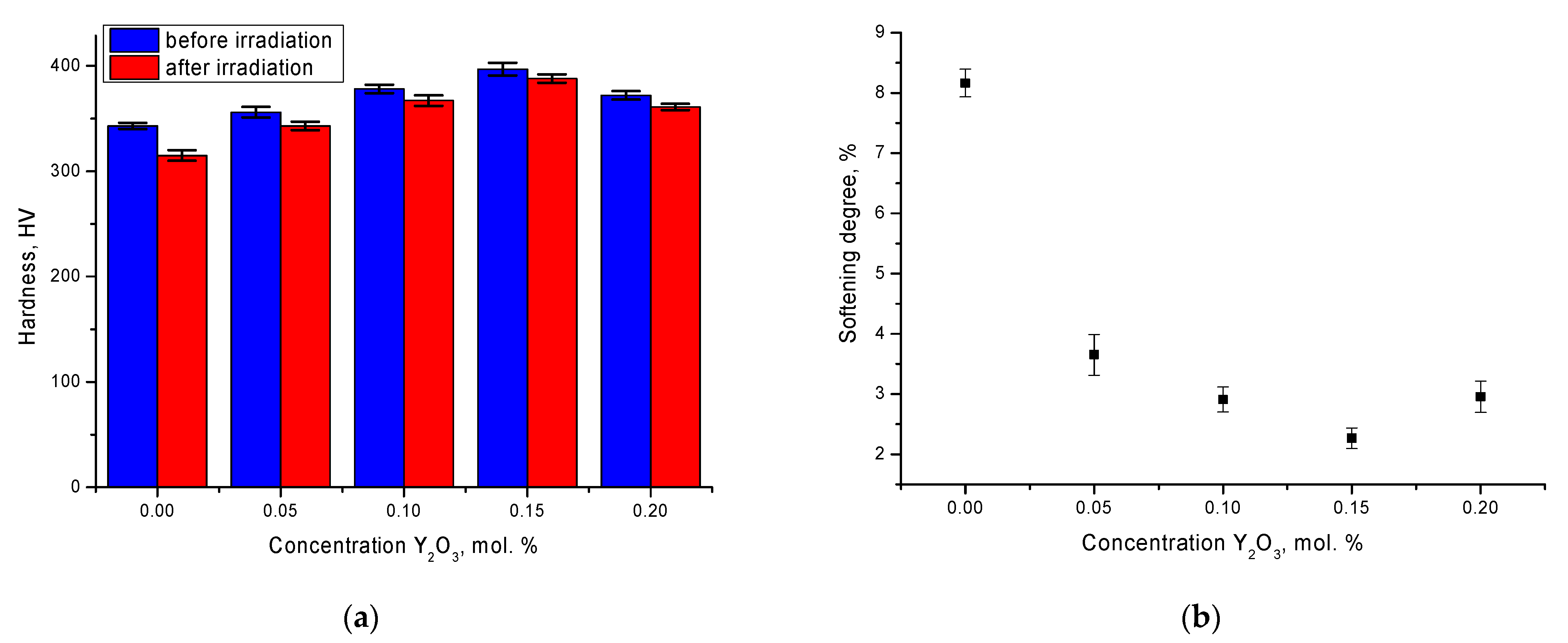
One of the important characteristics of microparticles that allows us to evaluate their prospects for use as inert matrix materials is their strength properties, in particular their hardness and resistance to cracking or softening as a result of external influences.
Figure 9 shows the results of changes in strength characteristics before and after irradiation.
From the data presented it is clear that an increase in dopant concentration leads to an increase in the hardness of the microparticles surface, which indicates an increase in strength properties. This behavior is due to a change in structural parameters, including a decrease in the crystal lattice volume, leading to an increase in density and a decrease in porosity. Based on the results of the change in hardness, the softening degree value was calculated, which makes it possible to assess the degree of resistance of the strength of irradiated near-surface layer to cracking and softening. At the same time, in the case of doped microparticle samples the decrease in hardness, and hence the softening degree is not more than 3–4%, while for the pristine sample hardness decrease is more than 8%, indicating low resistance to irradiation and subsequent accumulation of radiation damage. Therefore, it can be concluded from the obtained data that the doping of SeO2 with Y2O3 microparticles leads to an increase in strength and resistance to degradation and cracking as a result of external influences, which has a positive effect on the operating life of these structures as inert matrix materials.


 and
and 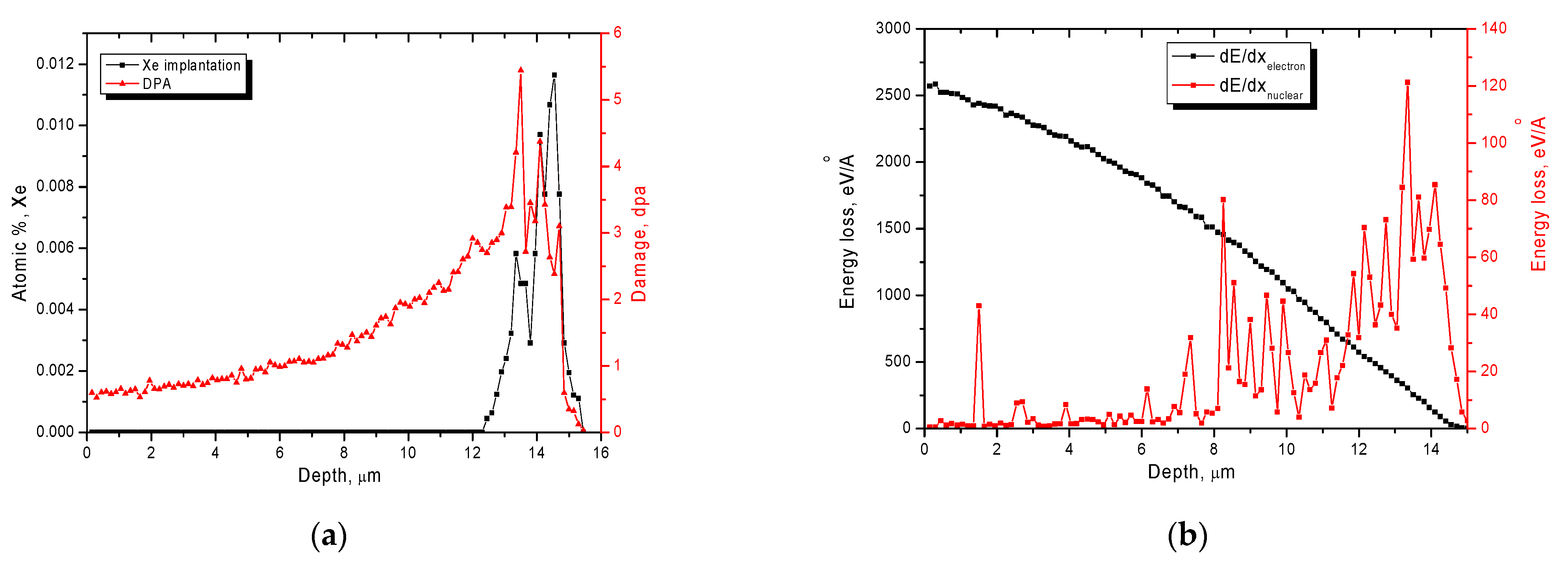


