Abstract
TiAl alloy was successfully brazed with Ag-CuO filler in air atmosphere under simple technical conditions. The wettability of a series of Ag-CuO fillers on TiAl was analyzed. Ag-2mol%CuO filler possessed good wetting behavior on TiAl alloy. The microstructure and mechanical properties of the brazed joints were investigated. Oxide layers can be found on both sides, which can be divided into external TiO2-rich layer and internal Al2O3-rich layer. The maximum shear strength of the joint was obtained at 1020 °C holding for 20 min.
1. Introduction
TiAl-based alloys have achieved considerable attention as one of the most promising high-temperature structural materials in aerospace and automotive industries due to their advantages of low density, high specific strength, high strength, and good high-temperature creep properties [1,2,3,4,5]. In the practical application of TiAl alloys, to manufacture complex components, it is necessary to realize reliable bonding between TiAl with itself or dissimilar materials.
The commonly used joining methods of TiAl alloys include fusion welding, diffusion bonding, and brazing. Fusion welding can realize the welding of TiAl alloys, but the crack tendency of direct welding is large. It is necessary to carefully control and optimize the welding parameters such as adopting preheating, slow cooling, or add interlayers to alleviate the crack tendency [6,7,8,9]. The diffusion bonding method, which is a kind of solid bonding method, can avoid the welding solidification cracks easily occurring in the fusion welding, and realize the effective joining of TiAl alloys. The drawback is that the long-term high temperature and high pressure in the diffusion bonding process may have adverse effects on the base metal [10,11]. To solve this problem, it is generally necessary to add an appropriate interlayer, and at the same time necessary to control the brittle compounds generated by the interlayer [12,13]. The most commonly used method to realize the joining of TiAl alloys is vacuum brazing. Ag-based fillers such as Ag-Cu and Ag-Cu-Ti [14,15,16,17] as well as Ti-based fillers often containing Cu, Ni and Zr [18,19,20,21] are most commonly used for vacuum brazing of TiAl. However, the commonly used brazing fillers are vulnerable to oxidation when the temperature is above 500 °C, leading to limited high temperature properties and long-term oxidation resistance of the brazed joints [22,23]. Moreover, vacuum equipment is required during brazing procedure to avoid the oxidation of the filler metal, which makes the costs of the method high and limits wider application. Metals can be joined in air by nanoparticles for electronical applications. However, the application temperature of the achieved joints is also quite limited [24,25]. A novel joining technique referred to as reactive air brazing (RAB) has been introduced to solve these problems in vacuum brazing. The method uses filler metal which contains a noble metal and an oxide component, possessing superior high-temperature oxidation resistance. Due to its good wettability, the RAB filler alloy system, especially Ag-CuO system, has received considerable attention in joining oxide ceramics [26,27,28,29,30]. Recently, some research has also focused on the RAB joining of metal–ceramic using Ag-CuO fillers, confirming the possibility of applying this method to metal brazing [31,32]. Thus, employing RAB to realize the joining of TiAl alloys would effectively improve the oxidation resistance of the joints. In addition, as the method is carried in air atmosphere, there would be no need to use complex vacuum equipment and simplify the brazing procedure, reducing equipment purchase and maintenance costs and increasing efficiency.
Therefore, in this paper, a series of Ag-CuO fillers were used to braze TiAl alloy in the air. The wettability of Ag-CuO fillers on TiAl alloys was studied. The effects of brazing temperature on the interfacial microstructure and joint strength were analyzed.
2. Materials and Methods
The joined base-metal was a γ-TiAl alloy with a nominal composition of Ti-46Al-2Cr-2Nb (at. %) obtained from Grinm Group Co. Ltd. The SEM image and the XRD pattern of TiAl alloy are shown in Figure 1. The alloy is mainly composed of lamellar γ-TiAl and α2-Ti3Al phases. TiAl alloy was cut into pieces of 5 mm × 5 mm × 5 mm and 15 mm × 5 mm × 5 mm. The surfaces of TiAl alloy were polished and ultrasonically cleaned for 10 min. The RAB filler consisted of Ag and CuO powders, which were purchased from Beijing Xingrongyuan Technology Co. Ltd. and had a purity of 99.95% and 99.9%, respectively. Table 1 lists the filler alloy composition used in this study. Ag and CuO powders were ball milled for 4 h to prepare the Ag-CuO fillers. The milled fillers were pressed into sheets with the thickness of ~100 μm. Then the filler sheet was sandwiched between two base metals. A normal load of 1 kPa was applied to the assembly to maintain a proper contact. The brazing procedure was conducted in air atmosphere in a muffle furnace (KSL-1200X, HF-Kejing). The assembly was heated to the brazing temperature at the rate of 10 °C/min, held at brazing temperature (970~1050 °C) for 20 min, and then furnace cooled to room temperature. In addition, a small amount of the Ag-CuO fillers of different compositions were individually placed on the surfaces of TiAl, which were then heated at the same rate to 1020 °C, holding for 20 min, to prepare the specimens for contact angle tests. The contact angle of the specimens after cooling to room temperature was measured.
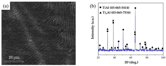
Figure 1.
(a) SEM image of the microstructure of TiAl substrate. (b) XRD pattern of TiAl substrate.

Table 1.
Filler alloy composition used in this study (mol%).
Scanning electron microscopy (SEM, FEI HELIOS NanoLab 600i), energy dispersive spectrometer (EDS), and X-ray diffraction (XRD, Bruker D8-Advance) were used to analyze the microstructure of the fillers and the brazed joints. Universal mechanical testing machine (Shimadzu AGXplus) was used to test the shear strength of the brazed joints with the loading rate of 0.5 mm/min. The schematic diagram of the shear strength test is shown in Figure 2. Three shear samples were examined for the joints brazed at each parameter.
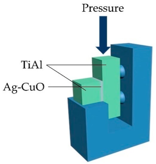
Figure 2.
Schematic diagram of shear strength test.
3. Results and Discussion
3.1. Wettability of Ag-CuO Fillers on TiAl
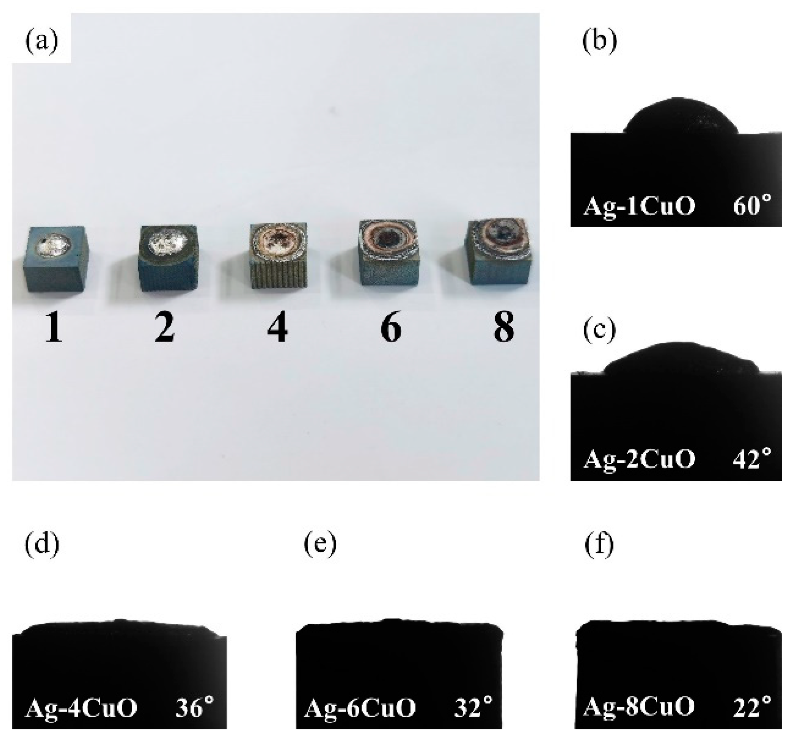
Since the wettability of the fillers on TiAl had an important influence on the brazing process, contact angle tests were carried out to evaluate the effect of the composition of the Ag-CuO fillers on their wetting performance on TiAl. Figure 3b–f shows the results of the tests. It can be seen that the contact angle decreased as the CuO content increases, indicating that the addition of CuO to the brazing filler improved its wettability on the TiAl substrate. However, Figure 3a indicates that the properties of the filler surface with high CuO content changed apparently. The metallic luster on the surface of the brazing filler had been lost and the middle of the filler became black. The surface presented annular diffusion bands, indicating that the filler diffused unevenly on the substrate. Figure 4 presents the microstructure of the Ag-6CuO surface. The EDS result of the spot is shown in Table 2, indicating that the black phase was mainly composed of Cu/Al oxides. The filler with high CuO content reacts greatly with the base metal, leading to huge aggregation of oxides. The uneven diffusion and the strong oxidation behavior have adverse effects on the subsequent brazing process.
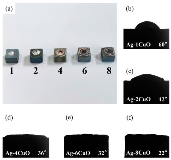
Figure 3.
Contact angles of Ag-CuO fillers on TiAl: (a) macroscopic appearance of the specimens, (b) Ag-1CuO, (c) Ag-2CuO, (d) Ag-4CuO, (e) Ag-6CuO, and (f) Ag-8CuO.
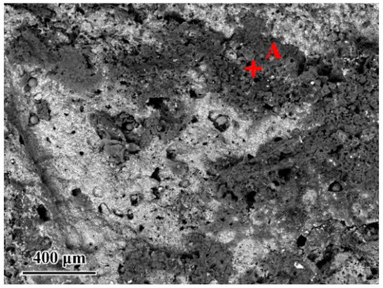
Figure 4.
Microstructure of the Ag-6CuO filler surface.
Table 2.
EDS result of the spot in Figure 4 (at. %).
Figure 5 shows the microstructure of the Ag-2CuO/TiAl cross section. The elements detected at each spot by EDS are listed in Table 3. The results indicates that Ti and Al oxides grew at the interface, which formed a good bonding with the filler alloy. The oxide layer can be divided into Al-rich layer on the lower side and Ti-rich layer on the upper side, and Cu can be detected in the Ti-rich part. According to the above results, Ag-2mol%CuO was selected as the filler alloy for brazing in subsequent experiments, and the brazing holding time was set to 20 min.
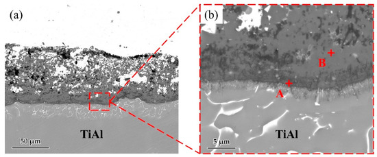
Figure 5.
(a) Microstructure of Ag-2CuO filler/TiAl cross section. (b) High magnification image of marked zone in Figure 3a.
Table 3.
EDS result of each spot in Figure 5 (at. %).
3.2. Typical Microstructure of TiAl Joint
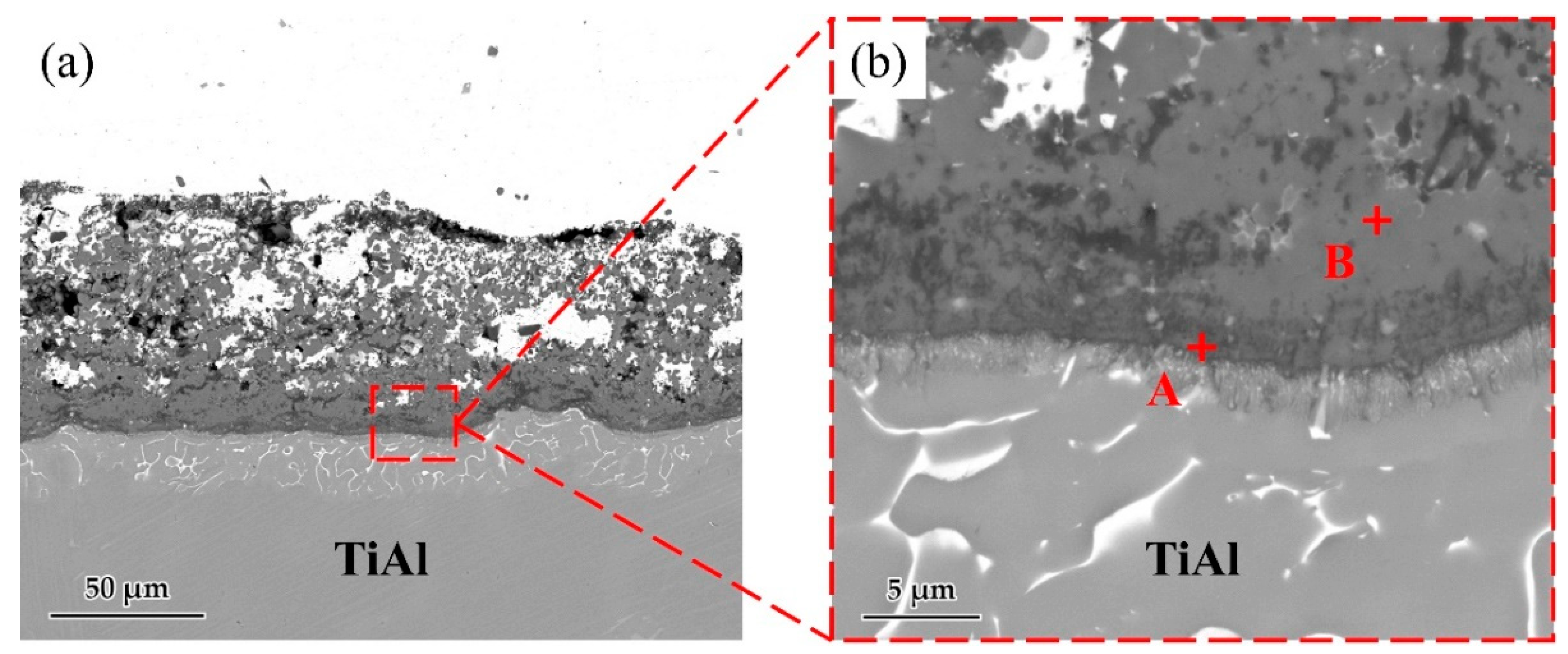
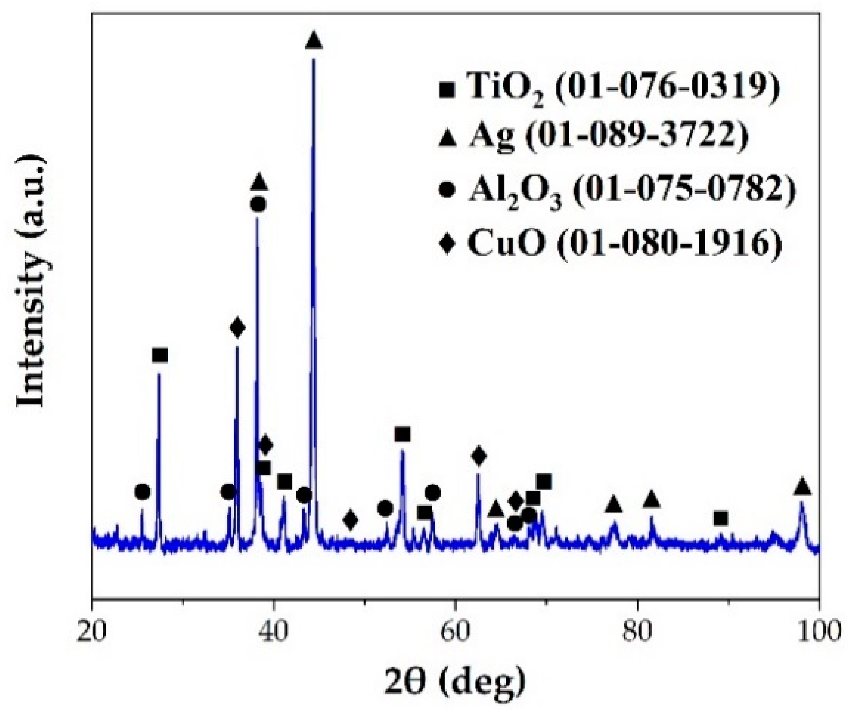
Figure 6 shows a typical interfacial microstructure of a brazed TiAl joint with an Ag-2CuO filler (1020 °C/20 min). It can be seen in Figure 6a that the TiAl alloy was soundly brazed without micro-cracks and a good bonding was achieved. Figure 6b presents the details of the interfacial microstructure of the joint. The results of EDS analysis at each spot in Figure 6b is shown in Table 4. Since the quantity of the light elements such as oxygen cannot be precisely determined by EDS, XRD analysis was carried out on the fracture of the joint. The XRD pattern obtained from the fracture of the TiAl joint under the same brazing condition after shear test is shown in Figure 7. TiO2, Al2O3, Ag, and CuO can be detected from the XRD pattern. The results indicated that the brazed joint was mainly composed of TiO2 and Al2O3, and there were multiphases in the oxidation layer. The dark Al-rich phase was mainly distributed inside, while the bright Ti-rich phase was mainly distributed outside.
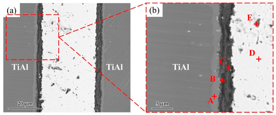
Figure 6.
(a) Microstructure of the joint brazed at 1020 °C for 20 min. (b) Enlarged image of the interface.
Table 4.
EDS result of each spot in Figure 6 (at. %).
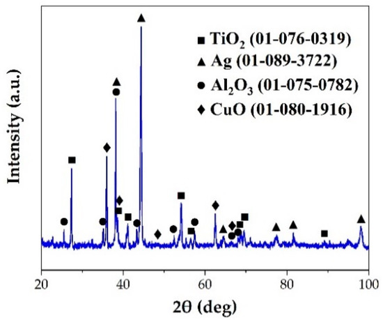
Figure 7.
XRD pattern of the fracture of the TiAl joint brazed at 1020 °C for 20 min.
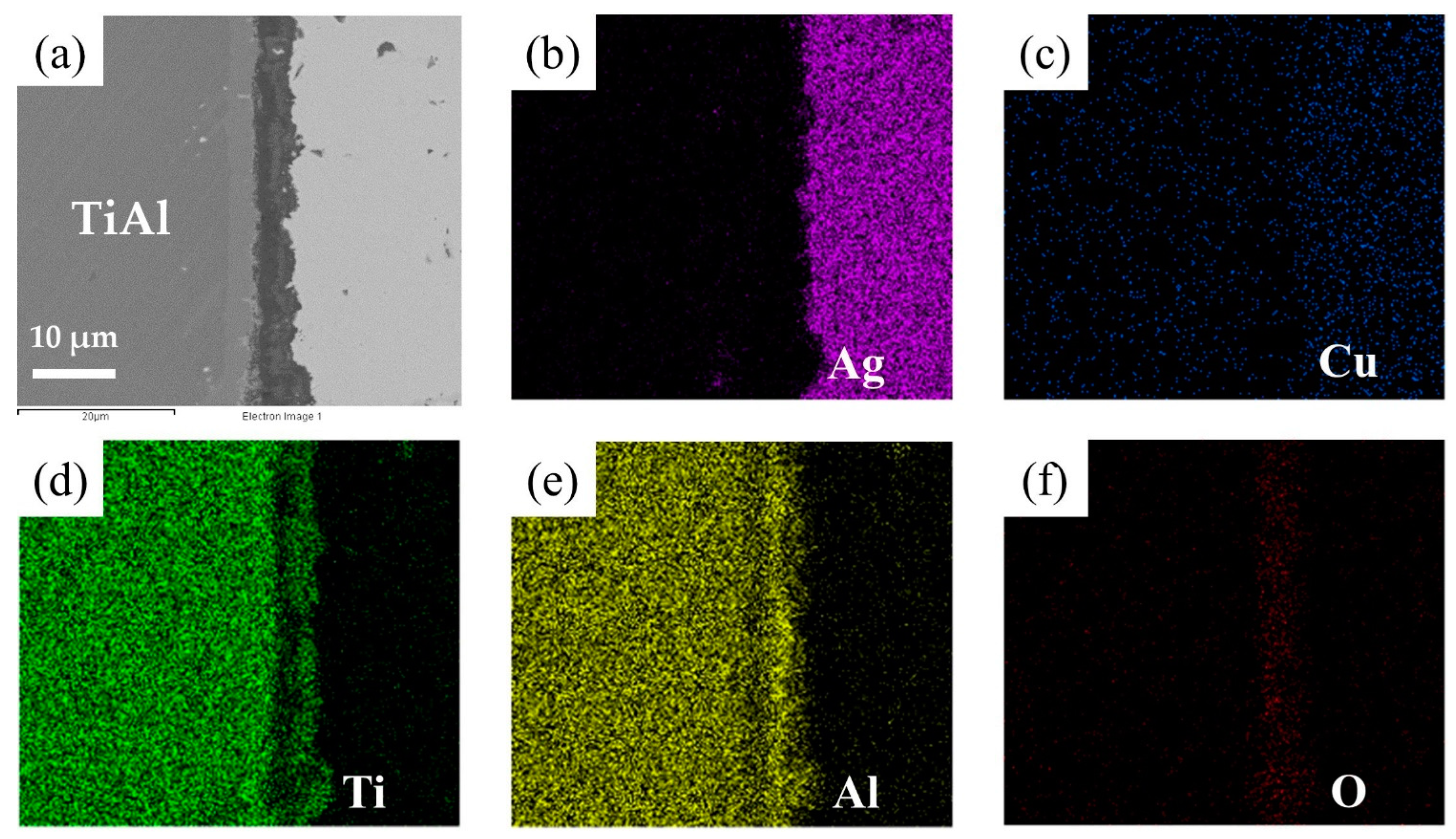
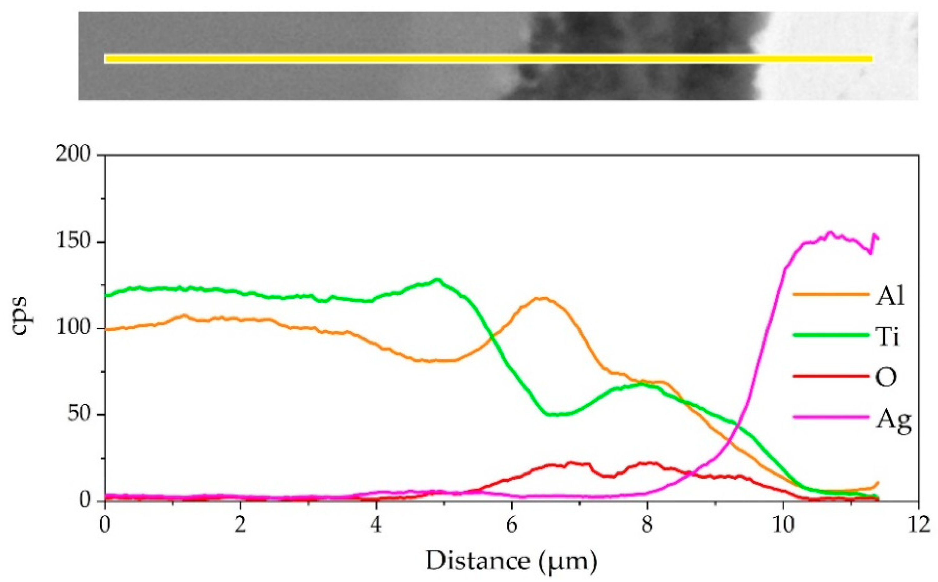
The element distribution at the interface of the joint is shown in Figure 8. As shown in Figure 8b,c, Ag and Cu elements mainly distributed in the middle of the brazing seam. Figure 8d–f shows that an oxidation layer mainly composed of Ti and Al oxides formed on the interface. A small amount of Ti and Al oxides diffused and dispersed in the middle of the brazing seam. A diffusion layer formed between the oxide layer and the substrate due to the outward diffusion of Ti and Al. In order to analyze the element distribution of the diffusion layer in detail, a line scanning of the interface was performed, as shown in Figure 9. The Ti/Al oxide layer can be divided into two parts. On the outer side Ti content was slightly higher than that of Al, and the inner side was an Al-rich phase. A phase with high Ti content appeared between the oxide layer and TiAl. Such distribution of outer TiO2-rich layer and inner Al2O3-rich layer correspond well with previous research [33,34,35]. The rapid external diffusion and high oxidation rate of Ti resulted in the higher TiO2 content in the outer layer and formed an Al-rich layer inside. At the same time the rapid oxidation of Ti led to low oxygen partial pressure inside the TiO2-rich layer. The higher aluminum content and lower oxygen partial pressure in this region led to the selective oxidation of Al, forming an Al2O3-rich layer. A part of the aluminum in this phase came from the outward diffusion of Al from the base metal, which resulted in a phase with high Ti content appearing between the oxide layer and TiAl.
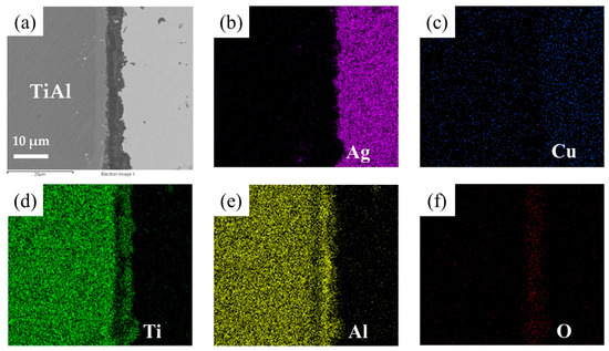
Figure 8.
EDS map scanning result of the interface: (a) SEM image of the interface. The corresponding EDS maps from Figure 6a: (b) Ti, (c) Al, (d) O, (e) Cu, (f) Ag.

Figure 9.
EDS line scanning result of the joint interface.
3.3. Effect of Brazing Temperature of TiAl Joints
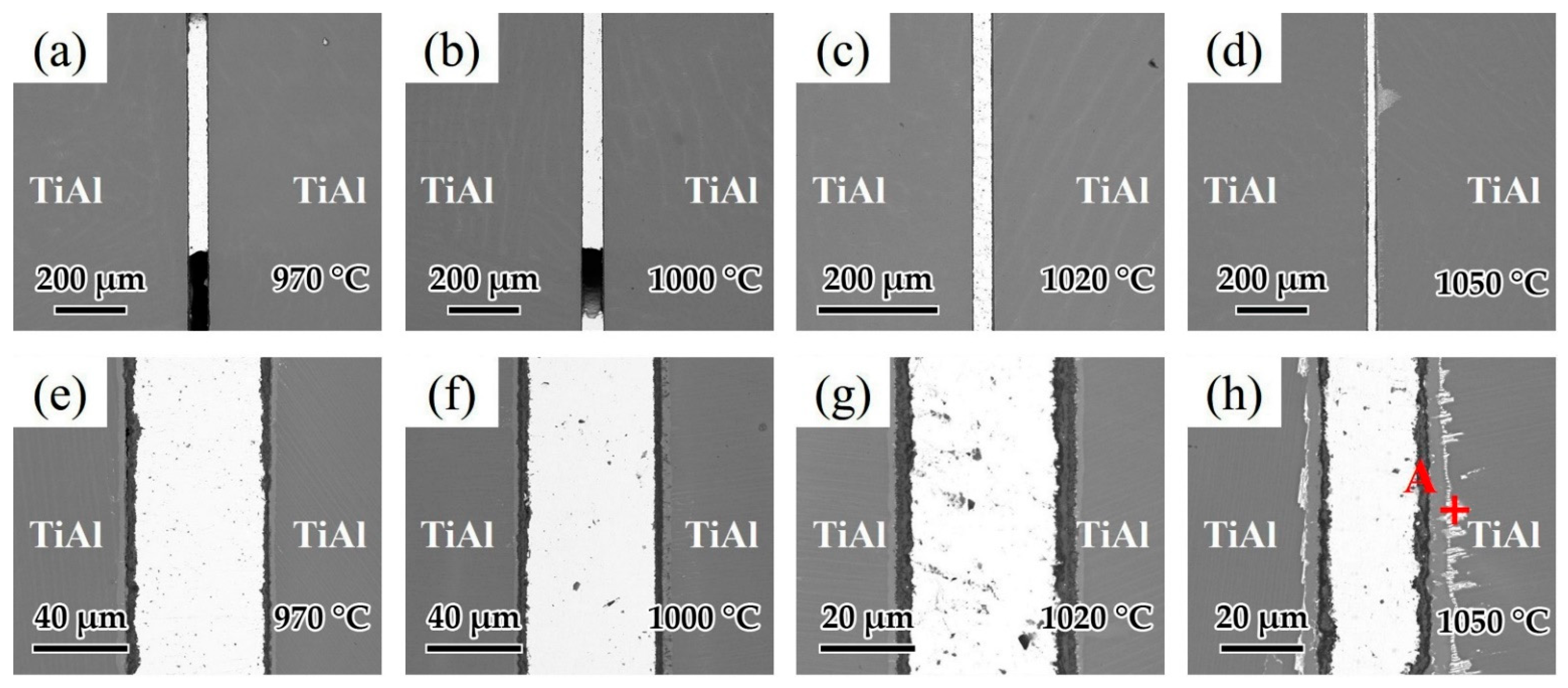
Brazing temperature is known as one of the most important factors affecting the brazing process. As a result, the influence of brazing temperature on the microstructure of the joints was analyzed. Figure 10a–d shows the interfacial structure of the joints at different brazing temperatures for 20 min. Figure 10a,b indicates that as the temperatures were low at 970 and 1000 °C, the fluidity of the brazing filler was relatively poor and voids could be observed in the joints. As shown in Figure 10c,d, when the brazing temperature was high enough, the fluidity of the brazing filler was improved and joints without macroscopic defects could be achieved. Figure 10e–h shows the detailed microstructure of the joints in Figure 10a–d. Figure 10e shows the microstructure of the joint brazed at 970 °C. It can be seen that the oxide distribution in the reaction layer was not uniform at such temperature, which may have an adverse effect on the wetting of Ag-CuO filler on the base metal. As the brazing temperature increased to 1000 and 1020 °C displayed in Figure 8f,g, the reaction layer formed with uniform thickness (~7 μm). When the brazing temperature was higher at 1050 °C shown in Figure 10h, the reaction layer became thicker (~10 μm), and a bright layer appeared between the base metal and the reaction layer. From the EDS analysis of the spot in Figure 10h shown in Table 5, it can be seen that this bright layer turned out to be Ag. Since it can be very difficult for Ag to diffuse through the 10 μm reaction layer, it can be indicated that cracks might be present in the reaction layer and Ag flows through the cracks to reach the interface between the reaction layer and the base metal. Some Ag shows further diffusion along grain boundaries into the TiAl base metal. Relatively, the thickness of the middle area of the brazing seam decreased because of the diffusion of Ag.
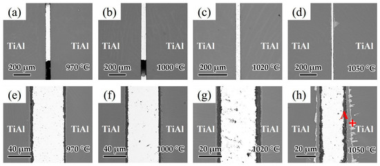
Figure 10.
Microstructure of joints at different brazing temperatures for 20 min: (a) 970 °C, (b) 1000 °C, (c) 1020 °C, (d) 1050 °C and the enlarged image of (a–d): (e) 970 °C, (f) 1000 °C, (g) 1020 °C, (h) 1050 °C.
Table 5.
EDS result of each spot in Figure 10h (at. %).
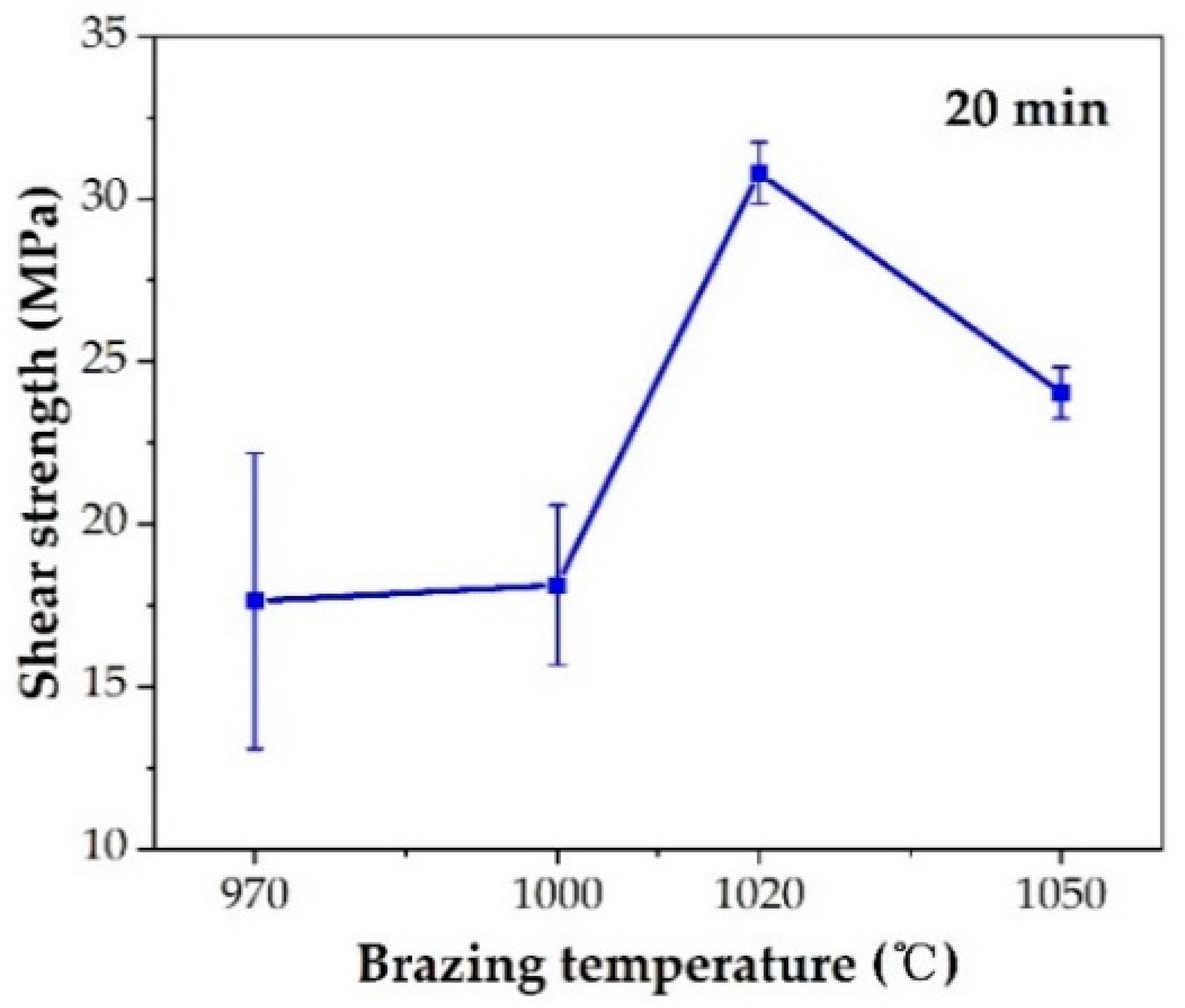
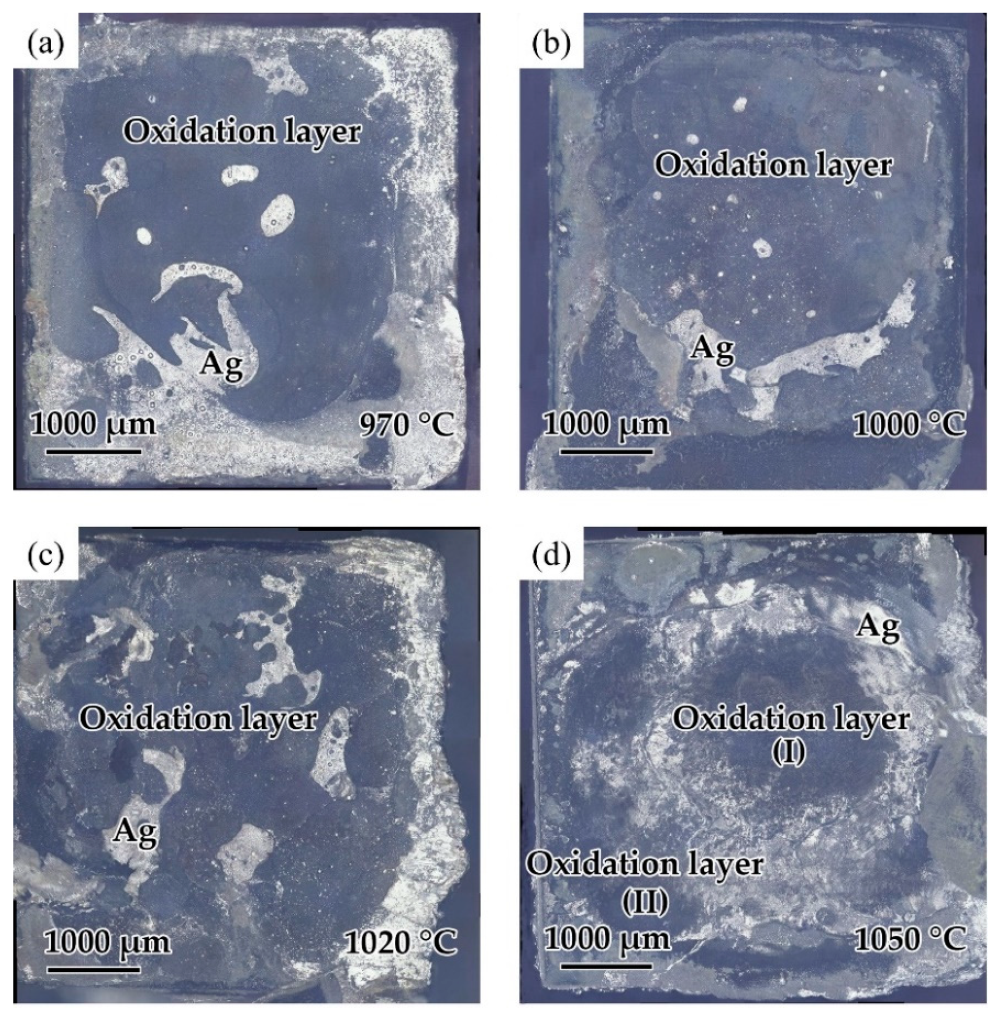
The effect of the brazing temperature on the shear strength of the brazed TiAl joints is shown in Figure 11. It can be indicated that the shear strength of the joints first increased and then decreased with the increase of brazing temperature. The shear strength value reached the maximum value of 30.8 MPa at the brazing temperature of 1020 °C. Combining with the above analysis of the microstructure of the joint, it can be concluded that the insufficient spread of the filler on the TiAl substrate at low temperature reduced the bonding strength of the joint. With the increase of brazing temperature, the brazing seam was gradually filled to form a complete joint, improving the strength. Figure 12 shows the fracture morphology of the joint brazed at different temperatures for 20 min. The fracture surface brazed at 970–1020 °C was flat and the surface was mainly the oxide layer with a small amount of Ag distributed on the surface. The fracture occurred mainly in the oxidation layer, indicating that the strength of the oxidation layer was lower than that of the brazing seam center mainly composed of Ag. The oxidation layer was the weak part in the joint. Figure 12d shows the fracture face of the joint brazed at 1050 °C. It can be seen that multiple layers presented on the fracture face. The two oxidation layers come from both sides of the brazing seam. As Ag can be found in the thicker oxide layers when the brazing temperature reached 1050 °C, it can be indicated that cracks might be generated, deteriorating the mechanical properties of the joint.
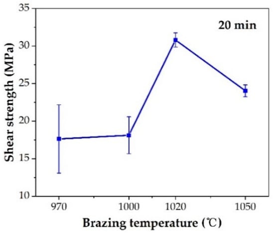
Figure 11.
Effect of brazing temperature on shear strength.
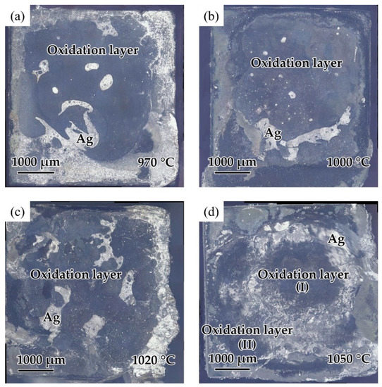
Figure 12.
Fracture surfaces of the joint brazed at different temperatures for 20 min: (a) 970 °C, (b) 1000 °C, (c) 1020 °C, (d) 1050 °C.
4. Conclusions
In summary, a novel method of brazing TiAl in air atmosphere with simple techniques was developed. TiAl alloy was successfully brazed using Ag-CuO filler. The wetting behavior of Ag-CuO fillers of different compositions were evaluated. The interfacial microstructure and joint properties of the brazed joints were investigated. The conclusions are summarized as follows:
- Ag-CuO fillers possessed sound wettability on TiAl alloy. The addition of CuO phase can effectively improve the wettability of the filler metal. Ag-2mol%CuO showed the best wetting result on TiAl.
- The typical microstructure of the TiAl brazed joint included the brazing seam zone in the middle of the joint mainly composed of Ag and oxidation layers between the brazing seam and TiAl, mainly composed of TiO2 and Al2O3. The distribution of the oxides was uneven, dividing the oxidation layer into the outer TiO2-rich layer and inner Al2O3-rich layer.
- The optimal brazing parameter was 1020 °C/20 min, at which the joint with good appearance, no obvious defects, and maximum shear strength of 30.8 MPa was obtained.
Author Contributions
Conceptualization, H.Y. and X.S.; methodology, X.S. and J.C.; investigation, H.Y.; data curation, H.Y.; writing—original draft preparation, H.Y.; writing—review and editing, X.S., C.L. and J.C.; visualization, H.Y. and C.L.; project administration, X.S.; funding acquisition, X.S., C.L. and J.C. All authors have read and agreed to the published version of the manuscript.
Funding
This research was funded by the Heilongjiang Provincial Postdoctoral Science Foundation LBH-Z18064, National Natural Science Foundation of China under Grant Nos. 52005131, China Postdoctoral Science Foundation under Grant 2019TQ0075, and the Heilongjiang Provincial Postdoctoral Science Foundation LBH-Z19142.
Institutional Review Board Statement
Not applicable.
Informed Consent Statement
Not applicable.
Data Availability Statement
Not applicable.
Acknowledgments
The authors gratefully acknowledge the financial support from the Heilongjiang Provincial Postdoctoral Science Foundation LBH-Z18064, National Natural Science Foundation of China under Grant Nos. 52005131, China Postdoctoral Science Foundation 2019TQ0075, and the Heilongjiang Provincial Postdoctoral Science Foundation LBH-Z19142.
Conflicts of Interest
The authors declare no conflict of interest.
References
- Appel, F.; Clemens, H.; Fischer, F.D. Modeling concepts for intermetallic titanium aluminides. Prog. Mater. Sci. 2016, 81, 55–124. [Google Scholar] [CrossRef]
- Kim, S.-W.; Hong, J.K.; Na, Y.-S.; Yeom, J.-T.; Kim, S.E. Development of TiAl alloys with excellent mechanical properties and oxidation resistance. Mater. Des. 2014, 54, 814–819. [Google Scholar] [CrossRef]
- Wu, X. Review of alloy and process development of TiAl alloys. Intermetallics 2006, 14, 1114–1122. [Google Scholar] [CrossRef]
- Clemens, H.; Mayer, S. Intermetallic titanium aluminides in aerospace applications–processing, microstructure and properties. Mater. High Temp. 2016, 33, 560–570. [Google Scholar] [CrossRef]
- Ding, J.; Zhang, M.; Liang, Y.; Ren, Y.; Dong, C.; Lin, J. Enhanced high-temperature tensile property by gradient twin structure of duplex high-Nb-containing TiAl alloy. Acta Mater. 2018, 161, 1–11. [Google Scholar] [CrossRef]
- Mallory, L.; Baeslack, W.; Phillips, D. Evolution of the weld heat-affected zone microstructure in a Ti-48AI-2Cr-2Nb gamma titanium aluminide. J. Mater. Sci. Lett. 1994, 13, 1061–1065. [Google Scholar] [CrossRef]
- Guoqing, C.; Binggang, Z.; Wei, L.; Jicai, F. Crack formation and control upon the electron beam welding of TiAl-based alloys. Intermetallics 2011, 19, 1857–1863. [Google Scholar] [CrossRef]
- Liu, J.; Dahmen, M.; Ventzke, V.; Kashaev, N.; Poprawe, R. The effect of heat treatment on crack control and grain refinement in laser beam welded β-solidifying TiAl-based alloy. Intermetallics 2013, 40, 65–70. [Google Scholar] [CrossRef]
- Cai, X.; Sun, D.; Li, H.; Meng, C.; Wang, L.; Shen, C. Dissimilar joining of TiAl alloy and Ni-based superalloy by laser welding technology using V/Cu composite interlayer. Opt. Laser Technol. 2019, 111, 205–213. [Google Scholar] [CrossRef]
- Çam, G.; İpekoğlu, G.; Bohm, K.-H.; Koçak, M. Investigation into the microstructure and mechanical properties of diffusion bonded TiAl alloys. J. Mater. Sci. 2006, 41, 5273–5282. [Google Scholar] [CrossRef]
- Du, Z.; Zhang, K.; Lu, Z.; Jiang, S. Microstructure and mechanical properties of vacuum diffusion bonding joints for γ-TiAl based alloy. Vacuum 2018, 150, 96–104. [Google Scholar] [CrossRef]
- Simões, S.; Viana, F.; Koçak, M.; Ramos, A.S.; Vieira, M.T.; Vieira, M.F. Diffusion bonding of TiAl using reactive Ni/Al nanolayers and Ti and Ni foils. Mater. Chem. Phys. 2011, 128, 202–207. [Google Scholar] [CrossRef]
- Xiaoguo, S.; Jian, C.; Jiakun, L.; Liyan, Z.; Jicai, F. Reaction-diffusion bonding of high Nb containing TiAl alloy. Rare Met. Mater. Eng. 2014, 43, 28–31. [Google Scholar] [CrossRef]
- Feng, J.; Dai, X.; Wang, D.; Li, R.; Cao, J. Microstructure evolution and mechanical properties of ZrO2/TiAl joints vacuum brazed by Ag–Cu filler metal. Mater. Sci. Eng. A 2015, 639, 739–746. [Google Scholar] [CrossRef]
- Shiue, R.K.; Wu, S.K.; Chen, S.Y. Infrared brazing of TiAl intermetallic using BAg-8 braze alloy. Acta Mater. 2003, 51, 1991–2004. [Google Scholar] [CrossRef]
- Shiue, R.K.; Wu, S.K.; Chen, S.Y. Infrared brazing of TiAl intermetallic using pure silver. Intermetallics 2004, 12, 929–936. [Google Scholar] [CrossRef]
- Song, X.; Zhao, Y.; Hu, S.; Cao, J.; Fu, W.; Feng, J. Wetting of AgCu-Ti filler on porous Si3N4 ceramic and brazing of the ceramic to TiAl alloy. Ceram. Int. 2018, 44, 4622–4629. [Google Scholar] [CrossRef]
- Simoes, S.; Soares, A.; Tavares, C.J.; Guedes, A. Joining of TiAl Alloy Using Novel Ag-Cu Sputtered Coated Ti Brazing Filler. Microsc. Microanal. 2019, 25, 192–195. [Google Scholar] [CrossRef] [PubMed]
- Lee, S.; Wu, S.; Lin, R. Infrared joining of TiAl intermetallics using Ti-15Cu-15Ni foil—I. The microstructure morphologies of joint interfaces. Acta Mater. 1998, 46, 1283–1295. [Google Scholar] [CrossRef]
- Lee, S.; Wu, S.; Lin, R. Infrared joining of TiAl intermetallics using Ti-15Cu-15Ni foil—II. The microstructural evolution at high temperature. Acta Mater. 1998, 46, 1297–1305. [Google Scholar] [CrossRef]
- Qiu, Q.; Wang, Y.; Yang, Z.; Hu, X.; Wang, D. Microstructure and mechanical properties of TiAl alloy joints vacuum brazed with Ti–Zr–Ni–Cu brazing powder without and with Mo additive. Mater. Des. 2016, 90, 650–659. [Google Scholar] [CrossRef]
- Cao, J.; Si, X.; Li, W.; Song, X.; Feng, J. Reactive air brazing of YSZ-electrolyte and Al2O3-substrate for gas sensor sealing: Interfacial microstructure and mechanical properties. Int. J. Hydrog. Energy 2017, 42, 10683–10694. [Google Scholar] [CrossRef]
- Lee, D.; Woo, J.; Park, S. Oxidation behavior of Ag-Cu-Ti brazing alloys. Mater. Sci. Eng. A 1999, 268, 202–207. [Google Scholar] [CrossRef]
- Wang, Q.; Zhang, S.; Lin, T.; Zhang, P.; He, P.; Paik, K.-W. Highly mechanical and high-temperature properties of Cu–Cu joints using citrate-coated nanosized Ag paste in air. Prog. Nat. Sci. Mater. Int. 2021, 31, 129–140. [Google Scholar] [CrossRef]
- Zhang, S.; Wang, Q.; Lin, T.; Zhang, P.; He, P.; Paik, K.-W. Cu-Cu joining using citrate coated ultra-small nano-silver pastes. J. Manuf. Process. 2021, 62, 546–554. [Google Scholar] [CrossRef]
- Kim, J.; Hardy, J.S.; Weil, K.S. Silver-copper oxide based reactive air braze for joining yttria-stabilized zirconia. J. Mater. Res. 2005, 20, 636–643. [Google Scholar] [CrossRef]
- Kim, J.Y.; Hardy, J.S.; Scott Weil, K. Effects of CuO content on the wetting behavior and mechanical properties of a Ag–CuO braze for ceramic joining. J. Am. Ceram. Soc. 2005, 88, 2521–2527. [Google Scholar] [CrossRef]
- Raju, K.; Yoon, D.-H. Reactive air brazing of GDC–LSCF ceramics using Ag–10 wt% CuO paste for oxygen transport membrane applications. Ceram. Int. 2016, 42, 16392–16395. [Google Scholar] [CrossRef]
- Si, X.; Cao, J.; Song, X.; Qu, Y.; Feng, J. Reactive air brazing of YSZ ceramic with novel Al2O3 nanoparticles reinforced Ag-CuO-Al2O3 composite filler: Microstructure and joint properties. Mater. Des. 2017, 114, 176–184. [Google Scholar] [CrossRef]
- Si, X.; Cao, J.; Song, X.; Wang, Z.; Wang, Z.; Feng, J. Evolution behavior of Al2O3 nanoparticles reinforcements during reactive air brazing and its role in improving the joint strength. Mater. Des. 2017, 132, 96–104. [Google Scholar] [CrossRef]
- Tillmann, W.; Anar, N.B.; Wojarski, L. Mechanical behavior of reactive air brazed (RAB) Crofer 22 APU-Al2O3 joints at ambient temperature. SN Appl. Sci. 2020, 2, 809. [Google Scholar] [CrossRef] [Green Version]
- Wang, X.Y.; Si, X.Q.; Li, C.; Guo, X.J.; Cao, J. Joining the BaZr0.1Ce0.7Y0.1Yb0.1O3-delta Electrolyte to AISI 441 Interconnect for Protonic Ceramic Fuel Cell Applications: Interfacial Microstructure and Long-Term Stability. ACS Appl. Energ. Mater. 2021, 4, 7346–7354. [Google Scholar] [CrossRef]
- Lang, C.; Schütze, M. TEM investigations of the early stages of TiAl oxidation. Oxid. Met. 1996, 46, 255–285. [Google Scholar] [CrossRef]
- Maurice, V.; Despert, G.; Zanna, S.; Josso, P.; Bacos, M.-P.; Marcus, P. XPS study of the initial stages of oxidation of α2-Ti3Al and γ-TiAl intermetallic alloys. Acta Mater. 2007, 55, 3315–3325. [Google Scholar] [CrossRef]
- Swadźba, R.; Marugi, K. STEM investigations of γ-TiAl produced by additive manufacturing after isothermal oxidation. Corros. Sci. 2020, 169, 108617. [Google Scholar] [CrossRef]


Publisher’s Note: MDPI stays neutral with regard to jurisdictional claims in published maps and institutional affiliations. |
© 2021 by the authors. Licensee MDPI, Basel, Switzerland. This article is an open access article distributed under the terms and conditions of the Creative Commons Attribution (CC BY) license (https://creativecommons.org/licenses/by/4.0/).