Abstract
This study demonstrates controllable random lasing emissions in a dye-doped nematic liquid crystal (DDNLC)-infiltrated microcapillary. The emission wavelength of the micro tube laser can be adjusted by changing the focusing position of the pumped pulses on the center or the periphery of the liquid crystal region of the microcapillary. In addition, with doping azo-dyes in the DDNLC of the micro tube laser, optical controllability of the lasing intensity and wavelength can be further achieved. The controllable micro tube laser may find highly widespread photonic applications in multicolor emitting sources, and vibration and UV sensors.
1. Introduction
The development of micro lasers has attracted increasing interest recently, not only because of the fundamental discussions of spontaneous emission and photon localization in artificially fabricated structures taking place, but also for their potential applications in integrated photonics. So far, micro lasers have been achieved in the base of different dielectric microstructures which can confine light in a small and compact cavity such as micropillars [], micro-disks [], microtoroids [], and micro droplets []. Micro lasers with cylindrical or spherical symmetry are particularly noteworthy because their quality is much better than that of the typical Fabry–Perot resonator []. The rays in this kind of micro resonator can reflect at a near-grazing angle and thus hug the interior boundary of the resonator, resulting in whispering gallery modes (WGMs) []. However, it is highly desirable to improve the tunability of micro lasers for further applications.
Liquid crystal (LC) is an excellent material for applications on tunable cavities and lasers because of its optical response to external stimuli []. Lasing emissions from self-organized chiral liquid crystals are the most popular liquid crystal lasers and have been widely demonstrated [,,,,]. Not only liquid crystals with chirality and periodic structures can be employed as mirrorless cavities for tunable lasing emissions—nematic liquid crystals (NLCs) can be also applied on tunable lasing emissions, with the aid of external cavities [,] or by recurrent multi-scattering [,,]. Light localization and random lasing emissions can be achieved in an NLC system if the NLC region is thick enough to support recurrent multi-scattering of fluorescence [,,]. Random lasing emissions from NLCs have been realized in various geometric containers, such as wedge cells [], nets [], and microcapillaries []. Microcapillaries can be adopted for cavities supporting WGM lasing emissions because of their cylindrical structures []. In addition, the boundary constraints of the container could lead to the wavelength modulation of NLC-based random lasing []. Therefore, it is possible to produce a micro tube laser with tunable and multiple lasing wavelengths by the combination of NLCs and a microcapillary.
This study demonstrates a simple way to fabricate an all-optically controllable micro tube laser based on a dye-doped nematic liquid crystal (DDNLC)-infiltrated microcapillary. Since NLC is partially disordered and can provide multi-scattering as well as weak localization of light, random lasing emission can be generated in a DDNLC-infiltrated microcapillary. Furthermore, the lasing wavelength will change due to the boundary constraints when the pumped pulse is focused near the interior surface of the microcapillary. Therefore, by adjusting the pumped region, the wavelength of the random lasing emission can be modulated. Furthermore, with the addition of azo-dye, all the characteristics of the micro laser can be optically controlled. The intensities of the random lasing emission can be controlled by successively irradiating one UV light (365 nm) and one green light (532 nm). The mechanism of complete optical controllability is attributed to the isothermal phase transitions of the DDNLCs. In addition to the intensity, the wavelength of the lasing emission can also be switched with the completely optically induced isothermal phase transition of the DDNLCs.
2. Materials and Methods
Two DDNLC mixtures were prepared in this paper. DDNLC1 was composed of NLC (MDA03-3970, ne = 1.6309 and no = 1.4987 for 589.3 nm at 20 °C, from Merck) and laser dye (P597, from Exciton) in a weight ratio of 99.5:0.5. The DDNLC2 mixture included 91.5 wt% of NLC (MDA03-3970 and 5CB in an equal weight ratio, 5CB, ne = 1.7063 and no = 1.5309 for 589.3 nm at 20 °C, is from Sigma-Aldrich (St. Louis, MO, USA)), 0.5 wt% of laser dye (P597), and 8 wt% of azo-dye (4-Methoxyazobenzene, from Sigma-Aldrich). The two mixtures were stirred by magnetic stirrers at their isotropic states for 3 h to ensure that all the materials were mixed homogeneously and then slowly cooled down to the temperature. The two mixtures were infiltrated into two empty capillary tubes made of precision-bore glass (Microcap 1.0UL, from Drummond Scientific Company (Broomall, PA, USA)) with inner and outer diameters of 200 and 660 μm via capillary effect for capillary tube laser 1 and capillary tube laser 2. The refractive index of the glass capillary was around 1.473. Figure 1 displays the experimental setup for examining the lasing emissions in DDNLC-infiltrated capillary tube lasers. The tube laser was pumped by a Q-switch Nd:YAG second harmonic generation (SHG) pulse laser with a wavelength of 532 nm, pulse duration of 8 ns, and repetition rate of 10 Hz. The pulse energy could be controlled with the combination of a half-wave plate and a polarizer. Another half-wave plate behind the polarizer was utilized to control the polarization direction of the pulse beam to be parallel to the axis of the capillary tube sample to obtain the maximum excitation efficiency of the DDNLC. One 1:1 non-polarizing beam splitter was set following the second polarizer to divide the incident pulse beam into two beams. One of the two beams was focused on the capillary tube laser with a spherical lens, with a focal length of 20 cm for the excited lasing emission. A polarizer and a fiber-optic probe of a fiber-based spectrometer (Jaz-Combo-2, Ocean Optics (Dunedin, FL, USA), resolution: ~0.9 nm) were set to measure the polarization and the relative intensity of the lasing output. A notch-filter of 532 nm was placed in front of the fiber-based spectrometer to avoid the excess pulse laser from entering the spectrometer. The other beam was received by a power meter to measure the energy of the incident pumped pulses. For optical control of the lasing emissions of the capillary tube laser, two other light sources—one UV lamp (emission peak at 365 nm, Light-Welder PC-3, DYMAX (Torrington, CT, USA)) and one continuous wave (CW) diode-pumped solid state (DPSS) laser with a wavelength of 532 nm—were set to illuminate the DDNLC2-infiltrated capillary tube. The intensities of the UV and the DPSS laser beams were fixed at 58.95 and 267.38 mW/cm2, respectively.
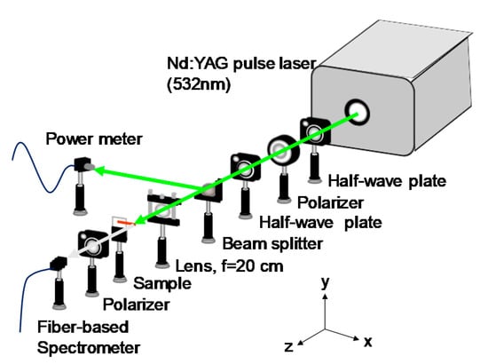
Figure 1.
Experimental setup for measuring the lasing emissions.
3. Results and Discussion
3.1. Pumped-Position Controlled Random Lasing Emissions
The excited lasing patterns of the capillary tube laser 1 are shown in Figure 2. The images of the lasing patterns were displayed on a curved screen and captured by a camera. A tiny hole was drilled in the curved screen for the pulse laser to pass through the screen and pump the capillary tube laser, which was put in the center of the curvature of the curved screen, as shown in Figure 2. The polarization of the pulse laser was set to be in parallel with the axial direction of the capillary tube for the optimal pumped condition. When the sample was set exactly on the focus of the lens, the pattern of the excited lasing emission shows two yellow spots along the normal direction on the screen, as shown Figure 2a. When the focused pulse beam was adjusted to deviate from the center of the DDNLC-infiltrated capillary tube, instead of the yellow spots, the pattern of the excited lasing emission showed an orange stripe on the curved screen, as shown in Figure 2b.
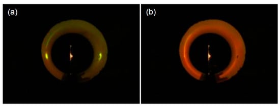
Figure 2.
Lasing patterns of the DDNLC1-infiltrated capillary tube when the tube was pumped (a) on-center and (b) off-center.
Figure 3a shows the emission spectra of the capillary tube laser pumped with various pulse energies on-center. Only weak fluorescence can be excited if the pumped energy of the incident pulse is low. When the pumped energy of the incident pulse gradually increased, the emission spectra exhibited multiple peaks around 580 nm. The multi-peak emissions shown in Figure 3a were confirmed as random lasing emissions since we got a similar result when the DDNLC was placed in a wedge cell, which does not support the existence of a Fabry–Perot resonant mode, and for which the fluorescence can be enhanced only via the closed loop formed by the random scattering []. To further verify that no Fabry–Perot effect occurred in the random lasing generation, the Fourier power transforms of the lasing spectra (the red curve) of Figure 3a were calculated and are presented in the inset. It is well-known that Fourier analyses performed for random laser spectra are represented on the 1/λ scale, so the frequencies of the obtained Fourier spectra are on the micrometer scale []. The nonperiodic and broad spectral components shown in the inset of Figure 3a indicate that the random lasing generation did not result from the Fabry–Perot effect. The generation of random lasing emission in the DDNLC micro tube is attributed to the recurrent multi-scattering and weak localization of fluorescence photons when the DDNLC region is thick enough []. In this paper, the inner diameter of the capillary tube was 200 μm, which is sufficient to show spatial fluctuation in the orientational order and dielectric tensor of LCs [,]. The central wavelength of the random lasing emission of the DDNLC micro tube was around 580 nm because the laser dye P597 has the lowest energy threshold at the wavelength around 580 nm when it is doped with nematic liquid crystals []. The variations in the peak intensity and full-width at half-maximum (FWHM) of the random lasing emission profile on the incident pumped energy are summarized in Figure 3b. It can be clearly observed that when the incident pumped energy exceeded 1 µJ/pulse, the peak intensity of the random lasing emission clearly increased, while the FWHM of the emission spectrum decreased sharply. That is, the energy threshold of the random lasing emission was around 1 µJ/pulse. Figure 3c shows the lasing spectra of the capillary tube laser when the pumped pulse was focused on DDNLC near the glass sheath of the capillary tube with various pulse energies. Similarly, only weak fluorescence could be excited if the pumped energy of the incident pulse was low. When the pumped energy of the incident pulse beam gradually increased, the emission spectra exhibited multi-peaks around 600 nm and the peak intensity increased abruptly. One possible reason for the wavelength shifting from 580 nm to 600 nm is due to boundary constraints at the capillary wall []. The boundary constraints have influence on the order parameters of the dyes and the liquid crystal molecules, the total gain profile, and thus, the lasing wavelength []. The variations in the peak intensity and FWHM of the lasing emission profile on the incident pumped energy are summarized in Figure 3d. Figure 3d indicates that when the incident pumped energy exceeded 0.8 µJ/pulse, the peak intensity of the lasing emission clearly increased, while the FWHM of the emission spectrum decreased sharply. Therefore, we can define the energy threshold of the lasing emission as 0.8 µJ/pulse.
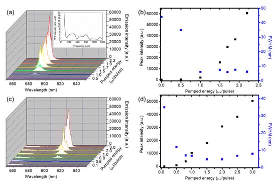
Figure 3.
Emission spectra when the pumped pulse was focused (a) on the center and (c) near the glass sheath of the capillary tube laser with various pumped energies, respectively. Peak intensity and FWHM versus incident pumped energy of (a) and (c) are shown in (b) and (d), respectively. The inset of (a) shows the calculated results of the Fourier power transform of the lasing emission spectra.
As described in Figure 2 and Figure 3, the wavelength of the lasing emission depends on the pumped light being focused on or deviating from the center of the DDNLC region. Here, we put the DDNLC-infiltrated capillary tube on a translation stage to further investigate the position-dependent lasing emission. Referring to Figure 1, the DDNLC-infiltrated capillary tube was placed on the xy-plane and aligned along the x-axis, and the incident pulse was aligned to propagate along the z-axis. The pumped location, and thus the lasing emission, can be adjusted by moving the capillary tube along the z-axis or y-axis.
First, we discuss the case of adjusting the relative distance between the capillary tube laser and the lens by moving the capillary tube along the z-axis and defining it as the shifted distance. As shown in Figure 4a, if the shifted distance between the center of the tube and the lens was equal to the focal length, the random lasing emission with a central wavelength of 580 nm (green curve) could be excited. If the focused spot was moved away from the center of the capillary tube by 1 mm, the intensity of the random lasing emission decreased, as shown by the blue and yellow curves. If the shifted distance between the focused spot and the center of the capillary was 2 mm, a weak emission with a central wavelength of 600 nm could be excited, as shown by the orange and cyan curves. The stronger lasing emission (red and violet curves) could be measured if the center of the capillary deviated from the focused spot by 3 mm. It should be noted that the pumped pulse propagated through the capillary, which has spherical boundaries and can be regarded as a lens. Therefore, the shifted distance between the lens and the capillary tube was not equal to the variation of the focused position. After observing the variation of the lasing emission by adjusting the pumped region along the z-axis, the variation of the lasing emission by changing the pumped location along the y-axis was also of interest. The experimental results on the variation of lasing emission with adjustment of the pumped region along the y-axis is shown in Figure 4b. The central wavelength of the random lasing emission is located at 580 nm (green curve), which occurred when the focused spot was in the center of the capillary tube. If the focused spot was moved up or down from the center of the capillary cylinder by 10 μm, weak lasing emissions with central wavelengths of 580 and 600 nm could be observed simultaneously (blue and yellow curves). Since the spherical boundaries of the capillary can be regarded as a lens with spherical aberration, which indicates that the light passing through along the central axis and off-axis will be focused on different spots, the random lasing emission at the excited location along with the z-axis (along the central axis) was a little bit different to that of y-axis (off-axis). By moving the focused spot further away from the center of the capillary cylinder, the intensities of the lasing emissions with central wavelengths of 580 and 600 nm decreased and increased, respectively.
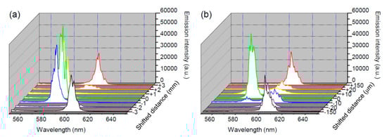
Figure 4.
Lasing spectra of the DDNLC-infiltrated capillary tube at different excited locations along the (a) z-axis and (b) y-axis. The pumped energy was 2 μJ/pulse here.
3.2. Complete Optical Control of Lasing Emissions
When the DDNLC1 was replaced by DDNLC2, which included 8 wt% of azo-dye, the properties of the micro tube laser could be further controlled via complete optical control. The random lasing emission in the DDNLC2-infiltrated micro tube could be controlled, making it decrease with the irradiation of the UV light (365 nm) at various irradiation times tUV = 0, 10, 20, 30, and 40 s, as shown in Figure 5a. Here, the irradiated intensity of the UV light was fixed to 59 mW/cm2 and the pumped energy was fixed to 9 μJ/pulse. Following the UV irradiation, one green light (532 nm) with a fixed intensity of 267.4 mW/cm2 was employed to irradiate the tube with irradiating times of tG = 0, 5, 15, and 20 s, as shown in Figure 5b. The intensity of the random lasing emission could be controlled and made to return to its original value by irradiating the green light for 20 s. The variation of the random lasing intensity was attributable to the UV- and green light-induced isothermal phase transitions between the nematic and isotropic phase of the DDNLCs, via isomerization of the azo-dye. The azo-dye, 4MAB, stably exists in trans-form in darkness. The trans-4MAB dyes were roughly aligned with the molecules of the LC via the guest–host effect in the DDNLC. The trans-4MAB dyes absorbed UV light (365 nm) and transformed to a bent cis-form, resulting in the disorder of the LC host. By increasing the time of UV irradiation, tUV, the concentration of the cis-form increased such that the phase of the LCs gradually changed from nematic to isotropic isothermally []. This process caused the spatial nonuniformity of the order [δS = S(r + δr)–S(r)], and thus of the dielectric tensor [δε = ε(r + δr) − ε(r)] of the LCs, to gradually decrease from a nonzero (δS ≠ 0 and δε ≠ 0 at nematic phase) to a zero (δS = 0 and δε = 0 at isotropic phase) value, where δr, δS and δε denote the differential displacement, differential order and differential dielectric tensor of the LCs between two adjacent local micro-domains of the LCs, respectively. Therefore, the local multiple micro-domain of the LCs experienced by the propagation of fluorescence photons gradually disappeared, and thus the recurrent multi-scattering of the fluorescence decreased. When the cis-4MAB dyes were exposed to green light, the bent cis-4MAB transformed back to a trans-form and the DDNLC consequently changed back to the nematic phase from the isotropic phase. With the reappearance of the nematic phase, the uniform orientations of the LCs, and thus the recurrent multi-scattering of the fluorescence, resulted in the recovery of random lasing emissions [].
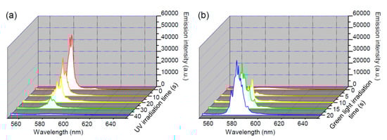
Figure 5.
Variations of the random lasing emission in the DDNLC2-infiltrated micro tube with (a) UV light irradiation, and (b) green light illumination.
The UV-induced isothermal phase transition of the DDNLC-infiltrated micro tube was observed with the aid of a transmitted polarizing optical microscope (T-POM) with crossed polarizers. As shown in Figure 6, the angle between the transmission axis of the polarizer and the axis of the capillary cylinder was 45°. By increasing the duration of the UV light irradiation, tUV, from 0 to 40 s, the transmission decreased from the bright to the dark state, as shown in Figure 6a. On the contrary, by increasing the duration of the green light irradiation, tG, from 0 to 20 s, the transmission recovered back to the bright state, as shown in Figure 6b. These results coincide with the mechanisms that cause the reversible variation of the random lasing intensity—that is, the UV- and green beam-irradiation, which induce isothermal nematic to isotropic and isotropic to nematic phase transitions of LCs via trans–cis and cis–trans isomerizations of azo-dye, respectively. During the photo-induced phase transition, the variation in temperature of the DDNLC-infiltrated micro tube was monitored with a thermal imager (Fluke, Ti10). The temperature of the micro tube only increased from 23.8 °C to 27.9 °C after irradiation with UV for 50 s, as shown in Figure 6c,d. The final temperature, 27.9 °C, was much lower than the temperature of the clearing point of the DDNLC2, which was about 50 °C. This result indicates that no thermal-induced phase transition occurred during the UV irradiation process. As a result, we can ascertain that the complete optical control of the lasing emission was not caused by thermal effects but by the effects of photoisomerization.
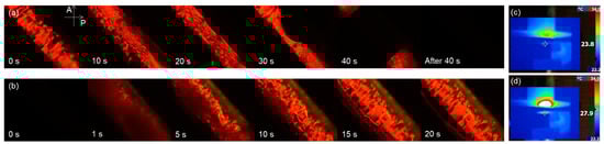
Figure 6.
T-POM images of the DDNLC2-infiltrated micro tube under the illumination of (a) UV light, and (b) green light. The thermal images of the DDNLC-infiltrated micro tube (c) before and (d) after UV illumination.
As discussed in Section 3.1, the wavelength of the lasing emission can be changed from 580 nm to 600 nm if the focused pulse deviates from the center of the micro tube. In this section, we adjusted the position of the focused spot (off-center pumped) to generate a lasing emission with a central wavelength of 600 nm. When the micro tube was irradiated by the UV light at various irradiation times tUV = 0, 10, 20, 30, 40, and 45 s, the variations of the emission spectra were as shown in Figure 7a. At tUV = 0, 10, and 20 s, the central wavelength of the lasing emission was located around 600 nm and its intensity gradually decreased. At tUV = 30 s, two groups of lasing emissions with main wavelengths located at 600 nm and 620 nm could be observed on the spectrum. At tUV = 40 and 45 s, the central wavelength of the lasing emission was at 620 nm and the emission intensity gradually increased with tUV. Following the UV irradiation, the micro tube was irradiated by green light with the irradiation time tG = 0, 5, 15, 20, and 25 s to trigger the cis to trans isomerization of the azo-dye. As shown in Figure 7b, the wavelength and intensity of the lasing emission could be controlled and made to return to its original value by irradiation the green light. It is interesting to note that the random lasing emission shown in Figure 5 could be switched off after 40 s of UV light irradiation, but that the off-center pumped lasing emission exhibited not only the decrease in intensity, but also the change of the wavelength after 40 s of UV light irradiation. The difference in the irradiation duration of the control light between Figure 5 and Figure 7 was mainly attributable to the boundary constraints at the capillary wall, since the lasing emissions shown in Figure 5 and Figure 7 were from the buck region and the region near the glass sheath of the capillary tube, respectively.
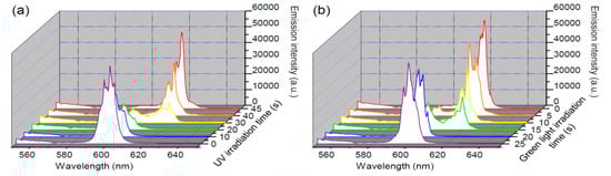
Figure 7.
Variations in the off-center pumped lasing emission of the DDNLC2-infiltrated micro tube with (a) UV light irradiation and (b) green light illumination.
The phase transition was the main reason for the wavelength change and higher intensity of the lasing emissions. In a laser, the total gain can be expressed as G(λ) = g(λ)ℓ − σ(λ)L, where ℓ is the illumination length, L is the internal circumference of the resonant path, g(λ) is the gain of the laser dye for unit length, and σ(λ) is the loss for unit length in the system []. As the total gain at 600 nm was higher than that at 620 nm when the DDNLC was in the nematic phase, the central wavelength of the lasing emission at the nematic phase was around 600 nm. On the contrary, the total gain at 620 nm exceeded that at 600 nm and thus the wavelength of the lasing emission shifted to 620 nm when the DDNLC was in the isotropic state. In addition to the shift of the lasing emission, the intensity of the lasing emission was higher at the isotropic phase compared to that at the nematic phase. Since the absorption of the laser dye and scattering from the thermal fluctuations can be significantly reduced when the DDNLC is in isotropic phase [], the emission intensity at the isotropic state was higher than the nematic state.
4. Conclusions
In this paper, a low-threshold micro laser device which can simultaneously generate random lasing at wavelength of 580 nm and 600 nm, based on a DDNLC-infiltrated micro tube, was demonstrated. These two lasing emissions could be switched by adjusting the focused spot on the micro tube. With the addition of the azo-dye, the intensity of the random lasing emission of the DDNLC-infiltrated micro tube could be controlled by irradiation of UV light and green light via the isothermal phase transitions caused by the photoisomerization of azo-dye. In addition, the wavelength of the off-center pumped lasing emission could be completely optically controlled between 600 nm and 620 nm, with the variations in the absorption (losses) and fluorescence (gain) resulting from nematic–isotropic transition. The dual method (position and completely optical control)-tunable multi-wavelength (580 nm, 600 nm, and 620 nm) leads this micro tube laser to be a highly potential candidate as a tunable micro light source.
Author Contributions
Conceptualization, J.-D.L.; methodology, P.-C.W.; data analyzation, J.-D.L., P.-C.W. and T.-S.M.; investigation, all authors; writing—original draft preparation, J.-D.L. and P.-C.W.; writing—review and editing, J.-D.L. and C.-R.L.; supervision, B.-Y.H., C.-T.K. and C.-R.L.; funding acquisition, C.-T.K. and C.-R.L. All authors have read and agreed to the published version of the manuscript.
Funding
This research was funded by the Ministry of Science and Technology (MOST) of Taiwan under Grant MOST 110-2112-M-471-001 and Grant MOST 109-2112-M-259-009-MY3.
Institutional Review Board Statement
Not applicable.
Informed Consent Statement
Not applicable.
Data Availability Statement
Not applicable.
Conflicts of Interest
The authors declare no conflict of interest.
References
- Bajoni, D.; Senellart, P.; Wertz, E.; Sagnes, I.; Miard, A.; Lemaître, A.; Bloch, J. Polariton laser using single micropillar GaAs−GaAlAs semiconductor cavities. Phys. Rev. Lett. 2008, 100, 047401. [Google Scholar] [CrossRef] [PubMed] [Green Version]
- Kuwata-Gonokami, M.; Jordan, R.H.; Dodabalapur, A.; Katz, H.E.; Schilling, M.L.; Slusher, R.E.; Ozawa, S. Polymer microdisk and microring lasers. Opt. Lett. 1995, 20, 2093–2095. [Google Scholar] [CrossRef]
- Armani, D.K.; Kippenberg, T.J.; Spillane, S.M.; Vahala, K.J. Ultra-high-Q toroid microcavity on a chip. Nature 2003, 42, 925–928. [Google Scholar] [CrossRef]
- Saito, M.; Shimatani, H.; Naruhashi, H. Tunable whispering gallery mode emission from a microdroplet in elastomer. Opt. Express 2008, 16, 11915–11919. [Google Scholar] [CrossRef]
- Saleh, B.E.A.; Teich, M.C. Fundamentals of Photonics; Wiley: New York, NY, USA, 1991; pp. 310–315. [Google Scholar]
- Wei, G.-Q.; Wang, X.-D.; Liao, L.-S. Recent advances in organic whispering-gallery mode lasers. Laser Photon. Rev. 2020, 14, 2000257. [Google Scholar]
- Coles, H.; Morris, S. Liquid-crystal lasers. Nat. Photon. 2010, 4, 676–685. [Google Scholar] [CrossRef]
- Kopp, V.I.; Fan, B.; Vithana, H.K.M.; Genack, A.Z. Low threshold lasing at the edge of a photonic stop band in cholesteric liquid crystals. Opt. Lett. 1998, 23, 1707–1709. [Google Scholar] [CrossRef] [PubMed]
- Lee, C.-R.; Lin, J.-D.; Mo, T.-S.; Horng, C.-T.; Sun, H.-Y.; Huang, S.-Y. Performance evolution of color cone lasing emissions in dye-doped cholesteric liquid crystals at different fabrication conditions. Opt. Express 2015, 23, 10168–10180. [Google Scholar] [CrossRef] [PubMed]
- Lin, J.-D.; Lin, Y.-M.; Mo, T.-S.; Lee, C.-R. Photosensitive and all-optically fast-controllable photonic bandgap device and laser in a dye-doped blue phase with a low-concentration azobenzene liquid crystal. Opt. Express 2014, 22, 9171–9181. [Google Scholar] [CrossRef] [PubMed]
- Cao, W.; Muñoz, A.; Palffy-Muhoray, P.; Taheri, B. Lasing in a three-dimensional photonic crystal of the liquid crystal blue phase II. Nat. Mater. 2002, 1, 111–113. [Google Scholar] [CrossRef]
- Chen, Z.; Hu, D.; Chen, X.; Zeng, D.; Lee, Y.; Chen, X.; Lu, J. Templated sphere phase liquid crystals for tunable random lasing. Nanomaterials 2017, 7, 392. [Google Scholar] [CrossRef] [Green Version]
- Lee, W.; Wang, W.; Lee, G.; Ryu, S.H.; Fan, X.; Yoon, D.K. Electro-tunable liquid crystal laser based on high-Q Fabry-Pérot microcavity. Opt. Express 2017, 25, 874–880. [Google Scholar] [CrossRef]
- Wang, H.-T.; Lin, J.-D.; Lee, C.-R.; Lee, W. Ultralow-threshold single-mode lasing based on a one-dimensional asymmetric photonic bandgap structure with liquid crystal as a defect layer. Opt. Lett. 2014, 39, 3516–3519. [Google Scholar] [CrossRef] [PubMed]
- Wiersma, D.S.; Cavalieri, S. Light emission: A temperature-tunable random laser. Nature 2011, 414, 708–709. [Google Scholar] [CrossRef] [PubMed]
- Ferjani, S.; De Luca, A.; Barna, V.; Versace, C.; Strangi, G. Thermo-recurrent nematic random laser. Opt. Express 2009, 17, 2042–2047. [Google Scholar] [CrossRef]
- Ye, L.; Liu, B.; Zhao, C.; Wang, Y.; Cui, Y.; Lu, Y. The electrically and magnetically controllable random laser from dye-doped liquid crystals. J. Appl. Phys. 2014, 116, 053103. [Google Scholar] [CrossRef]
- Lee, C.-R.; Lin, J.-D.; Huang, B.-Y.; Lin, S.-H.; Mo, T.-S.; Huang, S.-Y.; Kuo, C.-T.; Yeh, H.-C. Electrically controllable liquid crystal random lasers below the Fréedericksz transition threshold. Opt. Express 2011, 19, 2391–2400. [Google Scholar] [CrossRef] [PubMed]
- Lee, C.-R.; Lin, J.-D.; Huang, B.-Y.; Mo, T.-S.; Huang, S.-Y. All-optically controllable random laser based on a dye-doped liquid crystal added with a photoisomerizable dye. Opt. Express 2010, 18, 25896–25905. [Google Scholar] [CrossRef]
- Strangi, G.; Ferjani, S.; Barna, V.; De Luca, A.; Versace, C.; Scaramuzza, N.; Bartolino, R. Random lasing and weak localization of light in dye-doped nematic liquid crystals. Opt. Express 2006, 14, 7737–7744. [Google Scholar] [CrossRef]
- Ferjani, S.; Barna, V.; De Luca, A.; Versace, C.; Strangi, G. Random lasing in freely suspended dye-doped nematic liquid crystals. Opt. Lett. 2008, 33, 557–559. [Google Scholar] [CrossRef] [PubMed]
- Ferjani, S.; Barna, V.; de Luca, A.; Versace, C.; Scaramuzza, N.; Bartolino, R.; Strangi, G. Thermal behavior of random lasing in dye doped nematic liquid crystals. Appl. Phys. Lett. 2006, 89, 121109. [Google Scholar] [CrossRef]
- Moon, H.-J.; Chough, Y.-T.; An, K. Cylindrical microcavity laser based on the evanescent-wave-coupled gain. Phys. Rev. Lett. 2000, 85, 3161–3164. [Google Scholar] [CrossRef] [PubMed]
- Ye, L.; Feng, Y.; Cheng, Z.; Wang, C.; Lu, C.; Lu, Y.; Cui, Y. Coherent random lasing from dye aggregates in polydimethylsiloxane thin films. ACS Appl. Mater. Interfaces 2017, 9, 27232–27238. [Google Scholar] [CrossRef] [PubMed]
- Lin, J.-D.; Lin, H.-Y.; Wei, G.-J.; Chuang, Y.-C.; Chen, L.-J.; Mo, T.-S.; Lee, C.-R. A broadban-tunable photonic bandgap and thermally convertible laser with an ultra-low lasing threshold from a refilled chiral polymer template. J. Mater. Chem. C 2019, 7, 4740–4747. [Google Scholar] [CrossRef]
- Nagai, Y.; Fujimura, R.; Kajikawa, K. Core-resonance cylindrical whispering gallery mode laser of dye-doped nematic liquid crystal. J. Opt. Soc. Am. B 2013, 30, 2233–2239. [Google Scholar] [CrossRef]
- Lee, C.-R.; Lin, J.-D.; Huang, Y.-J.; Huang, S.-C.; Lin, S.-H.; Yu, C.-P. All-optically controllable dye-doped liquid crystal infiltrated photonic crystal fiber. Opt. Express 2011, 19, 9676–9689. [Google Scholar] [CrossRef] [PubMed]
- De Gennes, P.G.; Prost, J. The Physics of Liquid Crystals, 2nd ed.; Clarendon Press: Oxford, UK, 1993; pp. 144–148. [Google Scholar]
Publisher’s Note: MDPI stays neutral with regard to jurisdictional claims in published maps and institutional affiliations. |
© 2021 by the authors. Licensee MDPI, Basel, Switzerland. This article is an open access article distributed under the terms and conditions of the Creative Commons Attribution (CC BY) license (https://creativecommons.org/licenses/by/4.0/).