Article

Flow Analysis of Hybridized Nanomaterial Liquid Flow in the Existence of Multiple Slips and Hall Current Effect over a Slendering Stretching Surface

1
College of Mathematical Sciences, Huaibei Normal University, Huaibei 235099, China
2
Nanchang Institute of Technology, Nanchang 330044, China
3
Department of Mathematics, Quaid-I-Azam University, Islamabad 44000, Pakistan
4
Department of Mathematics, University of Gujrat, Gujrat 50700, Pakistan
5
Department of Civil Engineering, College of Engineering, Taif University, P.O. Box 11099, Taif 21944, Saudi Arabia
6
Department of Mechanical Engineering, College of Engineering, King Saud University, P.O. Box 800, Al-Riyadh 11421, Saudi Arabia
7
Mechanical Engineering Department, College of Engineering, Prince Sattam Bin Abdulaziz University, Wadi Addawaser 11991, Saudi Arabia
8
Production Engineering and Mechanical Design Department, Faculty of Engineering, Mansoura University, P.O. 35516, Mansoura 35516, Egypt
9
Department of Mathematics and Statistics, College of Science, Taif University, P.O. Box 11099, Taif 21944, Saudi Arabia
*
Author to whom correspondence should be addressed.
Crystals 2021, 11(12), 1546; https://doi.org/10.3390/cryst11121546
Submission received: 22 November 2021 / Revised: 1 December 2021 / Accepted: 8 December 2021 / Published: 10 December 2021
(This article belongs to the Special Issue Recent Advances in Fluid Mechanics with Engineering Applications)

Abstract

:
Carbon nanotubes (CNTs) are favored materials in the manufacture of electrochemical devices because of their mechanical and chemical stability, good thermal and electrical conductivities, physiochemical consistency, and featherweight. With such intriguing carbon nanotubes properties in mind, the current research aims to investigate the flow of hybridized nano liquid containing MWCNTs (multi-wall carbon nanotubes) and SWCNTs (single-wall carbon nanotubes) across a slendering surface in the presence of a gyrotactic-microorganism. The temperature and solutal energy equation are modified with the impact of the modified Fourier and Fick’s law, binary chemical reaction, viscous dissipation, and joule heating. The slip conditions are imposed on the surface boundaries. The flow equations are converted into ODEs by applying similarity variables. The bvp4c approach is applied to tackle the coupled and extremely nonlinear boundary value problem. The outputs are compared with the PCM (Parametric continuation method) to ensure that the results are accurate. The influence of involved characteristics on energy distribution, velocity profiles, concentration, and microorganism field are presented graphically. It is noted that the stronger values of the wall thickness parameter and the Hartmann number produce a retardation effect; as a result, the fluid velocity declines for MWCNT and SWCNT hybrid nano liquid. Furthermore, the transport of the mass and heat rate improves with a higher amount of both the hybrid and simple nanofluids. The amount of local skin friction and the motile density of microorganisms are discussed and tabulated. Furthermore, the findings are validated by comparing them to the published literature, which is a notable feature of the present results. In this aspect, venerable stability has been accomplished.

1. Introduction

Nanoparticles have risen in importance as a result of their numerous applications in thermal transport, heat exchangers, thermal power plants, microelectronics, and microelectronic system technology. In comparison to regular liquids, such as oil, propylene glycol, ethylene glycol, and water, nanomaterials have a high thermal efficiency. The injection of nanomaterials into pure liquids (coolants) improves their thermal conduction ability. The mixture of nanoparticles and base liquid formed the nanoliquids that are 1–100 nm in size. The heat transfer characteristics of nano liquids are determined by the usage of thermo-physical properties and the volume fraction of nanoparticles. The different groups of nanomaterials are characterized based on their shapes, properties, and sizes. CNTs (carbon nanotubes) are tubes in a cylindrical form with invaluable properties, such as strong conductivity of thermal and immense energy, making them the most attractive material in a variety of fields such as optics, drug delivery, health care, prostheses, microwave amplifiers, the environment, nanotube transistors, and many other fields [1,2,3,4,5]. Lijima first invented carbon nanotubes (CNTs) in 1991. He used the Krastschmer and Huffman process for the first time to review multi-walled carbon nanotubes (MWCNTs). In addition, Donald Bethune published single-walled carbon nanotubes (SWCNTs) in 1993. In their research, Ramasubramaniam et al. [6] discovered that SWCNTs are very useful in electrical conductivity implementations. The heat transport and flow study of carbon nanotubes (CNTs) were examined by Khan et al. [7] by the usage of a homogenous model flow and slip boundary conditions over a sheet. Raju et al. [8] examined the Carreau Casson MHD nanofluid with multiple slips and the impact of cross-diffusion on a slandering sheet. Khan et al. [9] demonstrated the inspection of a 3D nanofluid flow comprising CNTs with the Cattaneo–Christov and Darcy–Forchheimer effect. Hussain et al. [10] demonstrated the flow of CNT nanomaterials liquid across an extending surface in the porous medium regime. Koriko et al. [11] introduced the MHD bioconvective thixotropic nanomaterials liquid flow across a surface with gyrotactic microorganisms and nanoparticles. Some recent studies corresponding to this study have been found in the Refs. [12,13,14].
In the engineering processes, there are more applications of a slendering surface rather than another stretching surface. The included applications are hot rolling, melt-spinning, glass-fiber manufacturing, polymer sheet extraction, petroleum production, extrusion, an electrolyte, the formulation of plastic and rubber sheets, wire drawing, and many more. Devi and Prakash [15] examined the boundary layer MHD flow with variable liquid properties across a slendering sheet. Babu and Sandeep [16] investigated non-Newtonian liquid flow against a slendering layer with slip effect and a magnetic field. In the existence of dissipation, Arrhenius activation energy, and thermal radiation, Nandi et al. [17] introduced the Williamson 3D nanomaterial liquid flow through a slendering surface. The transport of Maxwell fluid flow’s heat features with melting heat transfer and heat sources/sinks’ impact, subject to the surface of slandering, was described by Gayatri et al. [18]. Lanjwani et al. [19] introduced the 2D MHD Casson nanofluid with nanoparticles across a surface. Reddy et al. [20] examined the heat transport of augmentation in the Magnetite nanomaterial liquid flow across a sheet using the impact of dissipation and radiation. More studies related to these stretchable surfaces can be found in Refs. [21,22,23,24,25].
Joule heating has a significant impact on MHD liquid flow. Another name of Joule heating is ohmic heating, it is the method in which we convert current energy into radiation energy, which generates heat across resistive losses. The Joule heating phenomenon is also applied in electronics gadgets. Reddy et al. [26] demonstrated the influence of Brownian motion and ohmic heating in the flow of peristaltic with compliant walls. They went on to say that the existence of Joule heating might increase the energy analysis of transfer of heat in carbon-nanotube-based systems. Hayat et al. [27] investigated flow under a curved surface with Joule heating and the regime of radiation. Ghadikolaei et al. [28] examined the MHD flow of CNTs-water nanoparticles as a non-Newtonian dusty micropolar radiative nano liquid, which was affected by ohmic heating above a stretching plate. Zhang et al. [29] observed the flow of MHD with the effect of Joule heating and convective conditions across a curved sheet. Ijaz et al. [30] numerically examined the Arrhenius activation energy for the Walter-B nanoparticle model in the attendance of Joule heating past a surface. Some investigations related to heat transfer and Joule heating can be seen in the Refs. [31,32,33,34,35].
Mixed convection flow has widespread applications across a stretching sheet from the industry and engineering points of view. The convection effect becomes more affected by the existence of a gravitational force. The heat transport and flow mechanisms are impacted by both buoyancy and the stretching forces effect. Buoyancy thermal forces are generated when the temperature of the stretching surface changes, affecting the transport of the heat rate in industrial processes. Mixed convection occurs in electronic device cooling, nuclear reactors, vehicle demisters, defroster systems, solar energy systems, boilers, and flows in the ocean and atmosphere. A radiative mixed convective flow across an inclined sheet with porous material was characterized by Moradi et al. [36]. In the existence of double stratification, Ahmad et al. [37] examined the mixed convection hybrid nano liquid flow on an exponential sheet. Joshi et al. [38] demonstrated the mass and heat transport of a radiative mixed convective flow across a permeable cylinder. Abbas et al. [39] examined the mixed convective flow with the impacts of radiation and thermophoretic across a sphere. Nadeem et al. [40] numerically discussed the carbon nanotubes (CNTs) effect on the stagnant point flow with the occurrence of mixed convection and Troian slip and Thomson conditions across a Riga plate.
The current investigation mainly focuses on the combined impacts of dissipation on MHD bio-convective flow of hybrid nano liquid under a slendering surface with slip conditions and Hall current. The transport of mass and heat investigations are represented with heat generation and activation energy. The appearance of a hybrid nanofluid comprising SWCNTs and MWCNTs with refrigerant-134A as a regular fluid and gyrotactic microorganisms is a major contribution to this study. To the best of my knowledge, no one has yet studied hybrid nanofluid flows with such effects. The comparative study through graphs is described in the current investigation. The flow model is converted into coupled ODEs using the similarity transformation and also numerically worked out by employing bvp4c Matlab’s approach [40,41,42]. The properties of dissimilar parameters are graphically demonstrated.

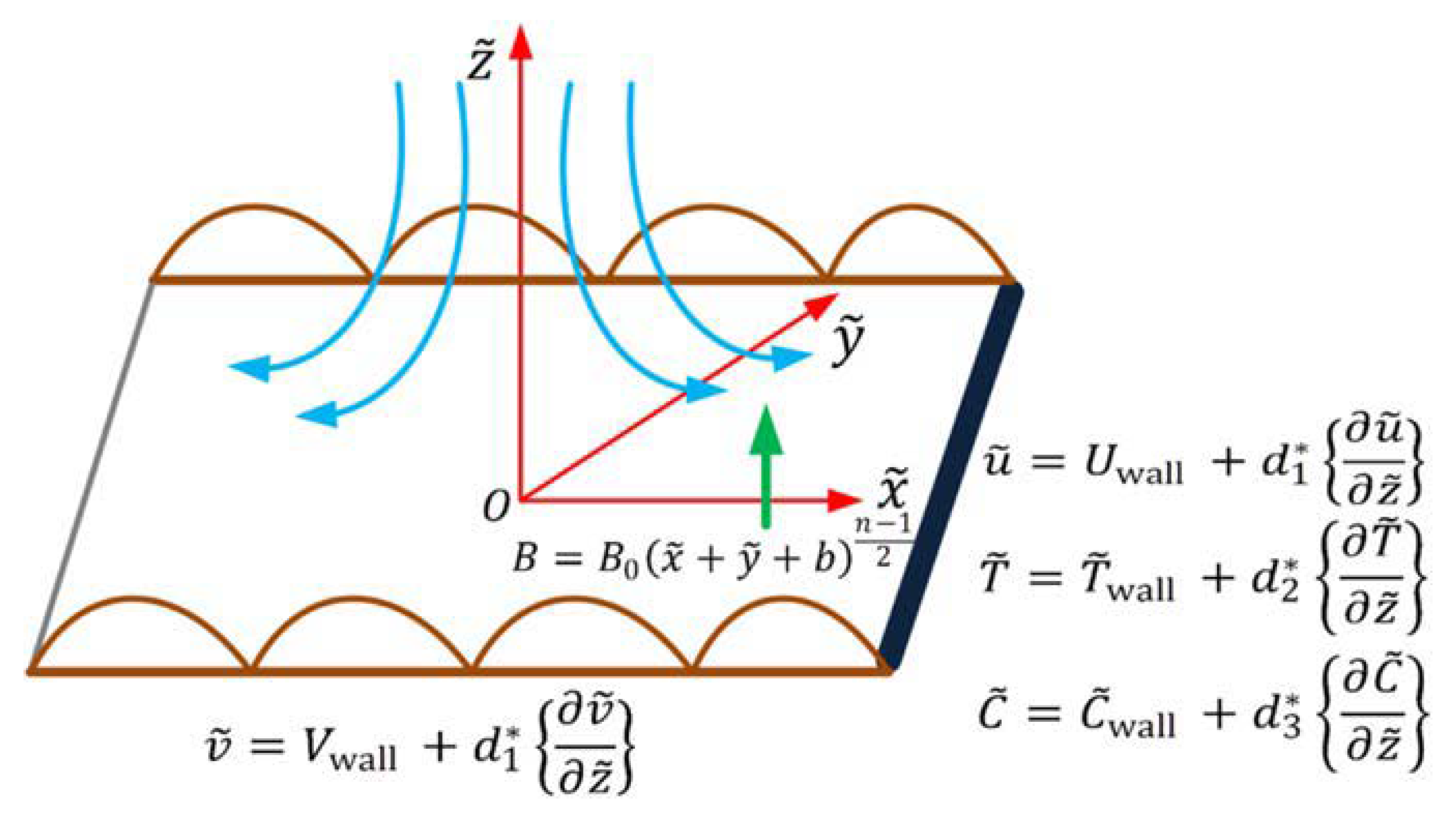
2. Mathematical Formulation

Here, we examine three-dimensional, laminar, nonlinear mixed convection MHD hybrid nano liquid flow with microorganisms over a surface. The mass and heat transport inspection was examined with the Joule heating regime. The flow diagram for the present paper is shown in Figure 1. The flow is constrained to the z 0 region. In the z-direction, a magnetic field is present. u w = u 0 x and v w = v 0 y are the stretching velocities in the x- and y- directions, respectively. The stretching sheet has a temperature T w , concentration C w , and microorganism density N w . Moreover, the ambient temperature, concentration, and microorganism density are signified by T , C , and N , respectively. The present model assumes the fluid velocity is V = u ( x , y , z ) , v ( x , y , z ) , w ( x , y , z ) . The governing equation of temperature, momentum, mass, concentration, and microorganism by using the above assumption is described as follows [20]:
v y + u x + w z = 0 ,
v u y + u u x + w u z = ν h n f 2 u z 2 + g γ 1 T T + γ 2 T T 2 + γ 3 C C + γ 4 C C 2 + γ 5 N N + γ 6 N N 2 σ h n f B 2 ρ h n f 1 + m 2 u + m v ,
u v x + v v y + w v z = ν h n f 2 v z 2 σ h n f B 2 ρ h n f 1 + m 2 v m u ,
v T y + u T x + w T z + λ e w u z T x + v u y T x + u v x T y + v v x T y + w v z T y + 2 u v 2 T x y + u 2 2 T x 2 + v 2 2 T y 2 + u w x T z + v w x T z + 2 w v 2 T y z + 2 u w 2 T x z + w 2 2 T z 2 + w w z T z + u u x T x = α h n f 2 T z 2 + σ h n f B 0 2 ρ C p h n f 1 + m 2 u 2 + v 2 + μ h n f ρ C p h n f u z 2 + v z 2 ,
u C x + v C y + w C z + λ c w u z C x + v u y C x + u v x C y + v v x C y + 2 u v 2 C x y + u 2 2 C x 2 + v 2 2 C y 2 + u w x C z + 2 w v 2 C y z + 2 u w 2 C x z + w 2 2 C z 2 + w w z C z + u u x C x + v w x C z + w v z C y = D B h n f 2 C z 2 Λ 2 C C T T n 1 exp E a k 1 T ,
u N x + v N y + w N z + b ˜ W c C w C z N C z = D N h n f 2 N z 2 .
The convenient boundary conditions are defined in the following form [17]:
  u = u w + d 1 u z , v = v w + d 1 v z , w = 0 ,   T = T w + d 2 T z , C = C w + d 3 C z , N = N w + d 4 N z .   at   z = j x + y + b 1 n 2 .
u 0 , T T , v 0 , C C ,   at   z .
In Equations (2)–(10) above, the symbols g , ν h n f , σ h n f , ρ h n f , α h n f , μ h n f , C p , γ 1 , γ 2 , γ 3 , γ 4 , γ 5 , γ 6 , D B h n f , D n h n f , W c , b ˜ , Λ , k , m , n , and E a represent the gravitational acceleration, kinematics viscosity, electrical conductivity, thermal diffusivity, dynamic viscosity, specific heat, linear and non-linear thermal expansion, linear and non-linear concentration expansion, linear and non-linear microorganism expansion, mass diffusivity, microorganism diffusivity, cell swimming speed, chemotaxis constant, chemical reaction constant, mean absorption coefficient, Hall current parameter, power–law index, and activation energy constant, respectively. Further, d 1 , d 2 , d 3 , and d 4 are the velocity slip, thermal slip, concentration slip, and microorganism slip factors, respectively. Table 1 summarizes the thermophysical characteristics of the basic liquid ( C 2 H 2 F 4 ), as well as nanoparticles such as MWCNTs and SWCNTs.

2.1. Model for Hybrid Nanomaterials Liquid and Simple Nanomaterials Liquid

Below are the reported statements for the hybrid nanomaterial liquid and the simple nanomaterial liquid (Table 2).
The subscript identifies the solid particles MWCNT ( s 1 ) and SWCNT s 2 as per the above properties.

2.2. Similarity Variables

The relevant similarity variables are given as follows [17]:
η = z u 0 ν f 1 2 y + x + b n 1 2 , u = u 0 y + x + b n F ( η ) , v = u 0 y + x + b n G ( η ) , w = u 0 ν f 1 2 y + x + b n 1 2 n + 1 2 G ( η ) + F ( η ) η 1 n 2 G ( η ) + F ( η ) , T T = T w T θ η , C C = C w ε ¯ η C ε ¯ η , N N = N w H η N H η .
The wall velocity, temperature, concentration, and microorganism density are stated as follows:
u w = u 0 y + x + b n , v 0 = v 0 y + x + b n , T w = T + T 0 y + x + b 1 n 2 , Λ 2 = K 0 2 y + x + b n 1 B = B 0 y + x + b 1 n 2 , C w C = C 0 y + x + b 1 n 2 , N w N = N 0 y + x + b 1 n 2 .
Using the above transformations, Equations (2)–(10) in a dimensionless form are as follows:
F + A 1 A 2 n + 1 2 F + G F H a A 2 σ h n f 1 + m 2 σ f F + m G + A 2 λ 1 + λ 1 θ θ + A 2 λ N r 1 + λ 2 ε ¯ ε ¯ + A 2 λ N c 1 + λ 3 H H n A 1 A 2 F + G F = 0 ,
G + A 1 A 2 n + 1 2 F + G G + H a A 2 σ h n f 1 + m 2 σ f m F G n A 1 A 2 F + G G = 0 ,
k h n f k f θ + Pr A 3 σ h n f H a E c σ f A 3 ( 1 + m 2 ) F 2 + G 2 + n + 1 2 F + G θ + Pr A 3 β n 3 2 ( F + G ) ( F + G ) θ n + 1 2 ( F + G ) 2 θ + E c Pr A 2 F 2 + G 2 = 0 ,
A 2 S c ε ¯ + n + 1 2 F + G ε ¯ + β * n 3 2 ( F + G ) ( F + G ) ε ¯ n + 1 2 ( F + G ) 2 ε ¯ K r ε ¯ 1 + δ θ n 1 exp E 1 + δ θ = 0 ,
A 2 S b H + n + 1 2 F + G H P e S b H + Ω ε ¯ + H ε ¯ = 0.
The convenient boundaries are as follows:
F = α 1 1 n 1 + n 1 + K 1 F , G = α 1 1 n 1 + n 1 + K 1 G , F = K 1 F + 1 , G = K 1 G + A , θ = K 2 θ + 1 ,   ε ¯ = 1 + K 3 ε ¯ , H = 1 + K 4 H .   at   η α 1 .
F 0 , G 0 , θ 0 , ε ¯ 0 , H 0.   at   η .
For the intervals 0 , , we described the following functions:
F ( η ) = f η α 1 = f ζ , G ( η ) = g η α 1 = g ζ , θ ( η ) = θ η α 1 = θ ζ , ε ¯ ( η ) = ε η α 1 = ε ζ , H ( η ) = h η α 1 = h ζ . .
Equations (12)–(17) take the following form by applying Equation (18):
f + A 1 A 2 n + 1 2 f + g f H a A 2 σ h n f 1 + m 2 σ f f + m g + A 2 λ 1 + λ 1 θ θ + A 2 λ N r 1 + λ 2 ε ¯ ε ¯ + A 2 λ N c 1 + λ 3 H H n A 1 A 2 f + g f = 0 ,
g + A 1 A 2 n + 1 2 f + g g + H a A 2 σ h n f 1 + m 2 σ f m f g n A 1 A 2 f + g g = 0 ,
k h n f k f θ + Pr A 3 σ h n f H a E c σ f A 3 ( 1 + m 2 ) f 2 + g 2 + n + 1 2 f + g θ + Pr A 3 β n 3 2 ( f + g ) ( f + g ) θ n + 1 2 ( f + g ) 2 θ + Pr E c A 2 f 2 + g 2 = 0 ,
A 2 S c ε + n + 1 2 f + g ε + β * n 3 2 ( f + g ) ( f + g ) ε n + 1 2 ( f + g ) 2 ε K r ε 1 + δ θ n 1 exp E 1 + δ θ = 0 ,
A 2 S b h + n + 1 2 f + g h P e S b h + Ω ε + h ε = 0.
The concerned boundary condition takes the following form:
f = α 1 1 n 1 + n 1 + K 1 f , g = α 1 1 n 1 + n 1 + K 1 g , f = 1 + K 1 f , g = A + K 1 g , θ = 1 + K 2 θ ,   ε = 1 + K 3 ε , h = 1 + K 4 h .   at   ζ 0.
f 0 , θ 0 , g 0 , ε 0 , h 0.   at   ζ .
The emerging characteristics H a , λ 1 , λ 2 , λ 3 , N r , λ , E c , E ,   S c , S b , P e , Pr , K r , α 1 , δ , and Ω , which are characterized by the Hartmann number, nonlinear convection characteristic for temperature, nonlinear convection characteristic for concentration, nonlinear convection characteristic for a microorganism, buoyancy ratio characteristic, mixed convection characteristic, Eckert number, activation energy characteristic, Schmidt number, bio-convection Schmidt number, Peclet number, Prandtl number, chemical reaction characteristic, wall thickness characteristic, temperature ratio characteristic, and microorganism difference characteristic, respectively. Further, K 1 , K 2 , K 3 , and K 4 are velocity, thermal, concentration, and microorganism slip characteristic, respectively. The mathematical form of the characteristics is written as follows:
Pr = ν f α , δ = T w T , α 1 = j u 0 ν f , N r = G r C G r T , G r T = g γ 3 C w C y + x + b 3 ν 2 , Ω = N w N N , G r C = g γ 1 T w T y + x + b 3 ν 2 , E = E a T k 1 , K r = K 0 2 u 0 , λ = G r T Re x 2 , H a = σ f B 0 2 u 0 ρ f , P e = b ˜ W c D n , S c = ν f D B , S b = ν f D n , λ 1 = γ 2 T w T γ 1 , λ 2 = γ 4 T w T γ 3 , λ 3 = γ 6 T w T γ 5 , E c = u 0 2 C p f T w T , A 1 = ( 1 ϕ 1 ) 2.5 ( 1 ϕ 2 ) 2.5 , A 2 = ( 1 ϕ 2 ) ( 1 ϕ 1 ) + ϕ 1 ρ M W C N T ρ f + ϕ 2 ρ S W C N T ρ f A 3 = ( 1 ϕ 2 ) ( 1 ϕ 1 ) + ϕ 1 ( ρ C p ) M W C N T ( ρ C p ) f + ϕ 2 ( ρ C p ) S W C N T ( ρ C p ) f .

2.3. Physical Quantities

Physical quantities such as friction drag and microorganism numbers are very precious from the engineering perspective. These quantities are defined mathematically as follows:
C f x = τ x z u w 2 ρ f , C f y = τ y z v w 2 ρ f , Q n x = x z w D n f N w N ,
In Equation (27), τ x z , τ y z , and z w are, respectively, defined as follows:
τ x z = μ h n f u z z = j y + x + b 1 n 2 , τ x z = μ h n f v z z = j y + x + b 1 n 2 , z w = D n h n f N z z = j y + x + b 1 n 2 .
In the dimensionless form, these are, respectively, written as follows:
Re x 0.5 C f x = f ( 0 ) ( 1 ϕ 1 ) 2.5 ( 1 ϕ 2 ) 2.5 , Re y 0.5 C f y = g ( 0 ) ( 1 ϕ 1 ) 2.5 ( 1 ϕ 2 ) 2.5 , Q n x Re x 0.5 = A 1 h ( 0 ) .
Re x = x + y + b u w ν and Re y = x + y + b v w ν are the Reynolds number.

3. Graphical Results and Discussion

The bvp4c numerical technique is used to solve Equations (12)–(15) with Equation (16). For numerous developing parameters, the graphical results are achieved for microorganism velocity, concentration, and temperature field. Moreover, the result of nano-liquid S W C N T C 2 H 2 F 4 and hybrid nano-liquid S W C N T M W C N T C 2 H 2 F 4 are compared and discussed. A comparison of the newly developed problem with previously published outcomes is presented in Table 3. It is demonstrated that bigger amounts of A improved the velocity gradient ( f ( 0 ) and g ( 0 ) ). Table 4 shows a comparison of the numerical outputs of the PCM and bvp4c programs. Table 5 and Table 6 show the numerical amounts of skin friction along the y-axis and x-axis and, the microorganism number.

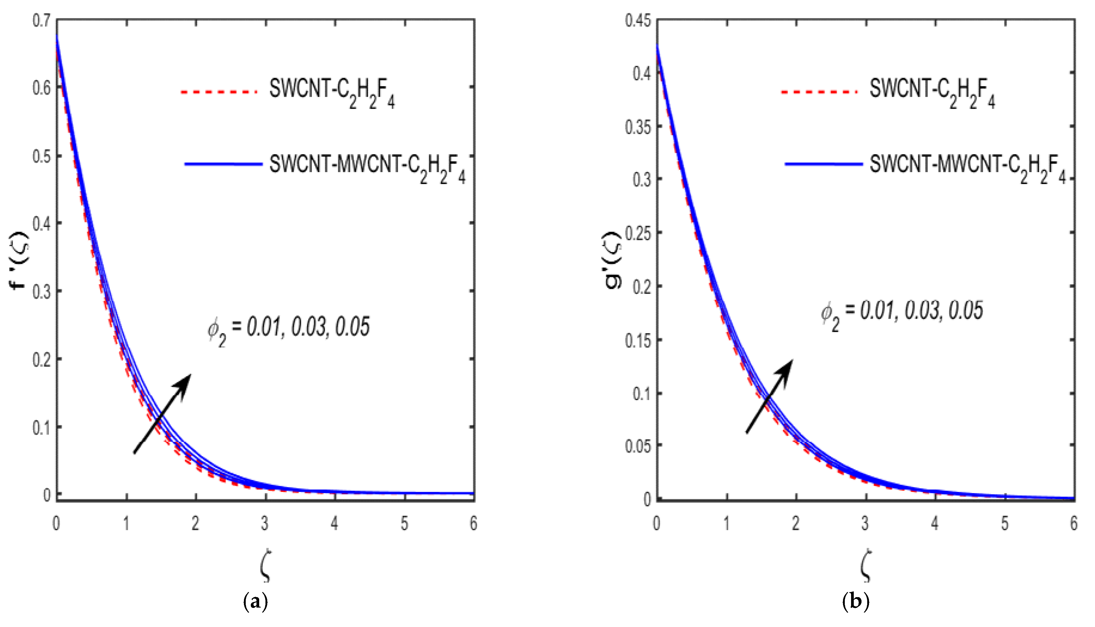
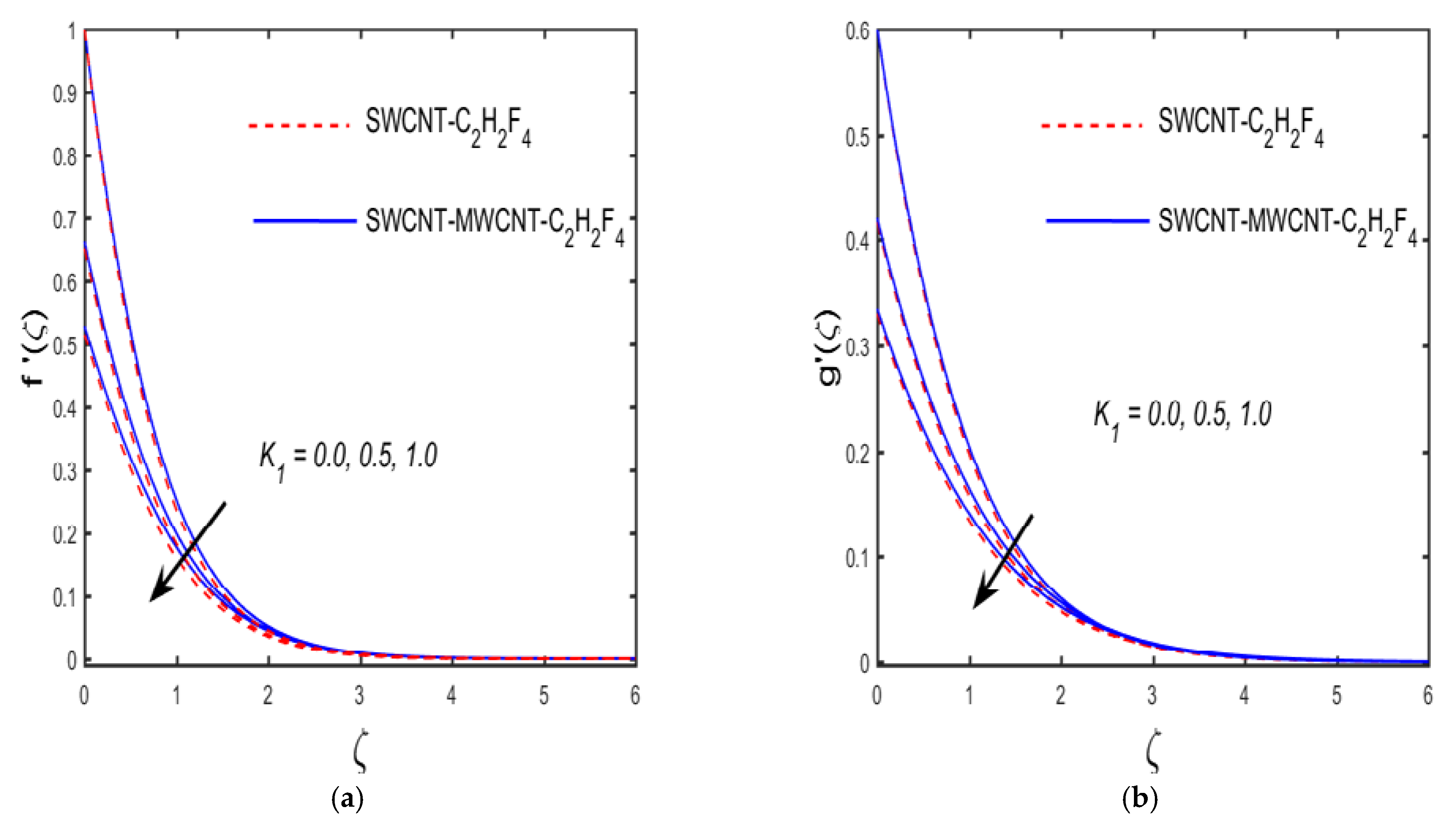
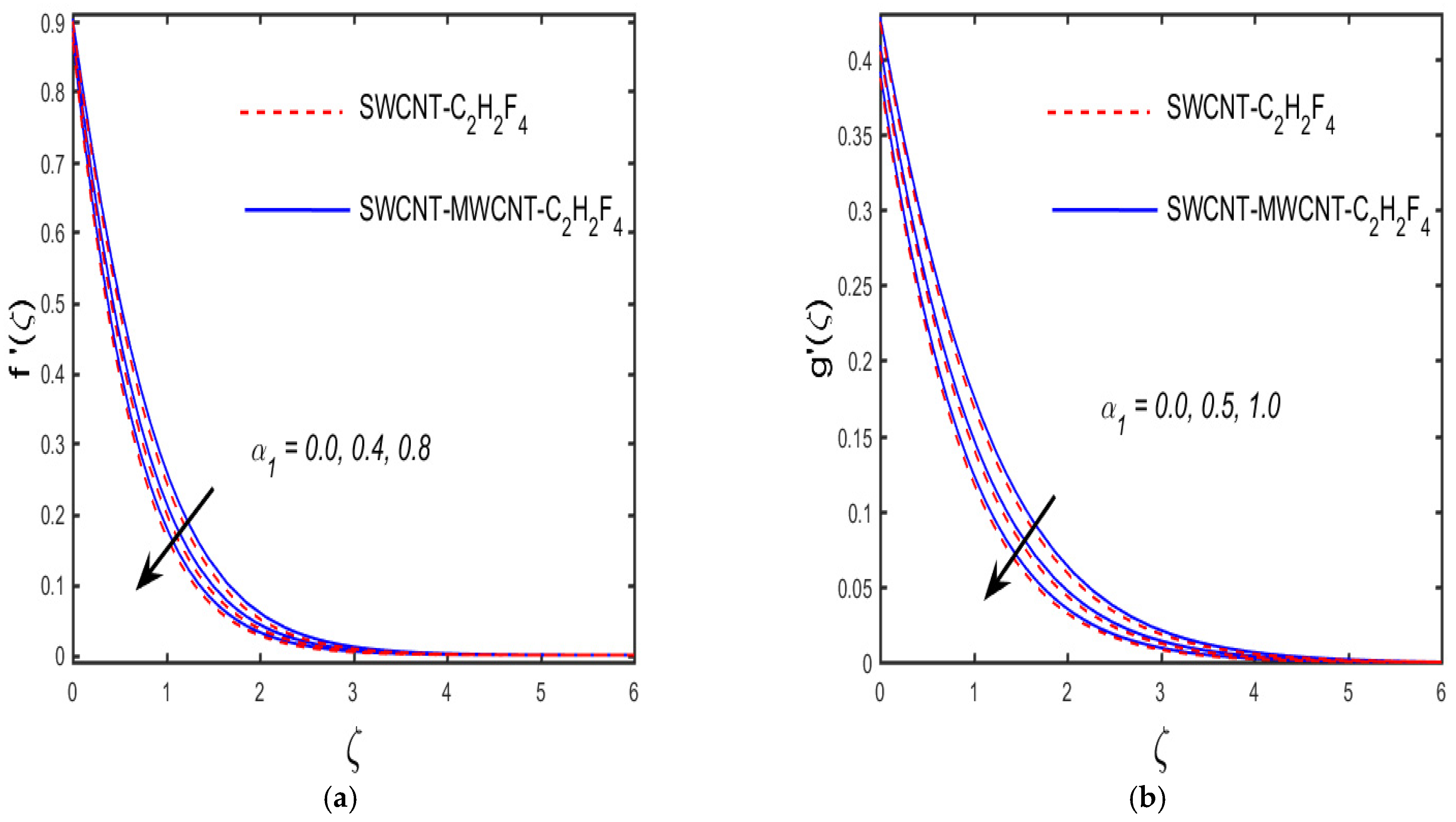
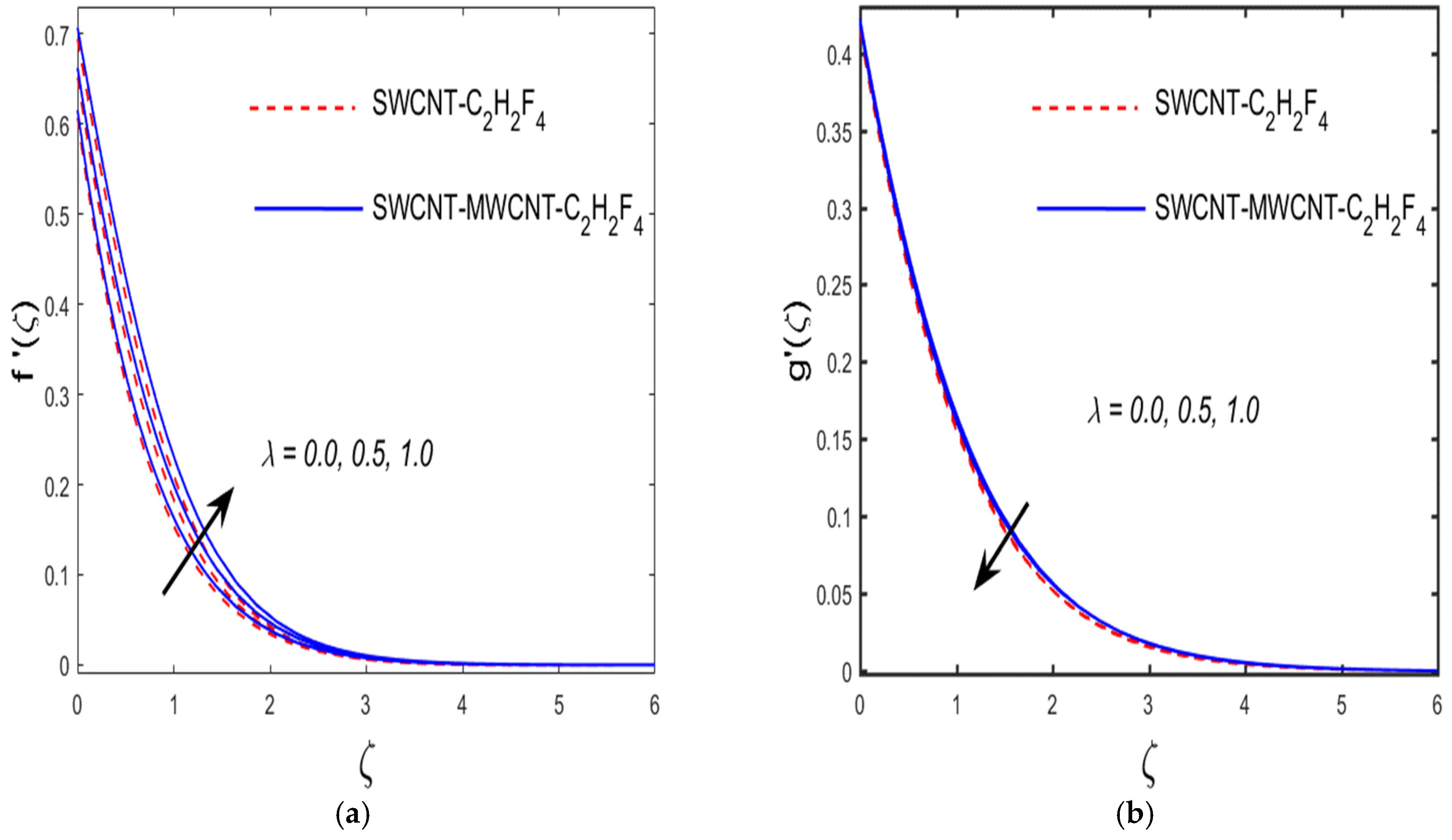
3.1. Variation of Distinct Characteristics on the Distribution of Velocity
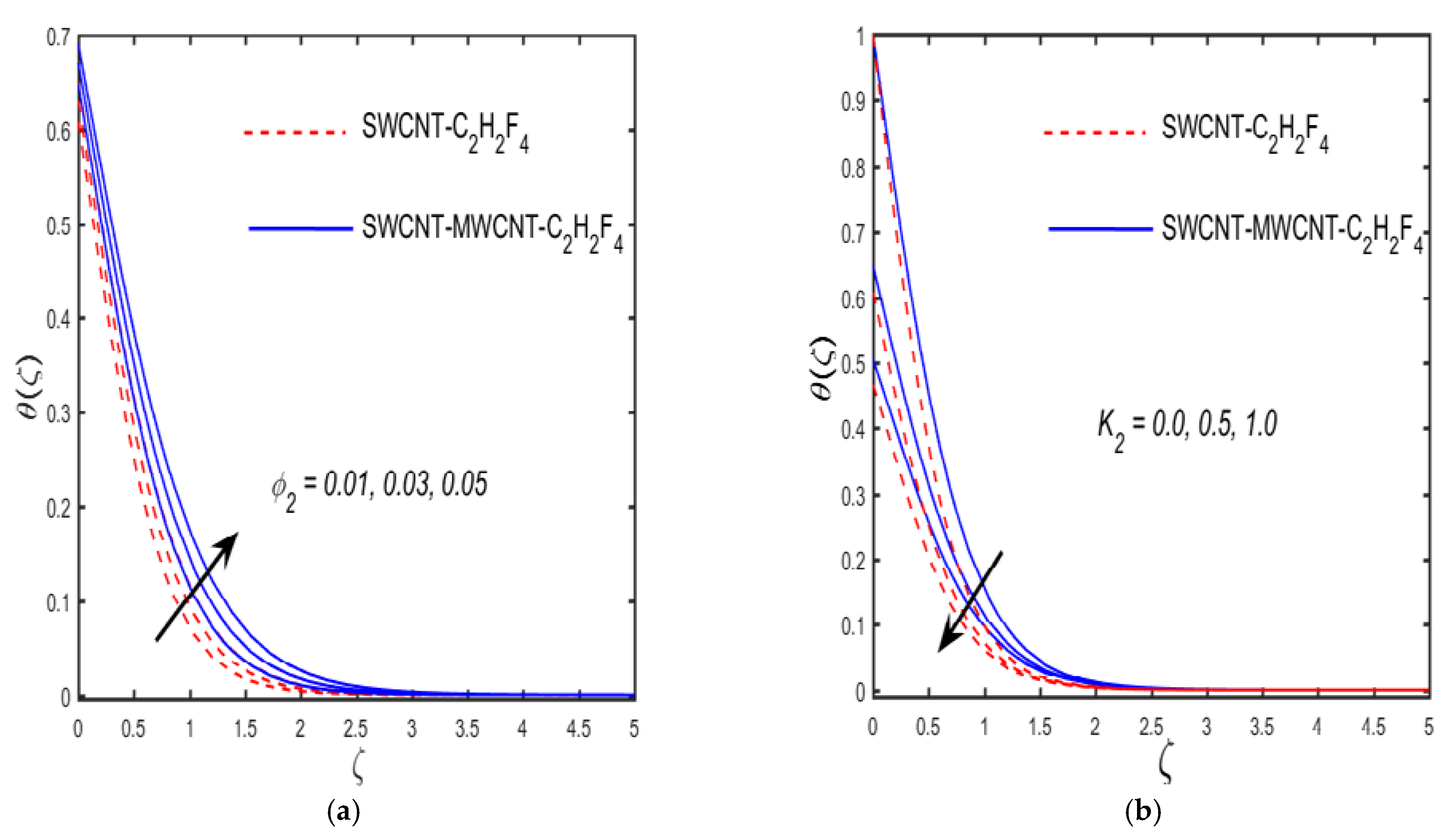
The effect of α 1 (wall thickness characteristic), H a (Hartmann number), K 1 (velocity slip characteristic), λ (mixed convection characteristic), n (power–law index characteristic), ϕ 2 (characteristic of solid volume fraction) on f ( ζ ) and g ( ζ ) is discussed in Figure 2, Figure 3, Figure 4, Figure 5, Figure 6 and Figure 7. Figure 2a,b exhibits the upshot of ϕ 2 on the velocity sketch f ( ζ ) and g ( ζ ) for both S W C N T C 2 H 2 F 4 and S W C N T M W C N T C 2 H 2 F 4 . It is clear from the figure that both f ( ζ ) and g ( ζ ) increase with the escalation ϕ 2 . The modification in f ( ζ ) and g ( ζ ) plots for various estimations of K 1 for S W C N T C 2 H 2 F 4 and S W C N T M W C N T C 2 H 2 F 4 is illustrated in Figure 3a,b. It illustrates that f ( ζ ) and g ( ζ ) are decelerated near the surface boundary while showing an opposite trend away from the surface, due to the increment of K 1 . This shows that the slip of velocity characteristics tends to improve the velocity away from the wall and a reverse trend is noted near the wall. It is considered in Figure 4a,b that by the boost of wall thickness parameter, the momentum boundary layer thickness reduces for both the hybrid and simple nanoliquids; as a result, the fluid velocity declined in both directions. It occurs because when the estimation of α 1 rises, it acts as a factor of retarding; due to this, the flow of fluid retards. The behavior in the f ( ζ ) and g ( ζ ) plots along the distinct values of H a is seen in Figure 5a,b. It discloses that the velocity of fluid in both directions ( f ( ζ ) and g ( ζ ) ) are depreciated by the enhancement of the Hartmann number for both cases. Physically, due to the appearance of the Hartmann number, the retardation effect takes place; as a result, the velocities of the liquid shrink. Figure 6a,b describe the conclusion of the combined convection parameter on the velocity field ( f ( ζ ) and g ( ζ ) ) for both cases. The figure shows that the enhancement occurred in f ( ζ ) and g ( ζ ) by the increment of λ . Physically, the liquid viscosity declines due to the enlargement of λ ; therefore, the velocities of the liquid are enlarged.

3.2. Variation in θ ( ζ ) and ε ( ζ ) Plots against Various Parameter

Figure 7, Figure 8, Figure 9, Figure 10 and Figure 11 depict the variation in temperature and concentration distribution across the various parameters for both the nanofluid and the hybrid nanofluid, such as ϕ 2 (hybrid nanofluid parameter), K 2 , K 3 (thermal and concentration slip parameter), E (activation energy parameter), K r (chemical reaction parameter), S c (Schmidt number), and H a (Hartmann number). The plots of θ ( ζ ) against the several estimations of ϕ 2 are examined in Figure 7a. It is noted that the thermal conductivity of the fluid is boosted by the inclusion of the hybrid nanofluid; this implies that the temperature of the fluid is improved by the escalation of ϕ 2 . The aspects of concentration slip and thermal characteristics on the concentration and temperature graph are intriguing in Figure 7b and Figure 8a. They explore the plots of θ ( ζ ) and ε ( ζ ) declining as the values of K 2 and K 3 improve for S W C N T C 2 H 2 F 4 and S W C N T M W C N T C 2 H 2 F 4 . Physically, by boosting the values of K 2 , the thermal diffusion rate in the flow direction decreased. Figure 8b describes the influence of H a on the field of temperature. It investigates the stronger amount of H a raising the thickness of the boundary and temperature field. The change in the ε ( ζ ) sketch against the various estimations of K r and E is represented in Figure 9a,b. It was figured out from the figure that stronger values of K r and E boost the concentration for both S W C N T C 2 H 2 F 4 and S W C N T M W C N T C 2 H 2 F 4 . Physically, due to stronger activation energy, more energy is transmitted to the fluid; due to this, the temperature of the fluid increases. Figure 10a introduces the impact of the thermal relaxation characteristic on the energy field. From Figure 10a, it is manifested that the temperature retards, with the influence of the thermal relaxation characteristic. This is because, for improving amount of thermal relaxation time, the liquid particles steadily heat transport to their surrounding particles. Figure 10b describes the result of the Schmidt number on the field of concentration. It is shown that the field of concentration decays due to the larger estimation of S c for S W C N T C 2 H 2 F 4 and S W C N T M W C N T C 2 H 2 F 4 . Physically, due to the higher values of S c , the mass diffusivity of fluid decreases and, as a result, the concentration of liquid declines.

3.3. Variation in Microorganism Profile against Various Parameters

The impacts of distinct characteristics for both the nano liquid and the hybrid nano liquid on the microorganism distribution are observed in Figure 11 and Figure 12. It is evident in Figure 11a,b that the decline shows in the microorganism density and the associated thickness of the boundary due to the larger values of P e and S b consequently for both the nano liquid and the hybrid nano liquid. Physically, stronger amounts of P e improve the cell swimming speed; as a result, microorganism density decays. Moreover, the microorganism diffusion rate shrinks due to the growth of S b , which shows that the microorganism profile is reduced. The influence of Ω and K 4 on the microorganism field is described in Figure 12a,b. It can be seen from the figure that by the enhancement of Ω and K 4 , the h ( ζ ) plot is depreciated for both the nano liquid and the hybrid nano liquid.

4. Concluding Remarks

A mathematical model of nonlinearly mixed bioconvection viscous hybridized nano liquid flow in a regime of ohmic heating and activation energy was presented. The multiple slip boundaries are imposed on the boundary of the slendering sheet. The main outcomes of this paper are illustrated as follows:
The stronger values of α 1 provided the retardation effect, which declines the liquid velocity for S W C N T C 2 H 2 F 4 and S W C N T M W C N T C 2 H 2 F 4 cases.
By escalating λ , the liquid viscosity decreases; as a result, the fluid velocity increases for S W C N T C 2 H 2 F 4 and S W C N T M W C N T C 2 H 2 F 4 .
The larger values of ϕ 2 improve the momentum and velocity boundary layer.
The temperature of the fluid increases due to the higher values of H a and n for both S W C N T C 2 H 2 F 4 and S W C N T M W C N T C 2 H 2 F 4 cases.
The concentration distribution is boosted with the enlargement of E and K r for both S W C N T C 2 H 2 F 4 and S W C N T M W C N T C 2 H 2 F 4 .
The growing values of P e and S b reduce the microorganism density for both S W C N T C 2 H 2 F 4 and S W C N T M W C N T C 2 H 2 F 4 .
By enhancing α 1 , the skin friction is the boost in the y and x directions, while the against behavior is noted for the mixed convection parameter.
The Nusselt number shows decreasing behavior for the larger estimation of E c .
The mass transfer rate improves due to the improvement of K r .
A bigger amount of the mixed convection characteristic improves the microorganism rate of transport.

Author Contributions

E.H.: Data curation, Funding acquisition, Writing—review & editing, F.W.: Formal analysis, Validation, Writing—review & editing, M.N.K.: Conceptualization, Software, Resources, S.A.: Supervision, Writing—original draft, Investigation, A.R.: Writing—review & editing, Visualization, Resources, A.H.A.: Writing—review & editing, validation, Funding acquisition, E.-S.M.S.: Methodology, Writing—review & editing, Funding acquisition, A.M.G.: Methodology, Writing—review & editing, Formal analysis, M.S.A.: Writing—review & editing, Visualization, validation. All authors have read and agreed to the published version of the manuscript.

Funding

This project was funded by Taif University Researchers Supporting Project number (TURSP-2020/252), Taif University, Taif, Saudi Arabia. This work was also supported by the University Natural Science Research Project of Anhui Province (Project nos. KJ2020B06 and KJ2020ZD008). Also this work was supported by the Researchers Supporting Project Number (RSP-2021/33), King Saud University, Riyadh, Saudi Arabia.

Data Availability Statement

All data use for this study within the article.

Acknowledgments

The authors would like to acknowledge financial support from the Taif University Researchers Supporting Project number (TURSP-2020/252), Taif University, Taif, Saudi Arabia. Additionally, this work was supported by the Researchers Supporting Project Number (RSP-2021/33), King Saud University, Riyadh, Saudi Arabia.

Conflicts of Interest

The authors declare no conflict of interest.

References

  1. Khan, U.; Ahmed, N.; Mohyud-Din, S.T. Numerical investigation for three dimensional squeezing flow of nanofluid in a rotating channel with lower stretching wall suspended by carbon nanotubes. Appl. Therm. Eng. 2017, 113, 1107–1117. [Google Scholar] [CrossRef]
  2. Hayat, T.; Haider, F.; Muhammad, T.; Alsaedi, A. On Darcy-Forchheimer flow of carbon nanotubes due to a rotating disk. Int. J. Heat Mass Transf. 2017, 112, 248–254. [Google Scholar] [CrossRef]
  3. Rahmati, A.R.; Reiszadeh, M. An experimental study on the effects of the use of multi-walled carbon nanotubes in ethylene glycol/water-based fluid with indirect heaters in gas pressure reducing stations. Appl. Therm. Eng. 2018, 134, 107–117. [Google Scholar] [CrossRef]
  4. Shahzadi, I.; Sadaf, H.; Nadeem, S.; Saleem, A. Bio-mathematical analysis for the peristaltic flow of single wall carbon nanotubes under the impact of variable viscosity and wall properties. Comput. Methods Programs Biomed. 2017, 139, 137–147. [Google Scholar] [CrossRef]
  5. Hofmann, S.; Sharma, R.; Ducati, C.; Du, G.; Mattevi, C.; Cepek, C.; Cantoro, M.; Pisana, S.; Parvez, A.; Cervantes-Sodi, F.; et al. In situ observations of catalyst dynamics during surface-bound carbon nanotube nucleation. Nano Lett. 2007, 7, 602–608. [Google Scholar] [CrossRef] [PubMed]
  6. Ramasubramaniam, R.; Chen, J.; Liu, H. Homogeneous carbon nanotube/polymer composites for electrical applications. Appl. Phys. Lett. 2003, 83, 2928–2930. [Google Scholar] [CrossRef]
  7. Khan, W.A.; Khan, Z.H.; Rahi, M. Fluid flow and heat transfer of carbon nanotubes along a flat plate with Navier slip boundary. Appl. Nanosci. 2014, 4, 633–641. [Google Scholar] [CrossRef] [Green Version]
  8. Raju, C.S.K.; Priyadarshini, P.; Ibrahim, S.M. Multiple Slip and Cross Diffusion on MHD Carreau–Cassonfluid over a Slendering Sheet with Non-uniform Heat Source/Sink. Int. J. Appl. Comput. Math. 2017, 3, 203–224. [Google Scholar] [CrossRef]
  9. Rahman, J.U.; Khan, U.; Ahmad, S.; Ramzan, M.; Suleman, M.; Lu, D.; Inam, S. Numerical simulation of Darcy–Forchheimer 3D unsteady nanofluid flow comprising carbon nanotubes with Cattaneo–Christov heat flux and velocity and thermal slip conditions. Processes 2019, 7, 687. [Google Scholar] [CrossRef] [Green Version]
  10. Hussain, Z.; Hayat, T.; Alsaedi, A.; Ahmad, B. Three-dimensional convective flow of CNTs nanofluids with heat generation/absorption effect: A numerical study. Comput. Methods Appl. Mech. Eng. 2018, 329, 40–54. [Google Scholar] [CrossRef]
  11. Koriko, O.K.; Shah, N.A.; Saleem, S.; Chung, J.D.; Omowaye, A.J.; Oreyeni, T. Exploration of bioconvection flow of MHD thixotropic nanofluid past a vertical surface coexisting with both nanoparticles and gyrotactic microorganisms. Sci. Rep. 2021, 11, 16627. [Google Scholar] [CrossRef]
  12. Khan, M.N.; Ahmad, S.; Nadeem, S. Flow and heat transfer investigation of bio–convective hybrid nanofluid with triple stratification effects. Phys. Scr. 2021, 96, 065210. [Google Scholar] [CrossRef]
  13. Zehra, I.; Abbas, N.; Amjad, M.; Nadeem, S.; Saleem, S.; Issakhov, A. Casson nanoliquid flow with Cattaneo-Christov flux analysis over a curved stretching/shrinking channel. Case Stud. Therm. Eng. 2021, 27, 101146. [Google Scholar] [CrossRef]
  14. Mathew, A.; Areekara, S.; Sabu, A.; Saleem, S. Significance of multiple slip and nanoparticle shape on stagnation point flow of silver-blood nanofluid in the presence of induced magnetic field. Surf. Interfaces 2021, 25, 101267. [Google Scholar] [CrossRef]
  15. Devi, S.A.; Prakash, M. Temperature dependent viscosity and thermal conductivity effects on hydromagnetic flow over a slendering stretching sheet. J. Niger. Math. Soc. 2015, 34, 318–330. [Google Scholar] [CrossRef] [Green Version]
  16. Babu, M.J.; Sandeep, N. MHD non-Newtonian fluid flow over a slendering stretching sheet in the presence of cross-diffusion effects. Alex. Eng. J. 2016, 55, 2193–2201. [Google Scholar] [CrossRef] [Green Version]
  17. Nandi, S.; Kumbhakar, B.; Seth, G.S.; Chamkha, A.J. Features of 3D magneto-convective nonlinear radiative Williamson nanofluid flow with activation energy, multiple slips and Hall effect. Phys. Scr. 2021, 96, 065206. [Google Scholar] [CrossRef]
  18. Gayatri, M.; Jayaramireddy, K.; Jayachandra Babu, M. Nonlinear convective flow of Maxwell fluid over a slendering stretching sheet with heat source/sink. J. Appl. Comput. Mech. 2019, 8, 60–70. [Google Scholar]
  19. Lanjwani, H.B.; Saleem, S.; Chandio, M.S.; Anwar, M.I.; Abbas, N. Stability analysis of triple solutions of Casson nanofluid past on a vertical exponentially stretching/shrinking sheet. Adv. Mech. Eng. 2021, 13. [Google Scholar] [CrossRef]
  20. Reddy, J.V.R.; Sugunamma, V.; Sandeep, N. Effect of frictional heating on radiative ferrofluid flow over a slendering stretching sheet with aligned magnetic field. Eur. Phys. J. Plus 2017, 132, 7. [Google Scholar] [CrossRef]
  21. Kumar, R.V.M.S.S.K.; Kumar, G.V.; Verma, S.V.K. Unsteady magnetohydrodynamic stagnation point flow of a nanofluid over a slendering stretching sheet using Buongiorno’s model. Int. J. Res. Ind. Eng. 2018, 7, 84–105. [Google Scholar]
  22. Alzahrani, F.; Abbas, I.A. Generalized thermoelastic interactions in a poroelastic material without energy dissipations. Int. J. Thermophys. 2020, 41, 95. [Google Scholar] [CrossRef]
  23. Alzahrani, F.; Hobiny, A.; Abbas, I.; Marin, M. An eigenvalues approach for a two-dimensional porous medium based upon weak, normal and strong thermal conductivities. Symmetry 2020, 12, 848. [Google Scholar] [CrossRef]
  24. Mabood, F.; Ashwinkumar, G.P.; Sandeep, N. Simultaneous results for unsteady flow of MHD hybrid nanoliquid above a flat/slendering surface. J. Therm. Anal. Calorim. 2021, 146, 227–239. [Google Scholar] [CrossRef]
  25. Ahmad, S.; Khan, M.N.; Nadeem, S.; Rehman, A.; Ahmad, H.; Ali, R. Impact of Joule heating and multiple slips on a Maxwell nanofluid flow past a slendering surface. Commun. Theor. Phys. 2021. [Google Scholar] [CrossRef]
  26. Reddy, M.G.; Reddy, K.V. Influence of Joule heating on MHD peristaltic flow of a nanofluid with compliant walls. Procedia Eng. 2015, 127, 1002–1009. [Google Scholar] [CrossRef] [Green Version]
  27. Hayat, T.; Khan, S.A.; Alsaedi, A.; Zia, Q.M.Z. Irreversibility analysis in Darcy-Forchheimer flow of CNTs with dissipation and Joule heating effects by a curved stretching sheet. Appl. Nanosci. 2021, 11, 187–198. [Google Scholar] [CrossRef]
  28. Ghadikolaei, S.; Hosseinzadeh, K.; Ganji, D. Numerical study on magnetohydrodynic CNTs-water nanofluids as a micropolar dusty fluid influenced by non-linear thermal radiation and Joule heating effect. Powder Technol. 2018, 340, 389–399. [Google Scholar] [CrossRef]
  29. Zhang, X.-H.; Abidi, A.; Ahmed, A.E.-S.; Khan, M.R.; El-Shorbagy, M.; Shutaywi, M.; Issakhov, A.; Galal, A.M. MHD stagnation point flow of nanofluid over a curved stretching/shrinking surface subject to the influence of Joule heating and convective condition. Case Stud. Therm. Eng. 2021, 26, 101184. [Google Scholar] [CrossRef]
  30. Ijaz, M.; Yousaf, M.; El Shafey, A.M. Arrhenius activation energy and Joule heating for Walter-B fluid with Cattaneo–Christov double-diffusion model. J. Therm. Anal. Calorim. 2021, 143, 3687–3698. [Google Scholar] [CrossRef]
  31. Abbas, I.A.; Kumar, R. Deformation due to thermal source in micropolar generalized thermoelastic half-space by finite element method. J. Comput. Theor. Nanosci. 2014, 11, 185–190. [Google Scholar] [CrossRef]
  32. Abbas, I. Eigenvalue approach on fractional order theory of thermoelastic diffusion problem for an infinite elastic medium with a spherical cavity. Appl. Math. Model. 2015, 39, 6196–6206. [Google Scholar] [CrossRef]
  33. Abbas, I.A.; Kumar, R. 2D deformation in initially stressed thermoelastic half-space with voids. Steel Compos. Struct. 2016, 20, 1103–1117. [Google Scholar] [CrossRef]
  34. Abbas, I.A.; Marin, M. Analytical solutions of a two-dimensional generalized thermoelastic diffusions problem due to laser pulse. Iran. J. Sci. Technol. Trans. Mech. Eng. 2018, 42, 57–71. [Google Scholar] [CrossRef]
  35. Xia, W.-F.; Hafeez, M.U.; Khan, M.I.; Shah, N.A.; Chung, J.D. Entropy optimized dissipative flow of hybrid nanofluid in the presence of non-linear thermal radiation and Joule heating. Sci. Rep. 2021, 11, 16067. [Google Scholar] [CrossRef]
  36. Moradi, A.; Ahmadikia, H.; Hayat, T.; Alsaedi, A. On mixed convection–radiation interaction about an inclined plate through a porous medium. Int. J. Therm. Sci. 2013, 64, 129–136. [Google Scholar] [CrossRef]
  37. Ahmad, S.; Nadeem, S.; Khan, M.N. Mixed convection hybridized micropolar nanofluid with triple stratification and Cattaneo–Christov heat flux model. Phys. Scr. 2021, 96, 075205. [Google Scholar] [CrossRef]
  38. Joshi, N.; Bisht, V.; Bhakuni, A.S.; Pathak, G. Effect of mass transfer and radiation on mixed convection boundary layer flow over a permeable vertical cylinder with surface heat flux and mass flux. Int. J. Comput. Methods Eng. Sci. Mech. 2021, 22, 216–224. [Google Scholar] [CrossRef]
  39. Abbas, A.; Ashraf, M.; Chamkha, A.J. Combined effects of thermal radiation and thermophoretic motion on mixed convection boundary layer flow. Alex. Eng. J. 2021, 60, 3243–3252. [Google Scholar] [CrossRef]
  40. Nadeem, S.; Ahmad, S.; Khan, M.N. Mixed convection flow of hybrid nanoparticle along a Riga surface with Thomson and Troian slip condition. J. Therm. Anal. Calorim. 2021, 143, 2099–2109. [Google Scholar] [CrossRef]
  41. Khan, J.A.; Mustafa, M.; Hayat, T.; Alsaedi, A. On three-dimensional flow and heat transfer over a non-linearly stretching sheet: Analytical and numerical solutions. PLoS ONE 2014, 9, e107287. [Google Scholar] [CrossRef]
  42. Hussain, F.; Saleem, S.; Nazeer, M.; Al-Mubaddel, F.S.; Ali, A.; Saleem, A.; Saleem, M. Mathematical modeling and numerical solution of cross-flow of non-Newtonian fluid: Effects of viscous dissipation and slip boundary conditions. ZAMM-J. Appl. Math. Mech. Z. Angew. Math. Mech. 2021, e202100130. [Google Scholar] [CrossRef]
Figure 1. Physical sketch of the problem.
Crystals 11 01546 g001
Figure 2. (a,b) Upshot in f ( ζ ) and g ( ζ ) for ϕ 2 .
Crystals 11 01546 g002
Figure 3. (a,b) Upshot in f ( ζ ) and g ( ζ ) for K 1 .
Crystals 11 01546 g003
Figure 4. (a,b) Upshot in f ( ζ ) and g ( ζ ) for α 1 .
Crystals 11 01546 g004
Figure 5. (a,b) Upshot in f ( ζ ) and g ( ζ ) for H a .
Crystals 11 01546 g005
Figure 6. (a,b) Upshot in f ( ζ ) and g ( ζ ) for λ .
Crystals 11 01546 g006
Figure 7. (a,b) Upshot in θ ( ζ ) for ϕ 2 and ε ( ζ ) for K 2 .
Crystals 11 01546 g007
Figure 8. (a,b) Upshot in ε ( ζ ) for K 3 and θ ( ζ ) for H a .
Crystals 11 01546 g008
Figure 9. (a,b) Upshot in ε ( ζ ) for K r and E .
Crystals 11 01546 g009
Figure 10. (a,b) Upshot in ε ( ζ ) for E and K r .
Crystals 11 01546 g010
Figure 11. (a,b) Upshot in h ( ζ ) for P e and S b .
Crystals 11 01546 g011
Figure 12. (a,b) Upshot in h ( ζ ) for Ω and K 4 .
Crystals 11 01546 g012
Table 1. Thermophysical properties of the base fluid and the nanoparticles.
Physical PropertiesNanoparticlesBASE FLUID
SWCNTsMWCNTs C 2 H 2 F 4
ρ (kg/m3)260016001199.7
C p (J/kg K)4257961432
k (W/mK)660030000.0803
Table 2. The hybrid nanomaterial liquid and the simple nanomaterial liquid report.
Properties S W C N T C 2 H 2 F 4
Viscosity   ( μ ) μ n f = μ f ( 1 ϕ ) 2.5
Density   ( ρ ) ρ n f = ϕ ρ S W C N T + ( 1 ϕ ) ρ C 2 H 2 F 4 ,
Conductivity   ( k ) k n f k f = ( n 1 ) k C 2 H 2 F 4 + k S W C N T ( n 1 ) ϕ ( k C 2 H 2 F 4 k S W C N T ) ( n 1 ) k C 2 H 2 F 4 + k S W C N T + ϕ ( k C 2 H 2 F 4 k S W C N T ) ,
Heat capacity   ( ρ C p ) ( ρ C p ) n f = ( ρ C p ) S W C N T ϕ + ( ρ C p ) C 2 H 2 F 4 ( 1 ϕ )
Properties S W C N T M W C N T C 2 H 2 F 4
Viscosity   ( μ ) μ h n f = μ f ( 1 ϕ 1 ) 25 / 10 ( 1 ϕ 2 ) 25 / 10 ,
Heat capacity   ( ρ C p ) ( ρ C p ) h n f = ( ρ C p ) s 2 ϕ 2 ( ϕ 2 1 ) ϕ 1 ( ρ C p ) s 1 + ( 1 ϕ 1 ) ( ρ C p ) f ,
Density   ( ρ )   ρ h n f = ϕ 1 ( 1 ϕ 2 ) ρ s 1 + ( 1 ϕ 1 ) ( 1 ϕ 2 ) ρ f + ρ s 2 ϕ 2 ,
Thermal conductivity   ( k )   k h n f k b f = ( 1 ϕ 2 ) + 2 ϕ 2 ( k S W C N T k S W C N T k b f ) ln ( k S W C N T + k b f k b f ) ( 1 ϕ 2 ) + 2 ϕ 2 ( k b f k S W C N T k b f ) ln ( k S W C N T + k b f k b f ) ,   k b f k f = ( 1 ϕ 1 ) + 2 ϕ 1 ( k M W C N T k M W C N T k f ) ln ( k M W C N T + k f k f ) ( 1 ϕ 1 ) + 2 ϕ 1 ( k f k M W C N T k f ) ln ( k M W C N T + k f k f ) .
Table 3. Evaluation of f ( 0 ) and g ( 0 ) with past data, when H a = α 1 = 0 = K 1 = K 2 = ϕ 1 , 2 .
Nandi et al. [17]Khan et al. [41]Presents Results
n A f ( 0 ) g ( 0 ) f ( 0 ) g ( 0 ) f ( 0 ) g ( 0 )
1.00.0−1.0000070.00000−1.0000000.00000−1.0000080.00000
1.00.5−1.22476−0.612373−1.224745−0.612372−1.22478−0.612374
1.01.0−1.414422−0.414212−1.414214−0.414214−1.414424−0.414215
3.00.0−1.6243570.00000−1.6243560.00000−1.6243550.000000
3.00.5−1.989423−0.994711−1.989422−0.994711−1.989425−0.994713
3.01.0−2.297188−2.297188−2.297186−2.297186−2.2297186−2.297186
Table 4. Comparison between PCM and bvp4c method.
ζ PCMBvp4cAbsolute Error
1.01.000001.000004.06320 × 10−12
1.21.177831.177833.387721 × 10−8
1.40.977450.977453.845461 × 10−8
1.60.897180.897183.813381 × 10−8
1.80.533990.533992.287861 × 10−8
Table 5. Numerical values of C f x Re x 0.5 and C f y Re y 0.5 against the various parameters.
α 1   ϕ 2   K 1 n λ C f x Re x 0.5 C f y Re y 0.5
Simple NanofluidHybrid NanofluidSimple NanofluidHybrid Nanofluid
0.20.010.50.30.50.494830.529830.362060.38382
0.3 0.538220.570760.372070.39411
0.4 0.576380.607630.381580.40399
0.02 0.504900.540410.368440.39046
0.03 0.515140.551170.375000.39730
0.05 0.525570.562130.381740.40433
0.1 0.743570.783670.556140.57702
1.5 0.206190.236580.157130.19916
3.0 0.104750.135720.093620.11968
0.1 0.381250.403350.276020.30811
0.5 0.473420.501390.331290.36567
0.7 0.502410.534950.351560.38125
0.10.701230.731270.332450.36431
0.30.635230.651250.317220.35543
0.50.513450.529170.301250.33175
Table 6. Variation in Re x 1 / 2 N n x for distinct characteristics.
ϕ 2   N c N r S b K 4 Re x - 1 / 2 Q n x
Simple NanofluidHybrid Nanofluid
0.020.10.10.10.11.098601.23250
0.03 1.142311.28112
0.04 1.188011.33190
0.3 1.104921.24482
0.4 1.104331.24425
0.5 1.103751.24374
0.2 1.184541.33462
0.3 1.184031.33401
0.4 1.183621.33365
0.2 1.165211.28521
0.3 1.189631.30961
0.4 1.203621.32361
1.01.153581.33358
1.51.106801.26680
2.01.050451.20002
Publisher’s Note: MDPI stays neutral with regard to jurisdictional claims in published maps and institutional affiliations.

