Article

Impact Response of Preplaced Aggregate Fibrous Concrete Hammerhead Pier Beam Designed with Topology Optimization

by
Meivazhisalai Parasuraman Salaimanimagudam
1,
Gunasekaran Murali
1,*,
C. M. Vivek Vardhan
2,
Mugahed Amran
3,4,
Nikolai Vatin
5,
Roman Fediuk
6 and
Yuriy Vasilev
7
1
School of Civil Engineering, SASTRA Deemed to be University, Thanjavur 613401, India
2
Department of Civil Engineering, Malla Reddy Engineering College (Autonomous), Maisammaguda, Hyderabad 500015, India
3
Department of Civil Engineering, College of Engineering, Prince Sattam Bin Abdulaziz University, Alkharj 16273, Saudi Arabia
4
Department of Civil Engineering, Faculty of Engineering, Amran University and IT, Quhal, Amran Province 9677, Yemen
5
Institute of Civil Engineering, Peter the Great St. Petersburg Polytechnic University, 195251 St. Petersburg, Russia
6
Polytechnic Institute, Far Eastern Federal University, 690922 Vladivostok, Russia
7
Department of Road-Building Materials, Moscow Automobile and Road Construction University, 125319 Moscow, Russia
*
Author to whom correspondence should be addressed.
Crystals 2021, 11(2), 147; https://doi.org/10.3390/cryst11020147
Submission received: 14 December 2020 / Revised: 15 January 2021 / Accepted: 28 January 2021 / Published: 31 January 2021

Abstract

:
This research aimed to study the impact response of topology optimized hammerhead pier beam (HPB) based on the density approach. The HPB is prepared with the concept of preplaced aggregate fibrous concrete (PAFC) comprising two primary approaches; first, the coarse aggregate and fiber are prepacked into the designed formwork. Second, the gaps between the aggregate and fiber are filled with cement grout. In this work, an attempt has been made to study an impact response of HPB made with PAFC. Five HPBs were prepared and strengthened with steel fibers with two different schemes, Firstly, the HPB was reinforced with a full cross-section at 2 and 4% of steel fiber, while another set of beams were only reinforced in the tension zone with the same amount of fibers. The study parameters included compressive strength, impact strength, impact ductility index, number of main and secondary cracks, and failure pattern. It was observed that the PAFC had an increase in compressive strength up to 56.9%, compared with nonfibred concrete. A fully fibered concrete beam with 4% fiber addition was the best at taking impact, and the initial crack and failures were observed at 2725.1 J and 3009.8 J, respectively, compared with non-fibered and tension zone fibered concrete beams. Compressive local damage and transverse flexural cracks were observed, which had caused initial cracks and final failure. The HPB with a full reinforced scheme at 4% dosage exhibited higher impact strength than the normal concrete and beam reinforced only in the tension zone.

1. Introduction

The construction industry is moving towards automation. Concrete 3D printing plays a vital role in modern construction, and the progress of this field was summarized by Bhattacherjee et al. [1]. Additives being manufactured for concrete reduces the manufacturing constraints for topology optimized structures. The major problem in topology optimization is to create the right formwork for concrete, traditional formworks need much post-processing, which affects the optimality of the structures. Complex formworks have been achieved by using fabric formworks in the past decades [2]. Topology optimization reduces the constraints that are encountered post-processing. Structural optimizations are commonly used in various industries such as automobile, aerospace, etc. [3,4,5,6]. Concrete 3D printing is oriented towards the utilization of topology optimization techniques in civil engineering [7,8,9]. The regulations and codes for concrete 3D printing need to be developed further to ensure safety and structural integrity. The orientations of fiber in concrete during 3D printing and its structural optimization aspects are discussed by Schmidt and Kabir et al. [10,11].
From the aesthetic perspective, the topology optimization is recommended by the community of architects and engineers [12,13,14]. According to Montes et al. [15], topology optimization’s main perceptions reduce structural cost and improve the structures’ functionality. There are different types of optimization algorithms, such as solid isotropic material penalization (SIMP) [16,17,18], method of level set [19,20,21], and the method of phase-field [22]. For topology optimization, the method of SIMP is utilized to overcome the given constraints. In general, the topology optimized structures are examined by numerical simulations only [23,24,25,26].
This paper is aimed to study the impact response of topology optimized hammerhead pier beam (HPB) based on the density approach, to improve it’s functionality. The manufacturing constraints are reduced when preplaced aggregate concrete (PAC) is used compared to the traditional casting method. The PAC can hold a high amount of fibers and aggregates, making it different compared to the traditional casting process. First, aggregate and fiber were filled in the formwork and then specially prepared grout was poured over it, which fills the voids between them [27,28]. Topology optimized structure may have some complicated shapes, challenging to cast using normal concreting as it may cause honeycombing and segregation and consume massive human resources. PAC handles the complicated shapes without heavy energy consumption during casting, and also stiffness of concrete is comparatively increased. In the past decades, PAC usage has increased in prefabrication construction industries, rehabilitation works, and massive concrete structures [29,30,31]. Jing studied the environmental friendly behavior of PAC with low cement consumption [32]. The thermal and mechanical properties of PAC were discussed by Stempkowska et al. [33]. When an external load is applied over PAC, the stress is well distributed along the preplaced aggregate contact area and increases its elastic modulus. A nondestructive test for determining the fluidity of grout was proposed by Jinyoung et al. [34].
The blast and impact response of structural elements and different types of piers and beams of the bridge were discussed by several researchers [35,36,37]. Similarly, the numerical investigation of topology optimized structures was carried out by several researchers [38,39,40]. Unfortunately, few studies have reported the impact of topology-optimized structures [23] with fibrous concrete. In this perspective, this study aims to investigate the impact of the behaviour of topology optimized HHB made with PAC.
A finite element analysis (FEA) controlled framework was used in this work, which is more efficient while comparing with traditional optimization engines [41]. In the traditional framework, the topology optimization engine required FEA, but FEA requires topology optimization in an FEA-based engine. The comparison of those two frameworks is illustrated in Figure 1. FEA-based engine pre-calculates the required data for the optimization; hence the repetitive process is avoided, which speeds up the process.
An FEA-based frameworks optimization engine decides to solve the problem either using the optimality criteria method (OCM) or moving method asymptotes (MMA) depending upon the number of constraints. The engine’s main objective, to get minimum compliance in the number of iterations is illustrated in Figure 2. The aim is to determine the optimal solution with less compliance without constraints infringement. The OCM quickly and effectively handles the single constraints optimization problem, which scales up and works fast while compared with MMA. In OCM the required information for the optimization engine is pre-stored. Hence there is no need to depend on the information from past iterations.
Therefore, the main objective of this study is to study the impact resistance of topology optimized Hammerhead Pier Beam (HPB) based on the density approach and to also optimize the shape of the beam using the density-based technique to reduce the structure’s weight without compromising strength and durability. However, this research has been carried out in two stages; first, the topology optimization of HPB was performed based on the density-based technique [41]. Second, the topology optimized HPB was tested against the impact load.

2. Materials and Methods
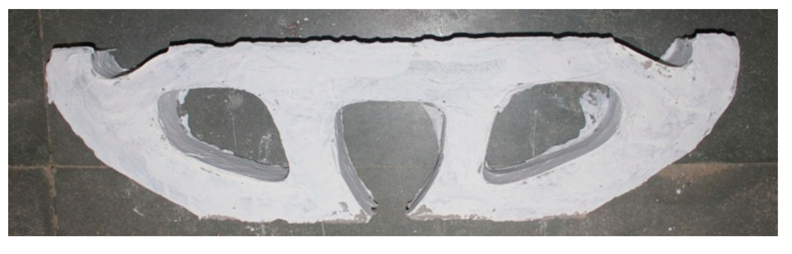
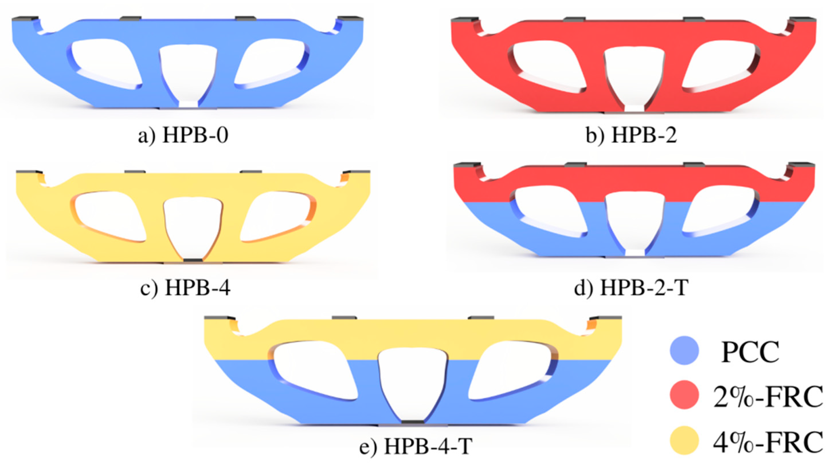
Moving method asymptotes smoothly handles multiple constraints simultaneously. MMA requires some space for storing information from previous iterations and is influential in solving compliance and volume fractions objective problems effortlessly. The internal parameters of MMA need to be tuned for quick convergence with stability. In this research work, the optimization engine needed to handle several constraints, such as design constraints and manufacturing constraints, as shown in Figure 3. In design, constraints define information regarding volume fraction and stress. Depending upon the manufacturing methods, constraints are chosen. In this case, the preplaced aggregate fibrous Concrete (PAFC) method was used, and hence extrudes constraint was considered. The minimum thickness of the optimized structural elements was also taken into account to avoid nondesignable characteristic creation of the optimized element and ensure stress distribution without any stress concentration. The orange arrow in Figure 2 and Figure 3 indicate the gradient of the slope. The iteration will stop only when the curve’s gradient becomes zero or minimum without infringement of constraints. The foremost intention of topology optimization in structure is to determine the structure’s optimum shape within the given constraints. A field of design domain is illustrated in Figure 4, where the rectangular HPB design domain is highlighted in blue color, with the H × L × W dimensions.

2.1. The Specimen

The limitations of experimental testing and the specimen’s complex shape for casting lead to a scale down of the specimen to 1:20. Table 1 demonstrates the details of the scaled-down specimens, such as height H = 230 mm, length L = 910 mm, and width W = 76 mm. The four-point load of 2.2 kN, each applied at a distance of L/3 between the loads and the support, was provided. Figure 4 illustrates the precise location of four loading points and support conditions. The loads versus displacement results for all tested beams were explained in our earlier study [41].
The optimal solution depends upon the given constraints, even though the manufacturing constraints made casting relatively more comfortable, and the post-processing was carried out minimally [41]. The post-processing was reduced using three-dimensional data while two-dimensional data outputs were commonly used [7,8,15,26]. Figure 5 is the optimal solution for the given design domain with combinations of load cases and boundary conditions.

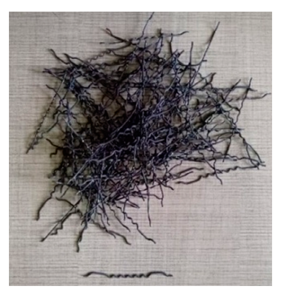
2.2. Cementitious Materials

A cementitious material categorized as portland pozzolana cement was utilized as per IS:1489-1991 [42]. The fine aggregates used were river rand of 4.75 mm maximum size, which had a density, specific gravity, and fineness modulus of 2650 kg/m3, 3.14, and 2.6, respectively, in accordance with IS:383-2016 [43]. The used coarse aggregates were well-graded with a size between 10 to 12.5 mm, water absorption of 0.56%, and a specific gravity of 2.69. A superplasticizer of brand Tech mix 640, available in the local market was used to reduce the water, flowable grout and to meet the efflux time. The dosage of superplasticizer was ranged from 0.3 to 0.5% by weight of cement. A steel fiber (hybrid hooked end – crimped) was used to reinforce the HPB, and its appearance is depicted in Figure 6 and the fiber property is discussed in Table 2.

2.3. Mixture Composition

In this research work, five diverse topology optimized hammerhead pier beams (TOHPBs) were designed for the determination of the optimum utilization of fibers in the concrete, in order to optimize the shape of the designed beams using the density-based technique to reduce the structure’s weight without compromising strength and durability. The fiber dosage was controlled depending on the compression and tension zone of TOHPB. The tension and compression zones where predicted in Altair inspire is illustrated in Figure 7, which shows that the top chord of TOHPB was a tension member, and the bottom chord acted as a compression member. The TOHPB was divided into two parts, namely the tension member with the volume of   V T and compression member with the volume of V c . The first TOHPB is designed as a reference beam with non-fibrous concrete, and hence the volume of steel fiber V S is equal to zero and is named as HPB-0. The volume of steel fiber were V S = 2 %   ( V c +     V T ) and 4 %   ( V c +     V T ) in HPB-2 and HPB-4, respectively. In the case of HPB-2-T and HPB-4-T, the volume of the steel fiber V S was equal to 2 %   V T and 4 %   V T respectively. The ratio of water to binder (w/b) is 0.42 and sand to binder (s/b) is 1.0 were used to get optimum efflux time (t), which avoided honeycombing. A superplasticizer was used to produce flowable grout in the aggregate and fiber skeleton. To achieve an optimized W/B and S/B ratio, a series of preliminary tests were employed to achieve an efflux time of 35–40 ± 2 s as per ASTM C939 [44]. The dosage of superplasticizer is generally restricted to 1% by cement weight [42]. In this investigation, the dosages of superplasticizer were selected from 0.3% to 0.5% for fibrous and nonfibrous concrete. The mixture composition, dosages of fiber, and scheme of reinforcement used in the present investigation are demonstrated in Table 3. Figure 8 illustrates a scheme of reinforcement and dosage of fiber used in TOHPB for a clearer view.

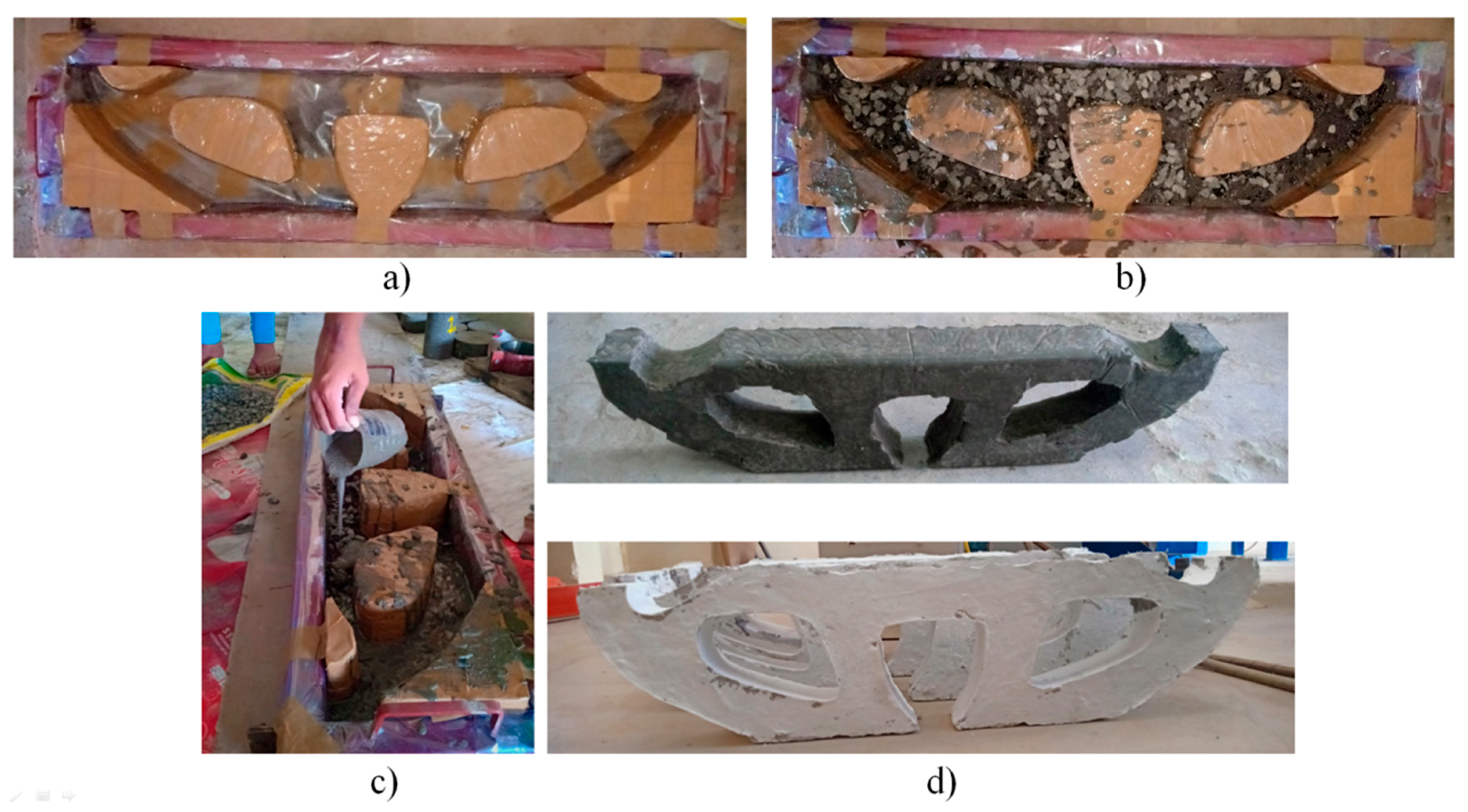
2.4. Process of TOHPB Preparation
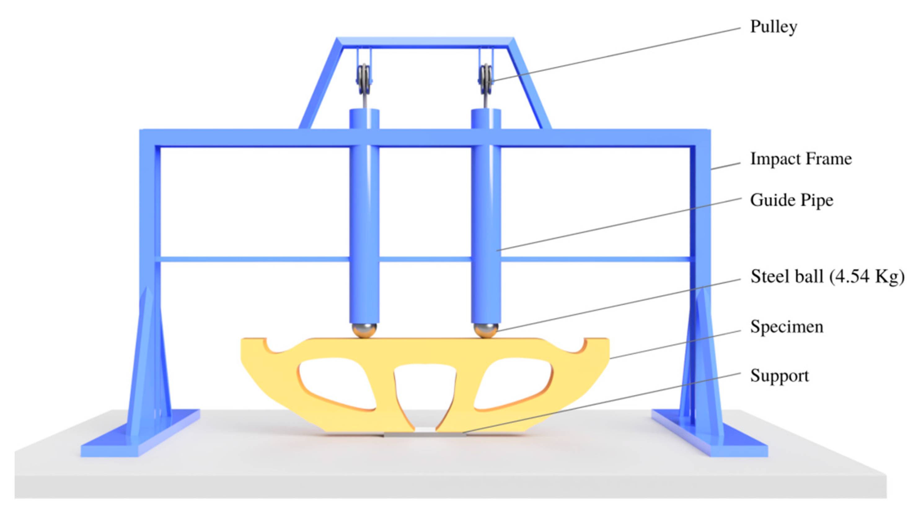
First, the 910 × 230 × 76 mm3 rectangular steel framework was prepared and kept ready for the casting process. Solid wooden blocks were cut according to the shape of the TOHPB and then placed into the empty framework to obtain the shape of HPB. The coarse aggregates were pre-soaked before casting to avoid more water absorption and to alleviates the grouts’ ultimate ratio of W/B. Figure 9 illustrates the casting process of HPB comprising two primary approaches; first, the coarse aggregate and fiber were prepacked into the designed formwork. Second, the gaps between the aggregate and fiber were filled with cement grout. The casting process was completed in two-layer. A light vibration was applied to prevent honeycombing and ensuring high compactness. Furthermore, cubes of 100 mm were cast to assess the compression strength of nonfibrous and fibrous concrete.

2.5. Test Setup

According to the ACI committee, 544 [45], a repeated impact test was carried using two numbers of steel balls with a weight of 4.54 kg. The steel ball was dropped freely using a pulley from a height of 457 mm inside a guide pipe to ensure the replicated impacts, which targeted the upper side of the specimen with one-third of the span from both ends as indicated in Figure 10. The specimen was supported over a steel plate with the L/6 of the beam span. The repeated impacts were counted, and the initial crack (IC) was noted for further studies. Impacts were repeated up to failure (FA) occurrence. The naked eye could visualize the initial crack propagation and final failure occurrence. The impact energy was calculated using Equation (1)
I m p a c t   e n e r g y   ( J ) =   N   × ( m   g   h )
where variable N denotes the number of repeated impacts, m is the mass of the steel ball (4.54 Kg), g is the acceleration due to gravity 9.81 m/s, and h is the free-fall drop height 457 mm

3. Results and Discussion

3.1. Compressive Strength of PAFC

The observed compressive strength of PAFC specimens by incorporating 2 and 4% dosage of fibers at the age of 28 days is illustrated in Figure 11. The results indicated an increasing trend in compressive strength with increasing the fiber dosage from 2 to 4%. It can be noted prudently from Figure 11 that an increased compressive strength was observed in specimens comprising 2 and 4% of fibers reinforcement. These values were increased by about 45 and 57%, respectively, compared to the nonfibrous specimen. Normally, the limitation of fiber dosage in traditional fibrous concrete is 2% due to workability problems, maintaining an even fiber distribution. According to the earlier studies, a dosage of more than 2% of fiber leads to conglobate, more weak spots, quick crack formation, and reduced strength. Nehdi et al. [27] reported that superior compressive strength could be attained in PAC when the dosage of steel fiber is up to 6%. The improved compressive strength is due to higher fiber content, which causes improved crack resistance and growth.

3.2. Impact Test Results

This research’s main aim was to discuss the impact response of preplaced aggregate fibrous concrete TOHPB under repeated impact test. This session briefs the behavior of optimum usage of fibers in different zones. The effect of fiber in each TOHPB was examined with reference of plain cement concrete beam HPB-0; by comparison of fully fibered concrete beam HPB-2, HPB-4 with tension zone fibered concrete beam HPB-2-T, HPB-4-T as shown in Table 4. The session discussed impact response in terms of number hits till initial crack and failure with their impact energy and the percentage of impact energy.
It is observed in Figure 12 that impact energy was increased at fully fibered concrete HPB-2 and HPB-4 than the nonfibrous concrete HPB-0. The addition of fiber increased the impact energy absorption and delayed the crack initiation [46]. The steel fibers significantly contributed to arresting crack propagation in the meantime, transmitting the energy effectively [47,48,49,50,51,52,53,54,55,56,57,58,59,60,61,62,63,64,65,66]. Fully fibered concrete HPB-2 and HPB-4 were 2318.4 J and 2725.1 J, respectively, had impact energy at the initial crack while compared with the Tension zone fibered concrete HPB-2-T and HPB-4-T were 325.4 J and 488.1 J, respectively. The same trend is followed in the impact energy during failure. The fully fibered concrete beam HPB-2 and HPB-4 were 7809.2 J and 9842.9 J, respectively having high impact energy at failure while in comparison to tension zone fibered concrete HPB-2-T and HPB-4-T were 1911.6 J and 3009.8 J, respectively.

3.3. Impact Ductility Index (IDI)

Figure 13 illustrates the impact ductility index of all tested HPB. The ratio of impact energy at the failure to the impact energy at the first crack is defined as IDI. The beam (HPB-4-T) reinforced only in the tension zone at 4% dosage exhibited the higher IDI value (6.2). This indicated the higher post-crack resistance and ductility of the HPB against impact loading. The next best IDI value observed from the (HPB-2-T) beam and the corresponding value was 6.2. Moreover, the IDI value for the HPB-2 and HPB-4 were 3.4 and 3.9, respectively. It is clear from the above discussions, the beam reinforced only in the tension zone exhibited excellent post-crack resistance than the beam reinforced with full cross-section. This phenomenon was due to fibers blocking the formation of micro-cracks. During the macro crack formation, fibers limited the crack propagation by closing the crack tip’s opening inside the concrete; thus, brittle breakability was repulsed and postponing the crack growth resulting in ductile behavior.

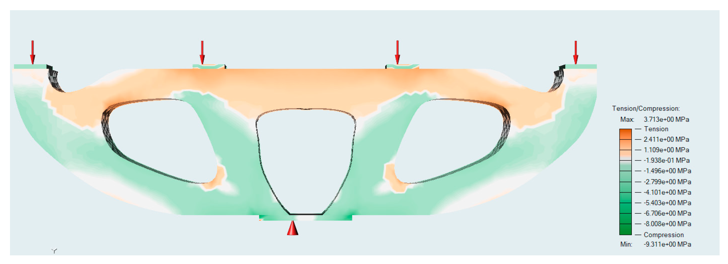
3.4. Failure Mechanism

As this research is a continuation of work reported by Salaimanimagudam et al. [22], the local compressive damage was spotted at the contact point of impact. From the beam’s top chord, the impact energy wave was transmitted by compression web to the bottom chord. The tension zone occurred at the mid of the top chord, which was subjected to dual impacts resulting in the stress wave crashing at the top chord between two compression webs. In the tension zone, there may be an air crack, shear plugin fibers may be local or global even fiber delimitation occurs in the worst cases with and the fiber rupturing; matrix failure may happen at the web and bottom chord. The numerous wave sway of impact energy in each particular step is delineated in Figure 14 [22]. This holds restricted local contact crushing due to the subjection of impact mass. The compression bending over an impact plane causes innermost deboning of beams due to the transverse shear stress/strain, break- down of matrix/fiber triggered. In the meantime, the tensile bending triggers the fiber deboning action, which spreads over an adjunct stratum of the tension zone. The stress wave generated by the drop weight impact is transmitted to densely packed fibers and aggregates skeleton, which leads to numerous micro-cracks formation.
Fiber-reinforced PAC can restrict crack propagation and energy-dissipation to the balance parts of the beam. Henceforth, a significant occasion in failure mechanism forms negative implications in the impact properties and is too complicated to predict this in process.

3.5. Number of Cracks and Failure Pattern

The number of main and secondary cracks is illustrated in Figure 15. In a nonfibrous concrete beam, HPB-0 having three main cracks at the top chord and one main and secondary crack at the bottom chord. Three main cracks were observed in the top chord of the specimen HPB-2 with eight secondary cracks. HPB-4 had a comparatively smaller main crack and many secondary cracks, two main cracks in the top chord, and seventeen secondary cracks throughout the beam. For HPB-2-T and HPB-4-T, both beams had the same 5 number of main cracks at the bottom chord and eleven and twelve secondary cracks.
The specimen HPB-0 brittle in nature disintegrates into four fragments at five repeated impact blows, and a failure pattern can be observed in Figure 16a. In the specimen, HPB-2 can be observed with a local compressive crush in the top chord due to repeated impact in Figure 16b. The global shear plug occurs at three places in the top chord of the beam. The local compressive damage is noticeable at the top chord of HPB-4 in Figure 16c, and transverse flexural cracks are observed at the bottom chord of the beam. The failure pattern of entirely fibrous concrete beam HPB-2 and HPB-4 are observed similar behavior in failure mechanism. In the HPB-2-T specimen, due to nonfibrous in the compression zone, the brittle failure at the bottom chord, which breaks into several fragments and local shear plugs, can be observed the top chord of the specimen.
Moreover, the new type of horizontal flexural cracks can be observed in the compressive web in Figure 12d. The major local compressive crush can be visible HPB-4-T in Figure 16. The number of main cracks evidences the brittleness of plain concrete in the compressive zone. The compressive web failed due to fibers’ addition only in the tension zone, and the same tendency of failure mechanism can be observed in HPB-2-T and HPB-4-T.

4. Conclusions

The following conclusions have been drawn up based on the above investigation.
The impact resistance of topology optimized Hammerhead Pier Beam have been investigated and the conclusions of the studies are presented below:
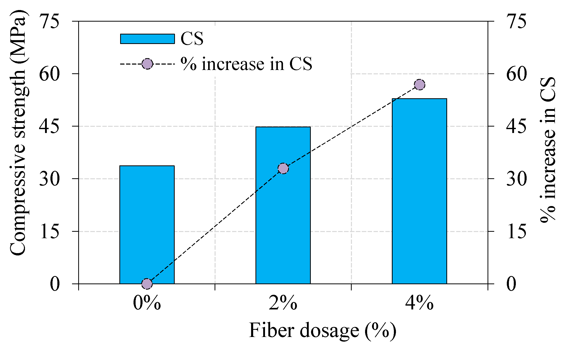
  • The compressive strength of concrete is increased when the dosage of fiber is increased. For instance, the compressive strength is increased by about 56.9%, when the corresponding dosage of steel fiber was 4%. Besides, the fiber balling is wholly eradicated due to the new casting techniques adopted for producing PAFC.
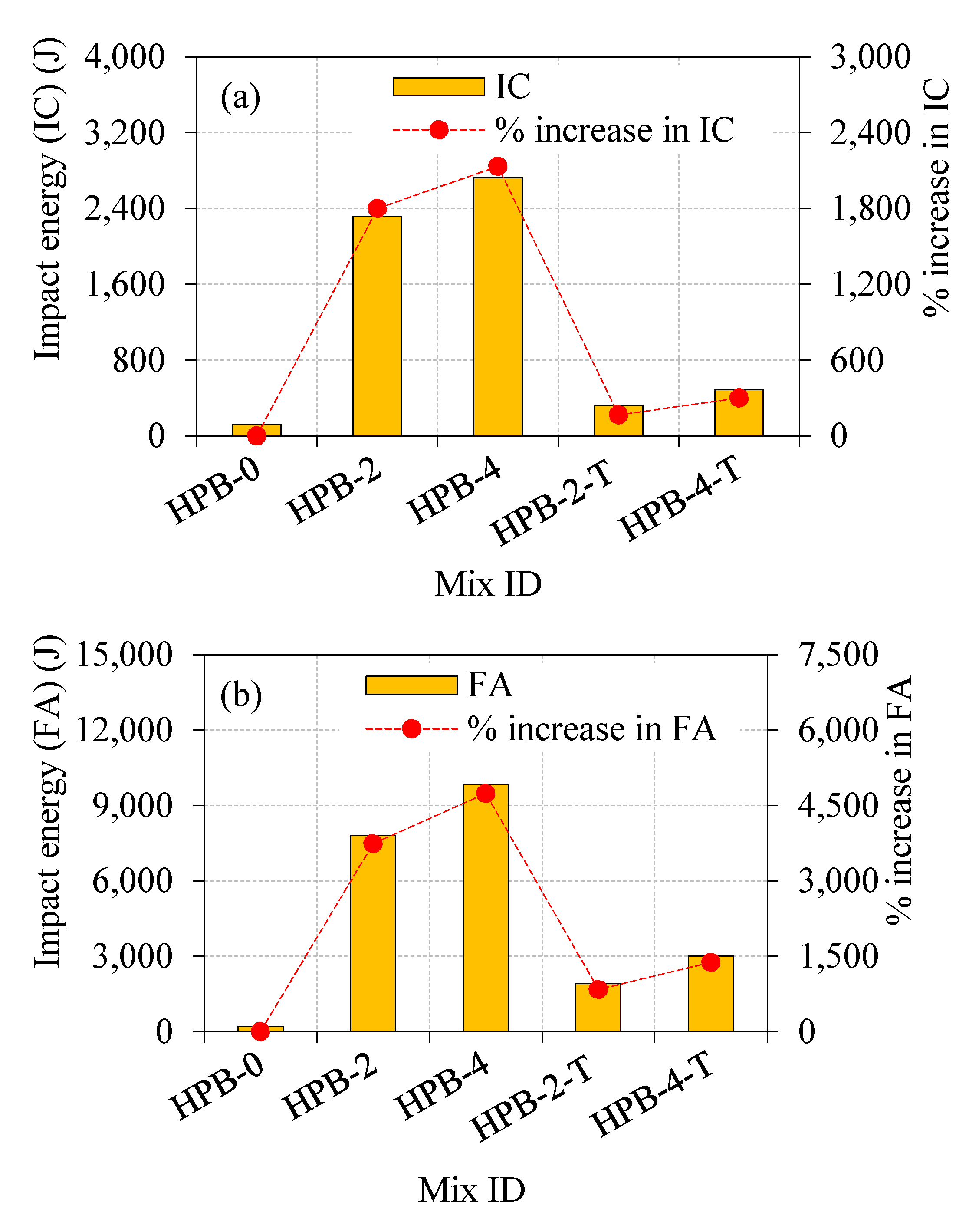
  • It is found that when the HPB-4 contained a 4% fiber dosage in full cross-section, the impact energy at initial crack and failure were 2725.1 J and 3009.8 J, respectively. This phenomenon is attributed to fiber steel fibers, which plays a crucial part in improving the impact energy absorbance of the cracking zone and adjoining crack tip by the action of fiber bridging, thus arresting cracks.
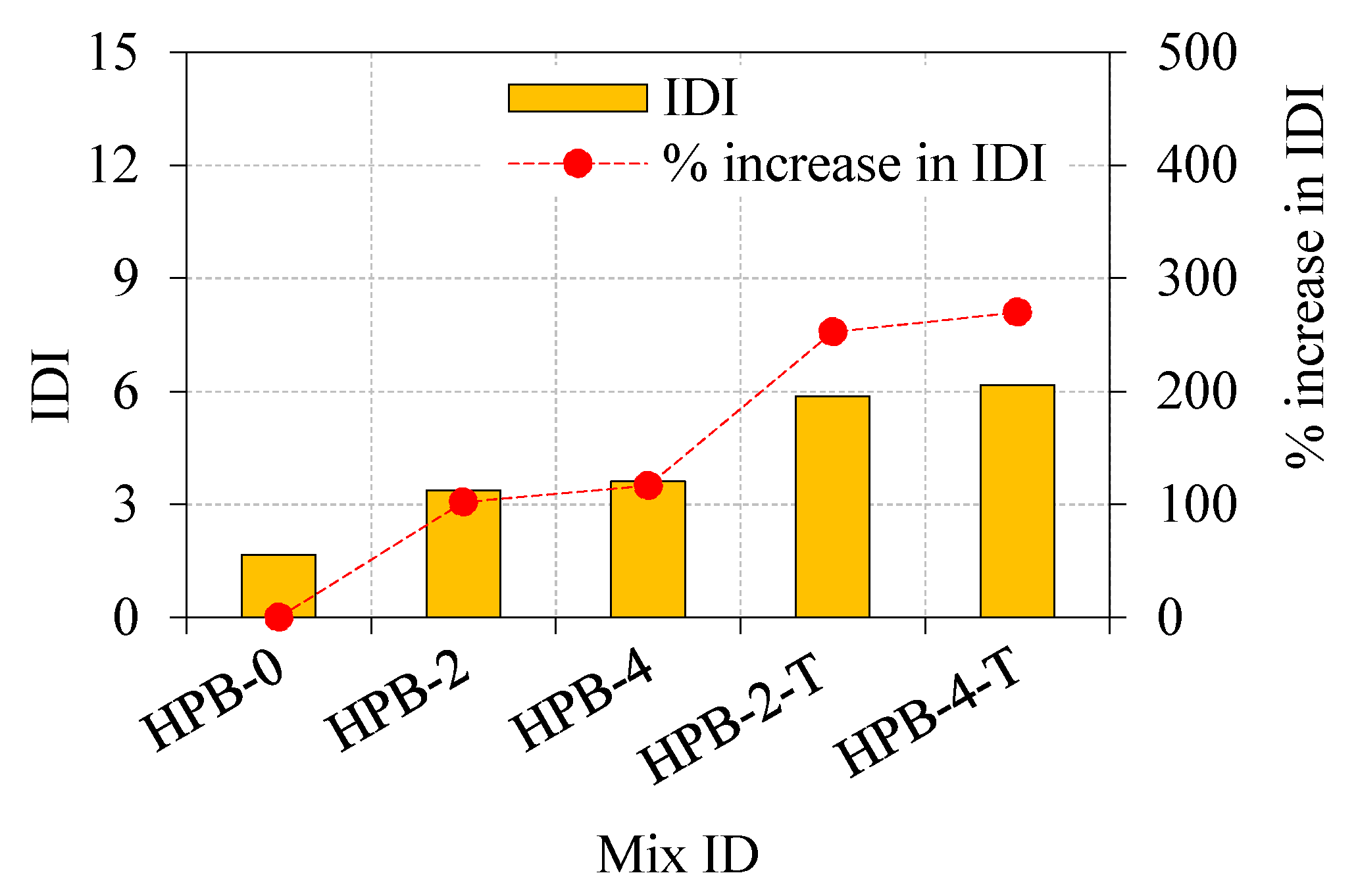
  • The highest impact ductility index was observed in HPB-4-T, followed by HPB-2-T due to the tensile strength of fiber and bridging action. The post crack resistance against impact load is much higher in the beam reinforced in the tensile zone than the beam reinforced in the full cross-section because of the more fibers provided at tensile zone.
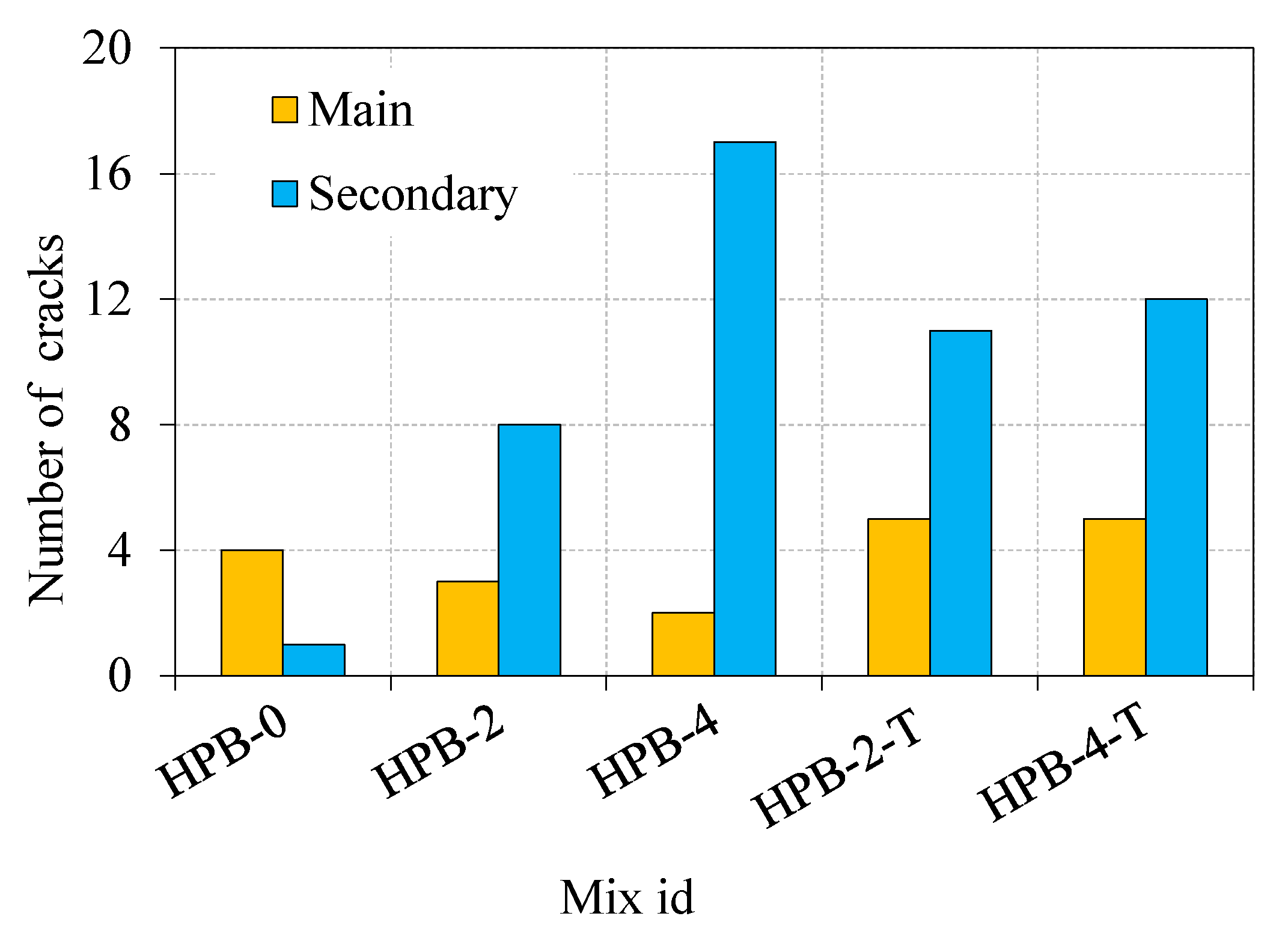
  • Two different failure modes were observed. First, brittle failure was observed in the non-fibrous beam due to the fibre’s absence. Second, all fibrous beams experienced a ductile failure resulting from fiber bridging action, which leads to multiple micro-cracks, thereby delaying the failure.

Author Contributions

Conceptualization, M.P.S., G.M.; methodology, M.P.S., G.M. validation, M.P.S. and G.M.; resources, M.P.S. and G.M.; visualization G.M.; writing—original draft preparation, G.M.; writing-review and editing, G.M. and C.M.V.V.; supervision, G.M. project administration, G.M.; funding acquisition, M.A., N.V., R.F. and Y.V. All authors have read and agreed to the published version of the manuscript.

Funding

The research is partially funded by the Ministry of Science and Higher Education of the Russian Federation as part of World-class Research Center program: Advanced Digital Technologies (contract No. 075-15-2020-934 dated 17 November 2020).

Acknowledgments

The authors gratefully acknowledge the support given by the SASTRA Deemed University, India.

Conflicts of Interest

The authors declare no conflict of interest.

References

  1. Bhattacherjee, S.; Rahul, A.V.; Santhanam, M. 3D Printing—Progress Worldwide. Indian Concr. J. 2020, 94, 8–25. [Google Scholar]
  2. Veenendaal, D.; West, M.; Block, P. History and overview of fabric formwork: Using fabrics for concrete casting. Struct. Concr. 2011, 12, 164–177. [Google Scholar] [CrossRef]
  3. Srivastava, S.; Salunkhe, S.; Pande, S.; Kapadiya, B. Topology optimization of steering knuckle structure. Int. J. Simul. Multidiscip. Des. Optim. 2020, 11, 4. [Google Scholar] [CrossRef]
  4. Shi, J.-F.; Sun, J.-H. Overview on Innovation of Topology Optimization in Vehicle CAE. In Proceedings of the 2009 International Conference on Electronic Computer Technology (ICECT 2009), Macau, China, 20–22 February 2009; pp. 457–460. [Google Scholar] [CrossRef]
  5. Yu, M.; Ruan, S.; Gu, J.; Ren, M.; Li, Z.; Wang, X.; Shen, C. Three-dimensional topology optimization of thermal-fluid-structural problems for cooling system design. Struct. Multidiscip. Optim. 2020, 62, 3347–3366. [Google Scholar] [CrossRef]
  6. Ruan, X.; Jiang, P.; Zhou, Q.; Hu, J.; Shu, L. Variable-fidelity probability of improvement method for efficient global optimization of expensive black-box problems. Struct. Multidiscip. Optim. 2020, 62, 3021–3052. [Google Scholar] [CrossRef]
  7. Vantyghem, G.; De Corte, W.; Steeman, M.; Boel, V. Density-based topology optimization for 3D-printable building structures. Struct. Multidiscip. Optim. 2019, 60, 2391–2403. [Google Scholar] [CrossRef]
  8. Carstensen, J.V. Topology optimization with nozzle size restrictions for material extrusion-type additive manufacturing. Struct. Multidiscip. Optim. 2020, 62, 2481–2497. [Google Scholar] [CrossRef]
  9. Liu, J.; Gaynor, A.T.; Chen, S.; Kang, Z.; Suresh, K.; Takezawa, A.; Li, L.; Kato, J.; Tang, J.; Wang, C.C.L.; et al. Current and future trends in topology optimization for additive manufacturing. Struct. Multidiscip. Optim. 2018, 57, 2457–2483. [Google Scholar] [CrossRef] [Green Version]
  10. Schmidt, M.-P.; Couret, L.; Gout, C.; Pedersen, C.B.W. Structural topology optimization with smoothly varying fiber orientations. Struct. Multidiscip. Optim. 2020, 62, 3105–3126. [Google Scholar] [CrossRef]
  11. Kabir, S.M.F.; Mathur, K.; Seyam, A.-F.M. A critical review on 3D printed continuous fiber-reinforced composites: History, mechanism, materials and properties. Compos. Struct. 2020, 232, 111476. [Google Scholar] [CrossRef]
  12. Tajs-Zielińska, K.; Bochenek, B. Topology Optimization—Engineering Contribution to Architectural Design. IOP Conf. Ser. Mater. Sci. Eng. 2017, 245, 082057. [Google Scholar] [CrossRef]
  13. Beghini, L.L.; Beghini, A.; Katz, N.; Baker, W.F.; Paulino, G. Connecting architecture and engineering through structural topology optimization. Eng. Struct. 2014, 59, 716–726. [Google Scholar] [CrossRef]
  14. D’Uva, D. Handbook of Research on form and Morphogenesis in Modern Architectural Contexts; IGI Global: Hershe, PA, USA, 2018; pp. 1–493. [Google Scholar] [CrossRef]
  15. Montes, M.A.O.; Ivvan, S.; Pe, V.; Rionda, S.B. Topology Optimization Algorithms for the Solution of Compliance and Volume Problems in 2D; Topology; Centro de Investigaci´on en Matem´aticas A.C.: Guanajuato, México, 2016. [Google Scholar]
  16. Sigmund, O.; Maute, K. Topology optimization approaches: A comparative review. Struct. Multidiscip. Optim. 2013, 48, 1031–1055. [Google Scholar] [CrossRef]
  17. Bendsøe, M.P.; Duysinx, P. Topology Optimizatin of Continuum Structures with Local Stress Constraints. Int. J. Numer. Methods Eng. 1998, 43, 1453–1478. [Google Scholar] [CrossRef]
  18. Bendsoe, M.P.; Sigmund, O. Topology Optimization Theory, Methods and Applications; Springer: Berlin/Heidelberg, Germany, 2003. [Google Scholar]
  19. Polajnar, M.; Kosel, F.; Drazumeric, R. Structural optimization using global stress-deviation objective function via the level-set method. Struct. Multidiscip. Optim. 2016, 55, 91–104. [Google Scholar] [CrossRef]
  20. Deaton, J.D.; Grandhi, R.V. A survey of structural and multidisciplinary continuum topology optimization: Post 2000. Struct. Multidiscip. Optim. 2014, 49, 1–38. [Google Scholar] [CrossRef]
  21. Picelli, R.; Townsend, S.; Brampton, C.; Norato, J.; Kim, H. Stress-based shape and topology optimization with the level set method. Comput. Methods Appl. Mech. Eng. 2018, 329, 1–23. [Google Scholar] [CrossRef]
  22. Jeong, S.H.; Yoon, G.H.; Takezawa, A.; Choi, D.-H. Development of a novel phase-field method for local stress-based shape and topology optimization. Comput. Struct. 2014, 132, 84–98. [Google Scholar] [CrossRef]
  23. Salaimanimagudam, M.P.; Suribabu, C.R.; Murali, G.; Abid, S.R. Impact Response of Hammerhead Pier Fibrous Concrete Beams Designed with Topology Optimization. Period. Polytech. Civ. Eng. 2020, 18, 1244–1258. [Google Scholar] [CrossRef]
  24. Xia, Y.; Langelaar, M.; Hendriks, M.A. Optimization-based three-dimensional strut-and-tie model generation for reinforced concrete. Comput. Aided Civ. Infrastruct. Eng. 2020, 1–18. [Google Scholar] [CrossRef]
  25. Xia, Y.; Langelaar, M.; Hendriks, M.A. A critical evaluation of topology optimization results for strut-and-tie modeling of reinforced concrete. Comput. Aided Civ. Infrastruct. Eng. 2020, 5, 850–869. [Google Scholar] [CrossRef] [Green Version]
  26. Jewett, J.L.; Carstensen, J.V. Topology-optimized design, construction and experimental evaluation of concrete beams. Autom. Constr. 2019, 102, 59–67. [Google Scholar] [CrossRef]
  27. Nehdi, M.L.; Najjar, M.F.; Soliman, A.M.; Azabi, T.M. Novel steel fibre-reinforced preplaced aggregate concrete with superior mechanical performance. Cem. Concr. Compos. 2017, 82, 242–251. [Google Scholar] [CrossRef]
  28. Najjar, M.F.; Soliman, A.M.; Nehdi, M. Critical overview of two-stage concrete: Properties and applications. Constr. Build. Mater. 2014, 62, 47–58. [Google Scholar] [CrossRef]
  29. Bras, A.; Gião, A.R.F.C.D.S.; Lúcio, V.; Chastre, C. Development of an injectable grout for concrete repair and strengthening. Cem. Concr. Compos. 2013, 37, 185–195. [Google Scholar] [CrossRef] [Green Version]
  30. Lee, S.; Jang, S.Y.; Kim, C.Y.; Ahn, E.J.; Kim, S.P.; Gwon, S.; Shin, M. Effects of Redispersible Polymer Powder on Mechanical and Durability Properties of Preplaced Aggregate Concrete with Recycled Railway Ballast. Int. J. Concr. Struct. Mater. 2018, 12, 69. [Google Scholar] [CrossRef]
  31. An, X.; Wu, Q.; Jin, F.; Huang, M.; Zhou, H.; Chen, C.; Liu, C. Rock-filled concrete, the new norm of SCC in hydraulic engineering in China. Cem. Concr. Compos. 2014, 54, 89–99. [Google Scholar] [CrossRef]
  32. Lv, J.; Zhou, T.; Li, K. Development and Investigation of a New Low-Cement-Consumption Concrete—Preplaced Aggregate Concrete. Sustainability 2020, 12, 1080. [Google Scholar] [CrossRef] [Green Version]
  33. Stempkowska, A.; Gawenda, T.; Naziemiec, Z.; Ostrowski, K.A.; Saramak, D.; Surowiak, A. Impact of the Geometrical Parameters of Dolomite Coarse Aggregate on the Thermal and Mechanic Properties of Preplaced Aggregate Concrete. Materials 2020, 13, 4358. [Google Scholar] [CrossRef]
  34. Yoon, J.; Kim, H.; Shin, S.W.; Sim, S.-H. Rheology-based determination of injectable grout fluidity for preplaced aggregate concrete using ultrasonic tomography. Constr. Build. Mater. 2020, 260, 120447. [Google Scholar] [CrossRef]
  35. Zhang, C.; Gholipour, G.; Mousavi, A.A. State-of-the-Art Review on Responses of RC Structures Subjected to Lateral Impact Loads. Arch. Comput. Methods Eng. 2020, 1–31. [Google Scholar] [CrossRef]
  36. Manohar, T.; Suribabu, C.R.; Murali, G.; Salaimanimagudam, M.P. A novel steel-PAFRC composite fender for bridge pier protection under low velocity vessel impacts. Structures 2020, 26, 765–777. [Google Scholar] [CrossRef]
  37. Zhang, C.; Gholipour, G.; Mousavi, A.A. Nonlinear dynamic behavior of simply-supported RC beams subjected to combined impact-blast loading. Eng. Struct. 2019, 181, 124–142. [Google Scholar] [CrossRef]
  38. Bruggi, M.; Taliercio, A. Topology optimization of the fiber-reinforcement retrofitting existing structures. Int. J. Solids Struct. 2013, 50, 121–136. [Google Scholar] [CrossRef] [Green Version]
  39. Bruggi, M. Topology optimization with mixed finite elements on regular grids. Comput. Methods Appl. Mech. Eng. 2016, 305, 133–153. [Google Scholar] [CrossRef] [Green Version]
  40. Osanov, M.; Carstensen, J.V.; Tromme, E.M.; Guest, J.K.; Williams, C. Topology Optimization for Additive Manufacturing: New Projection-based Design Algorithms. In Proceedings of the 17th AIAA/ISSMO Multidisciplinary Analysis and Optimization Conference, Washington, DC, USA, 13–17 June 2016; pp. 1–9. [Google Scholar] [CrossRef]
  41. Jaishankar, P.; Murali, G.; Salaimanimagudam, M.P.; Amran, Y.H.; Fediuk, R.; Karthikeyan, K. Study of Topology Optimized Hammerhead Pier Beam Made with Novel Preplaced Aggregate Fibrous Concrete. Period. Polytech. Civ. Eng. 2020, 65, 287–298. [Google Scholar] [CrossRef]
  42. IS 1489-1. Specification for Portland Pozzolana Cement. India. 1991. Available online: https://archive.org/details/gov.in.is.1489.1.1991/page/n7/mode/2up (accessed on 31 January 2021).
  43. IS:383-2016. Coarse and Fine Aggregate for Concrete—Specification, (Third Revision), India. 2016. Available online: http://skgcgroup.com/wp-content/uploads/2020/02/IS%20383-2016.pdf (accessed on 31 January 2021).
  44. American Society for Testing and Materials (ASTM). Sandard Test Methods for Flow of Grout for Preplaced-Aggregate Concrete (Flow Cone Method); ASTM: West Conshohocken, PA, USA, 2010. [Google Scholar]
  45. ACI544.2R-89. Measurement of Properties of Fibber Reinforced Concrete; ACI: West Conshohocken, PA, USA, 1999. [Google Scholar]
  46. Abid, S.R.; Hussein, M.L.A.; Ali, S.H.; Kazem, A.F. Suggested modified testing techniques to the ACI 544-R repeated drop-weight impact test. Constr. Build. Mater. 2020, 244, 118321. [Google Scholar] [CrossRef]
  47. Rithanyaa, R.; Murali, G.; Salaimanimagudam, M.; Fediuk, R.; Abdelgader, H.S.; Siva, A. Impact response of novel layered two stage fibrous composite slabs with different support type. Structures 2021, 29, 1–13. [Google Scholar] [CrossRef]
  48. Abid, S.R.; Murali, G.; Amran, M.; Vatin, N.; Fediuk, R.; Karelina, M. Evaluation of Mode II Fracture Toughness of Hybrid Fibrous Geopolymer Composites. Materials 2021, 14, 349. [Google Scholar] [CrossRef]
  49. Abid, S.R.; Gunasekaran, M.; Ali, S.H.; Kadhum, A.L.; Al-Gasham, T.S.; Fediuk, R.; Vatin, N.; Karelina, M. Impact Performance of Steel Fiber-Reinforced Self- Compacting Concrete against Repeated Drop Weight Impact. Crystals 2021, 11, 91. [Google Scholar] [CrossRef]
  50. Prasad, N.; Murali, G.; Fediuk, R.; Vatin, N.; Karelina, M. Response of Novel Functionally-Graded Prepacked Aggregate Fibrous Concrete against Low Velocity Repeated Projectile Impacts. Materials 2021, 14, 280. [Google Scholar] [CrossRef] [PubMed]
  51. Loganaganandan., M.; Murali, G.; Salaimanimagudam, M.P.; Haridharan, M.P.; Karthikeyan, K. Experimental Study on GFRP Strips Strengthened New Two Stage Concrete Slabs under Falling Mass Collisions. KSCE J. Civ. Eng. 2021, 25, 235–244. [Google Scholar] [CrossRef]
  52. Murali, G.; Amran, M.; Fediuk, R.; Vatin, N.; Raman, S.N.; Maithreyi, G.; Sumathi, A. Structural Behavior of Fibrous-Ferrocement Panel Subjected to Flexural and Impact Loads. Materials 2020, 13, 5648. [Google Scholar] [CrossRef] [PubMed]
  53. Prasad, N.; Murali, G. Exploring the impact performance of functionally-graded preplaced aggregate concrete incorporating steel and polypropylene fibres. J. Build. Eng. 2021, 35, 102077. [Google Scholar] [CrossRef]
  54. Jabir, H.A.; Abid, S.R.; Murali, G.; Ali, S.H.; Klyuev, S.; Fediuk, R.; Vatin, N.; Promakhov, V.; Vasilev, Y. Experimental Tests and Reliability Analysis of the Cracking Impact Resistance of UHPFRC. Fibers 2020, 8, 74. [Google Scholar] [CrossRef]
  55. Murali, G.; Abid, S.R.; Amran, Y.H.M.; Abdelgader, H.S.; Fediuk, R.; Susrutha, A.; Poonguzhali, K. Impact performance of novel multi-layered prepacked aggregate fibrous composites under compression and bending. Structures 2020, 28, 1502–1515. [Google Scholar] [CrossRef]
  56. Amran, M.; Fediuk, R.; Vatin, N.; Huei Lee, Y.; Murali, G.; Ozbakkaloglu, T.; Klyuev, S.; Alabduljabber, H. Fibre-Reinforced Foamed Concretes: A Review. Materials 2020, 13, 4323. [Google Scholar] [CrossRef]
  57. Haridharan, M.K.; Matheswaran, S.; Murali, G.; Abid, S.R.; Fediuk, R.; Amran, Y.H.M.; Abdelgader, H.S. Impact response of two-layered grouted aggregate fibrous concrete composite under falling mass impact. Constr. Build. Mater. 2020, 263, 120628. [Google Scholar] [CrossRef]
  58. Abirami, T.; Murali, G.; Saravana Raja Mohan, K.; Salaimanimagudam, M.P.; Nagaveni, P.; Bhargavi, P. Multi-layered two stage fibrous composites against low-velocity falling mass and projectile impact. Constr. Build. Mater. 2020, 248, 118631. [Google Scholar] [CrossRef]
  59. Murali, G.; Fediuk, R. A Taguchi approach for study on impact response of ultra-high-performance polypropylene fibrous cementitious composite. J. Build. Eng. 2020, 30, 101301. [Google Scholar] [CrossRef]
  60. Murali, G.; Laxminadh, P.; Parthiban, K.; Haridharan, M.K.; Siva, A. Impact Response of Novel Fibre-Reinforced Grouted Aggregate Rubberized Concrete. Arab. J. Sci. Eng. 2019, 44, 8451–8463. [Google Scholar] [CrossRef]
  61. Abirami, T.; Loganaganandan, M.; Murali, G.; Fediuk, R.; Vickhram Sreekrishna, R.; Vignesh, T.; Januppriya, G.; Karthikeyan, K. Experimental research on impact response of novel steel fibrous concretes under falling mass impact. Constr. Build. Mater. 2019, 222, 447–457. [Google Scholar] [CrossRef]
  62. Ramkumar, V.R.; Murali, G.; Asrani, N.P.; Karthikeyan, K. Development of a novel low carbon cementitious two stage layered fibrous concrete with superior impact strength. J. Build. Eng. 2019, 25, 100841. [Google Scholar] [CrossRef]
  63. Asrani, N.P.; Murali, G.; Parthiban, K.; Surya, K.; Prakash, A.; Rathika, K.; Chandru, U. A feasibility of enhancing the impact resistance of hybrid fibrous geopolymer composites: Experiments and modelling. Constr. Build. Mate. 2019, 203, 56–68. [Google Scholar] [CrossRef]
  64. Murali, G.E.; Vinodha, E. Experimental and Analytical Study of Impact Failure Strength of Steel Hybrid Fibre Reinforced Concrete Subjected to Freezing and Thawing Cycles. Arab. J. Sci. Eng. 2018, 43, 5487–5497. [Google Scholar] [CrossRef]
  65. Murali, G.; Ramprasad, K. A feasibility of enhancing the impact strength of novel layered two stage fibrous concrete slabs. Eng. Struct. 2018, 175, 41–49. [Google Scholar] [CrossRef]
  66. Murali, G.; Venkatesh, J.; Lokesh, N.; Reddy, N.T.; Karthikeyan, K. Comparative Experimental and Analytical Modeling of Impact Energy Dissipation of Ultra-High Performance Fibre Reinforced Concrete. KSCE J. Civ. Eng. 2018, 22, 3112–3119. [Google Scholar] [CrossRef]
Figure 1. Topology optimization framework comparison.
Crystals 11 00147 g001
Figure 2. Single constraints model example of OCM.
Crystals 11 00147 g002
Figure 3. Multiple constraints model example of MMA.
Crystals 11 00147 g003
Figure 4. Field of the design domain with displacement and prescribed load constraints.
Crystals 11 00147 g004
Figure 5. Minimum compliance of topology optimized HPB.
Crystals 11 00147 g005
Figure 6. Geometric shape of steel fibers.
Crystals 11 00147 g006
Figure 7. Compression and Tension zone in TOHPB.
Crystals 11 00147 g007
Figure 8. Fiber dosage layout in TOHPB (a) HPB-0 (b) HPB-2 (c) HPB-4 (d) HPB-2-T and (e) HPB-4-T.
Crystals 11 00147 g008
Figure 9. Casting method of PAFC (a) empty framework (b) fibers and aggregates were filled in framework (c) pouring of grout and (d) finished beams.
Crystals 11 00147 g009
Figure 10. Impact test setup.
Crystals 11 00147 g010
Figure 11. Compressive strength of PAFC.
Crystals 11 00147 g011
Figure 12. Impact energies at initial crack and failure (a) Impact energy at IC and (b) Impact energy at FA.
Crystals 11 00147 g012
Figure 13. Impact ductility index.
Crystals 11 00147 g013
Figure 14. Failure mechanism [22].
Crystals 11 00147 g014
Figure 15. The observed number of cracks under impact loading.
Crystals 11 00147 g015
Figure 16. Failure pattern TOHPB (a) HPB-0 (b) HPB-2 (c) HPB-4 (d) HPB-2-T and (e) HPB-4-T.
Crystals 11 00147 g016
Table 1. Similitude relation.
TypePhysical QuantitySimilitude RelationSimilitude Parameter
GeometryLength (L) N L 1:20
Displacement (δ) N δ 1:20
Material propertiesElastic modulus, (E) N E 1
Stress (σ) N σ 1
LoadsStrain (ε) N ε 1
Force (F) N F 1:400
Table 2. Properties of used fibers in this study.
Fiber TypeTensile Strength (MPa)Diameter (mm)Length (mm)
Hybrid hooked end-crimped1150150
Table 3. Mix composition.
Mixture IDW/B S/Bt
(Sec)
Fiber Dosage (%)SP
(%)
Tension RegionCompression Region
HPB-00.421.036000.3
HPB-239220.5
HPB-43944
HPB-2-T 3920
HPB-4-T3940
Table 4. Impact test results.
Mix IdNumber of HitsImpact Energy (J)Impact Ductility IndexNo of Cracks
ICFAICFAMajorMinor
HPB-035122.0203.41.741
HPB-2571922318.47809.23.438
HPB-4672422725.19842.93.6217
HPB-2-T 847325.41911.65.9511
HPB-4-T1274488.13009.86.2512
Publisher’s Note: MDPI stays neutral with regard to jurisdictional claims in published maps and institutional affiliations.

