Article

The Analysis and Design of a High Efficiency Piezoelectric Harvesting Floor with Impacting Force Mechanism

Department of Mechanical Engineering, Southern Taiwan University of Science and Technology, Tainan 71005, Taiwan
*
Author to whom correspondence should be addressed.
Crystals 2021, 11(4), 380; https://doi.org/10.3390/cryst11040380
Submission received: 8 November 2020 / Revised: 27 March 2021 / Accepted: 30 March 2021 / Published: 6 April 2021
(This article belongs to the Special Issue Piezoelectric Materials and Technology)

Abstract

:
In renewable energy technology development, piezoelectric material has electro-mechanical converted capability and the advantages of simple construction and compact size, it has potential development since the environment vibration can be transferred into an electrical energy in daily harvesting applications. To improve the electro-mechanical converted efficiency of a piezoelectric harvester at low-frequency environment, a free vibration type of piezoelectric cantilever harvesting structure was proposed, which can generate a resonant oscillation by releasing an initial deformed displacement, and was uninfluenced from the effects of external environment. To analyze the harvesting behaviors, an equivalent circuit with voltage source was provided, and the parameters in theoretical model can be determined by the dimensions of the piezoelectric unimorph plate and its initial deformation. From the comparison of measurement and simulation, it reveals a significant efficient theoretical model where 8% error occurrence for storage energy was found. Finally, the proposed free-vibration generation method was developed in a piezoelectric harvesting floor design, which can transfer human walking motion into electric energy, and store in an external storage capacitor. From the testing result, one time of footstep motion can cause the charging energy in a 33 μF of storage capacitor achieve to 0.278 mJ, which was larger than the driven power of the wireless transmitter module, and then the wireless transmitter can be driven to send a RF signal without external power supply. Therefore, the designed piezoelectric harvesting floor has potential development to locate the user’s current position, which can provide users with future appropriate service for intelligent building application.

1. Introduction

In the recent years, depending on the tendency of miniaturization and low-power consumption in electronic product development, a self-powered electric device with autonomous energy has attracted a lot of interest, especially for wireless-sensor network technologies in intelligent living and industrial applications, such as public stations, commercial buildings, and manufacturing factories [1]. For example, in intelligent architecture application designated to provide users with the most appropriate service inside the intelligent buildings, locating the user’s current position is essential. To implement a self-powered wireless sensor, energy harvesting technologies from ambient environments, such as solar, wind, tidal, and geothermal energy should be developed for the purpose of driving a low-power electronic device with sustainable electrical energy source [2,3,4,5]. In these energy harvesting technologies, the piezoelectric material has the advantages of simple construction, compact size, and high efficiency in energy conversion [6], and has been widely investigated to be utilized in daily harvesting applications [7]. In order to obtain the best harvesting efficiency, a cantilever beam construction was developed for its capacity of large deformation in the most piezoelectric harvester, and its structure resonance frequency should be appropriated to the exciting frequency from the external environment [8]. However, the oscillation produced from the ambient environment is unstable, and the frequency is lower than the resonance frequency of the piezoelectric harvester, which results in the decreasing electro-mechanical conversion efficiency. To improve the harvesting efficiency, some methods for matching the environment oscillation frequency were provided in the research literature. For example, changing the weight of a mounted mass on the front end of a cantilever beam was proposed to affect the structure resonance frequency [9]. Another method was combined in parallel with numerous piezoelectric cantilever beams with the different dimensions and the weight of a mounted mass to obtain a range of operation frequency [10]. In order to obtain the resonant vibration of the piezoelectric harvesters in unstable ambient oscillation, Umeda et al. designed using a steel ball to strike a piezoelectric monomorphic disc to induce resonant vibrations to achieve high electric power output [11]. However, sometimes the striking force of a steel ball interferes with the beam motion results in a fluctuation of voltage generation, and electric power output is reduced significantly [12]. To ensure the sufficient striking motion, a plucking mechanism used in exciting piezoelectric cantilevers, which induces an initial deflection in the cantilever and then lets it vibrate freely at its resonance frequency, was proposed in recent literature and developed to different plucking methods, including magnetic plucking [13,14], impact-driven [15,16], and mechanical plucking [17]. Therefore, in this study, our purpose was to design a mechanical plucking mechanism to develop a piezoelectric harvesting floor structure. To avoid the continuous impact force to disturb the free vibration, the plucking mechanism was designed to depend on the operation environment, and two times of free vibration can be excited to generate sufficient electric power to drive a wireless transmission model. To predict the electric energy generation from the piezoelectric harvesting floor, a theoretical model should be built. A piezoelectric energy harvester equivalent circuit, which consists of mechanical domain clarifying the direct effect of the piezoelectric materials, was generally proposed to represent the voltage output according to the responses of the force changes over the time [18]. Even the equivalent circuit model can be used to analyze the waveform of electric responses, the electric generation value from piezoelectric cantilevers was unable to be directly observed and experimental verification for electromechanically coupled beams was hard to be achieved. Considering that the electric power was converted and generated from the mechanical stress or strain distribution on piezoelectric cantilevers depending on the external mechanical loading, Pozzi [19] proposed a finite element (FE) model to predict the performances of the mechanically plucked piezoelectric cantilevers during the whole plucking cycle. Pillatsch [20] developed an FE analytic model used in the performance prediction of a magnetically plucked bimorph, and Kuang [21] developed a coupled piezoelectric-circuit finite element model to obtain the electric characteristics of equivalent circuits. However, the FE model only analyzes the dynamic mechanical responses with a single dimension, and the ability of performance design optimization was hard to be achieved. The other way was proposed to formulate the governing equations of the Euler-Bernoulli beam [22,23]. According to the assumption of boundary condition, the deformed distribution with rectangular bimorph or unimorph cantilever can be estimated with tip mass under base excitation reported in Reference [24]. Moreover, the excitations around resonance of cantilevered bimorphs were reduced to a single mode relation and combined with the electromechanical coupling effect to obtain the coupled voltage response across the resistive load and the coupled vibration response of the harvester explicitly for harmonic base excitations. Then, a short equivalent circuit with voltage source can be investigated extensively to predict harvesting electrical energy [12]. Different from most literature in which the plucking process was modeled as a stable force applied to the beam, and the characteristics of plucking piezoelectric energy harvesters would be hard to investigate due to experimentally validation of impact force difficulty, this paper used the Euler-Bernoulli governing equations to estimate the deformed distribution of the unimorph cantilever excited by an initial plucking displacement. An equivalent electromechanical model was proposed to represent mechanical characteristics of the resonance vibration in the plucking process, and converted into an equivalent circuit of the theoretical model to obtain the electric power output from the unimorph piezoelectric cantilever. Finally, the storage situation of external capacitance can be analyzed by circuit simulation software and demonstrated in the designed piezoelectric harvesting floor, which has sufficient harvesting efficiency to drive a wireless transmitter by one time of footstep motion.

2. Theoretical Analysis of Piezoelectric Cantilever Beam with Free Vibration

2.1. Deformation Analysis

To analyze the mechanical properties of piezoelectric beams, assume that an external force distribution f ( x , t ) was applied on the piezoelectric cantilever beam surface to result in a deformed displacement as presented in Figure 1. Based on the internal moment balance condition, the lateral deformation distribution in z-direction w ( x ,   t ) can be calculated by Euler–Bernoulli beam equation as [22]:
2 M ( x ,   t ) x 2 + f ( x , t ) = ρ A ( x ) 2 w ( x , t ) t 2 ,
where ρ was the mass density, A the cross-section area of the cantilever beam which was non-variation by the uniform beam assumption. E was the material Young’s modulus, and I was the cross-section moment of inertia with respect to the neutral axis. In this study, consider the uniform beam and Free vibration condition, based on thin beam theory [25], Equation (1) can be rewritten as:
E I 4 w ( x ,   t ) x 4 + ρ A 2 w ( x , t ) t 2 = 0 .
Meanwhile, based on the successive derivatives of lateral deformation w(x, t), the bending moment in the beam can be obtained from:
M = E I 2 w ( x ,   t ) x 2 .
From observing Equation (2) as a convergent series of the eigen-function, the beam displacement w ( x , t ) can be calculated by using a separation variable method as:
w ( x , t ) = W ( x ) T ( t ) ,
where   W ( x ) and T ( t ) are the scalar and time items of the normalized eigenfunction, and the mechanical equation as Equation (2) can be further reduced to the model coordinated in the free vibration model.
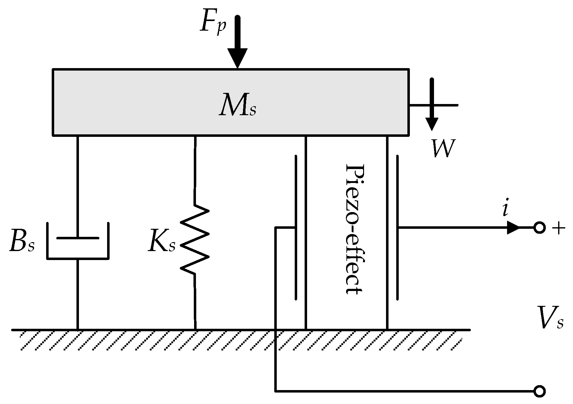
In this paper, an equivalent impact force by releasing an initial deformed displacement was utilized to generate a free vibration motion on the piezoelectric cantilever beam. To describe the free vibration of mechanical properties, an equivalent mass-spring-damper (MSD) model with a single degree of freedom [8,9], which consists of an equivalent mass Ms parallel connected with a spring Ks and a viscous damper Bs, was proposed to represent the mechanical response by an external loading. Meanwhile, the deformed displacement can also be converted into the electric energy by the piezoelectric effect, as shown in Figure 2. According to the equivalent mechanical model, with the application of an external impact force ( F ( t ) = δ ( t ) ), the deformed displacement w(t) with continuous time domain can be calculated as [25]:
w ( t ) = | W | e ξ ω n t cos ( ω n 1 ξ 2 t ) ,
where ω n was system natural frequency of equivalent mechanical model that can be equaled as ω n = K s M s ; ξ was its system damping coefficient being equaled as ξ = B s 2 K s M s . Observing Equation (5), the mechanical response can be separated into amplitude and time element. In our study, referring Equation (3) and Equation (5), the time item of the vibration displacement w ( x , t ) for cantilever beam was represented as [26]:
T ( t ) = e ξ ω n t cos ( ω d t ) ,
where ω d = ω n 1 ξ 2 is known as the damped natural frequency of the system. In general, for the cantilever beam structure in free vibration condition, the system damping coefficient ξ was too small to ignore its influence, which means that the exciting vibration frequency is the same as the system resonance frequency.
For a piezoelectric harvester, the deformed displacement will be converted into the electric energy as shown in Figure 2. However, the deformation amplitude in Equation (5) is not a fixed value for the cantilever structure. In this paper, in order to obtain the deformation distribution, the cantilever beam of a piezoelectric harvester was utilized for analyses, and the structure was shown as Figure 3. A piezoelectric plate is adhered to a steel plate substrate to be a two-layer of unimorph plate, and the piezoelectric plate should be located around the middle of the bender to obtain higher deformation. In this paper, consider the piezoelectric plate obtaining a large deformation, its adhered position should have an interval distance from the fixed support. Therefore, in the theoretical analysis, the unimorph plate can be separated into three parts to calculate the deformation in each section, which was presented in Figure 3. Moreover, ts and tp were defined as the thickness of steel and piezoelectric layer, respectively, and layers of Young’s modulus were presented as Es and Ep. Consider that the deformation was distributed along transverse direction (x-direction), by previously separation variable method, Equation (2) can be rewritten as:
E I ρ A W ( x ) W ( x ) = T ¨ ( t ) T ( t ) = β 4 ( c o n s t a n t ) ,
where β was a constant proportional relation. Observing Equation (7), the mechanical deformation equation can be separated into terms of relative displacement W ( x ) and time T ( t ) , and then the deformed displacement related with the transverse position can be obtained as the following:
4 W ( x ) x 4 ρ A E I β 4 W ( x ) = 0 .
According to the differential transformation method (DTM) [22,28], the solution of the homogeneous differential Equation (8) is presented in the following form:
W ( x ) = C 1 cosh ( λ x ) + C 2 sinh ( λ x ) + C 3 cos ( λ x ) + C 4 sin ( λ x ) .
To simplify the derivations, in this paper, the deformed shape of the cantilever beam was re-described by a polynomial equation form and separated into three sections from Figure 3 as the following:
In   Sec tion   A ,   W a ( x a ) = n = 0 3 a n x n = a 0 + a 1 x + a 2 x 2 + a 3 x 3 , In   Sec tion   B ,   W b ( x b ) = n = 0 3 b n x n = b 0 + b 1 x + b 2 x 2 + b 3 x 3 , In   Sec tion   C ,   W c ( x c ) = n = 0 3 c n x n = c 0 + c 1 x + c 2 x 2 + c 3 x 3 ,
where the ratio coefficients of Equation (10) as an, bn, and cn, were represented as amplitude of bending deformation in the cantilever beam, and can be determined by the boundary conditions of the cantilever beam as follows:
f ( x ) = E I d 4 W ( x ) d x 4 = 0   in   Sec tions   A ,   B ,   and   C , W ( x ) = 0   at   x a = 0   in   Sec tion   A , d W ( x ) d x = 0   at   x a = 0   in   Sec tion   A , τ ( x ) = E I d 3 W ( x ) d x 3 = F   at   x c = L c   in   Sec tion   C , M ( x ) = E I d 2 W ( x ) d x 2 = 0   at   x c = L c   in   Sec tion   C .
From the boundary condition, the internal stress and moment in the cantilever beam were related with the Young’s modulus E and inertia moment of sectional area I, respectively. In order to determine the Young’s modulus and inertia moment of the middle area (Section B), the transformed-section method [29] was utilized for a composite unimorph structure, which the width of piezoelectric plate variable depending on the Young’s modulus comparison, and modular ratio relation of width variation n was determined as:
n = E p E s , .  
where E p . and E s . denote the piezoelectric and steel layers of Young’s modulus, respectively. It can be found from Figure 4 that the Young’s modulus in the composite unimorph section can become the same as the steel material by the transformed-section method. According to the transformed sectional area in Figure 4b, the equivalent inertia moment in the composite unimorph secon Ib can be determined as:
I b = 1 12 b t s 3 + 2 [ 1 12 n b t p 3 + n b t p ( t s 2 + t p 2 ) 2 ] .
Moreover, in this study, an initial deformed displacement was proposed to be equivalent as an impact force, and the boundary condition in the end of the cantilever beam can be re-written as:
W c ( x c ) | x c = L c = Δ 0 = c 0 + c 1 L c + c 2 L c 2 + c 3 L c 3 = F S e q ,
where S e q is defined as the transformed coefficient from external force into deformed displacement W c ( x c ) , and based on the relationship between the beam’s deflection and the applied load ( E I d 4 W ( x ) d x 4 = F ), the transformed coefficient S e q can be estimated as:
S e q = 1 12 E s I a [ L a 3 + 3 L a 2 ( L b + 2 L c ) + 6 L a ( L b 2 + 2 L c 2 ) + 18 L a L b L c ] + 1 12 E s I b [ L b 3 + 6 L b L c ( L b + 2 L c ) ] + L c 3 3 E s I c .
Therefore, according to the boundary conditions of Equation (11), considering the boundary of internal stress and deformed strain in each section of the cantilever beam was assumed as a continuous distribution, then the ratio coefficient of Equation (10) can be determined as shown in Table 1. In the piezoelectric harvester, the electric energy was generated from the deformation of the piezoelectric plate. Therefore, the deformation distribution in unimorph section (Section B) in Equation (10) can be calculated from ratio coefficient of Table 1 and presented as:
W b ( x b ) = Δ 0 S e q [ ( L a 3 + 3 L a 2 L b + 6 L a 2 L c ) 12 E s I a + ( L a L b + 2 L a L c ) 2 E s I a x b + ( L b + 2 L c ) 4 E s I b x b 2 1 6 E s I b x b 3 ]
Moreover, combined with Equation (5), the internal axial stress applied in the piezoelectric unimorph plate can be estimated as:
T 1 ( x b , z , t ) = E p z d 2 W b d x b 2 T ( t ) = E p Δ 0 s e q [ ( L b + 2 L c ) 2 E b I b 1 E b I b x b ] z e ξ ω n t cos ( ω n t )

2.2. Electric Generating Analysis

During the free vibration process, the lateral deformation was occurred on the piezoelectric plate by its electro-mechanical converting capacity, and such a phenomenon was called the direct piezoelectric effect. From the previously description, the mechanical response of a piezoelectric harvester from an external loading was described in Figure 2. Moreover, to represent the electric response, an equivalent harvesting circuit was proposed and converted from the equivalent mechanical model of Figure 2, shown as Figure 5. It can be found that the mass-spring-damper (MSD) model can be equaled to a voltage source Vp serial connected with a capacitor C m , resistance R m , and inductance L m , which the electromechanical transferring relationship can be represented as:
R m = B s ,   L m = M s ,   C m = 1 K s .
Referring to Figure 2, whenever an external force Fp is being applied to deform the piezoelectric structure, which can be equaled to the voltage source Vp in mechanical port circuit, and the voltage output would be generated according to the responses of the force changes over the time [18]. Therefore, the inner stress of the piezoelectric material can be equaled to the cross voltage of the mechanical port circuit. based on Kirchhoff’s voltage law, the voltage-current relationship can be estimated, and represented to a Laplace form as:
V m = V P ( L m s 2 + R m s + 1 C m ) i m s
where s is denoted the s domain in Laplace transform which is converted from time domain. In our case, an initial deformed displacement was proposed to generate a free vibration situation, which means that the voltage source in the mechanical port circuit was assumed as zero ( V P = 0 ), and then it can be found that the electrical energy generated by piezoelectric effect is equaled to be an electric current source ( i m ). Consider that the free vibration is excited from an impact force to be converted into a pulse of voltage generated in the equivalent circuit, the electric generating function with continuous time domain can be calculated from the inverse Laplace transformation as:
i m ( t ) = L 1 [ i m ( s ) ] = | A | e R m 2 L m t c o s   ( 1 2 L m 4 L m C m R m 2 t + θ ) .
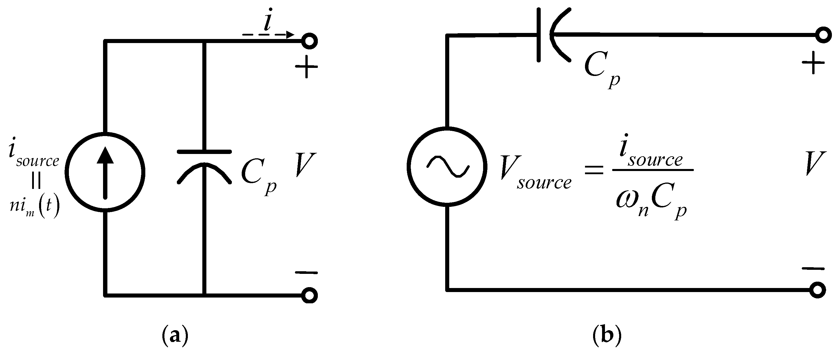
It can be found that Equation (19) of electric energy generation is similar to Equation (17) of the internal axial stress distribution, which consists of the scalar and time domain. Therefore, it can be demonstrated that the electric energy generation is related to the internal stress distribution and is estimated by the equivalent circuit for the free vibration process. Moreover, the mechanical port circuit in the equivalent circuit as Figure 5 can be simplified to be an electric current source as shown in Figure 6a.
To obtain the equivalent electric current source as mentioned previously in the free vibration process, the electro-mechanical converting relationship can be represented by the piezoelectric constitutive equation in strain-charge form with d-type as following [31]:
D 3 = d 31 T 1 + ε 33 T E 3
where T 1 and E 3 are the mechanical stress and electric field of system input and result in the mechanical and electrical generation of strain S 1 and electric displacement D 3 , respectively. The independent in-out relation is defined that the electric permittivity coefficient ε 33 T under constant strain, which the electric-mechanic coupling relation is presented as the piezoelectric coefficient d31. Finally, the subscripts of variables are the respective in-out applied directions, where they denote the horizontal and polarized direction as 1 and 3, respectively. From internal axial stress calculation of Equation (17), based on the Gauss law [32], the electric charge Q on the surface can be calculated as:
Q = D 3 d A = d 31 T 1 d A ε 33 T E 3 d A = d 31 E p b ( t s + t p ) L b L c E s I b s e q Δ 0 e ξ ω n t cos ( ω n t ) 2 ε 33 T L b b t p V = K t Δ 0 e ξ ω n t cos ( ω n t ) C p V ,
where C p is defined as equivalent internal capacitance, and K t a dimension coefficient. Therefore, according to Equation (21), the electric current generating from the piezoelectric unimorph plate with free vibration can be estimated as:
i = d d t ( Q ) K t Δ 0 e ξ ω n t sin ( ω n t + π ) C p d V d t .
From Equation (22), it can be found that the piezoelectric material has a capacitance characteristic to affect electric current output, and the generation value with free vibration mode can be calculated from initial deformation of the unimorph plate ( Δ 0 ). In order to analyze the electric behaviors of the storage circuit, Equation (22) can be observed to be equaled to an electrical current source connected with an equivalent capacitance in parallel, which can also be corresponded to Figure 6a, and the electrical current source can be equivalent as:
i s o u r c e = K t Δ 0 e ξ ω n t sin ( ω n t + π )
In most driven circuits, the electric load is connected with a voltage source, and the current in the circuit can be varied depending on the loading impedance. Therefore, in this paper, a voltage source type of an equivalent circuit with series connection of an equivalent capacitance is provided (Figure 6b), and the relationship can be obtained as:
V s o u r c e = 1 ω n C p i s o u r c e
According to the equivalent circuit, the theoretical model of the designed piezoelectric harvester can be built and presented in Figure 7. The electric generation characteristic of free vibration excited from the initial deformed displacement can be equaled to the voltage-source type of equivalent circuit. The harvesting energy should be collected in an external storage capacitance (CL) to obtain a sufficient driven power, and a bridge rectifier circuit is proposed to transfer the alternating harvesting signal into unidirectional flow of electric charge (DC) for storage capacitance. Moreover, based on theoretical model of the piezoelectric harvester, the storage behaviors of external capacitance can be analyzed by circuit simulation software, such as PSIM, from the dimensions of unimorph plate and its initial deformation.

3. Electric Harvesting Measurement with Free Vibration

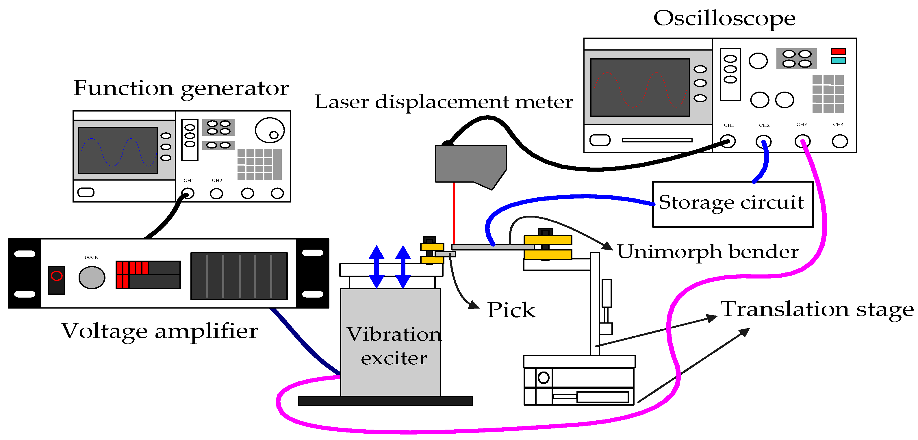
In order to observe the harvesting behavior of free-vibration, a measurement structure of the cantilever piezoelectric harvester is built as shown in Figure 8. A vibration exciter is utilized to simulate the low-frequency ambient environment, and its vibration frequency can be controlled and driven by the function generator and the voltage amplifier. In order to provide an initial displacement, a pick component is designed to pluck the cantilever beam to generate a vibration, and located on the vibration exciter. In this paper, an initial displacement of the cantilever beam is utilized to excite a free vibration with the structure resonance frequency. Therefore, the testing piezoelectric harvester for a unimorph plate is fixed on a translation stage, and the plucking position can be adjusted to determine the initial displacement. Moreover, a laser displacement meter is used to measure the vibration amplitude and frequency on the surface of the cantilever beam, and the measuring data can be recorded in an oscilloscope. Finally, the harvesting energy will be stored in the designed storage circuit which includes a bridge rectifier circuit and a storage capacitance as shown in Figure 7, and its storage information is also recorded in the oscilloscope.
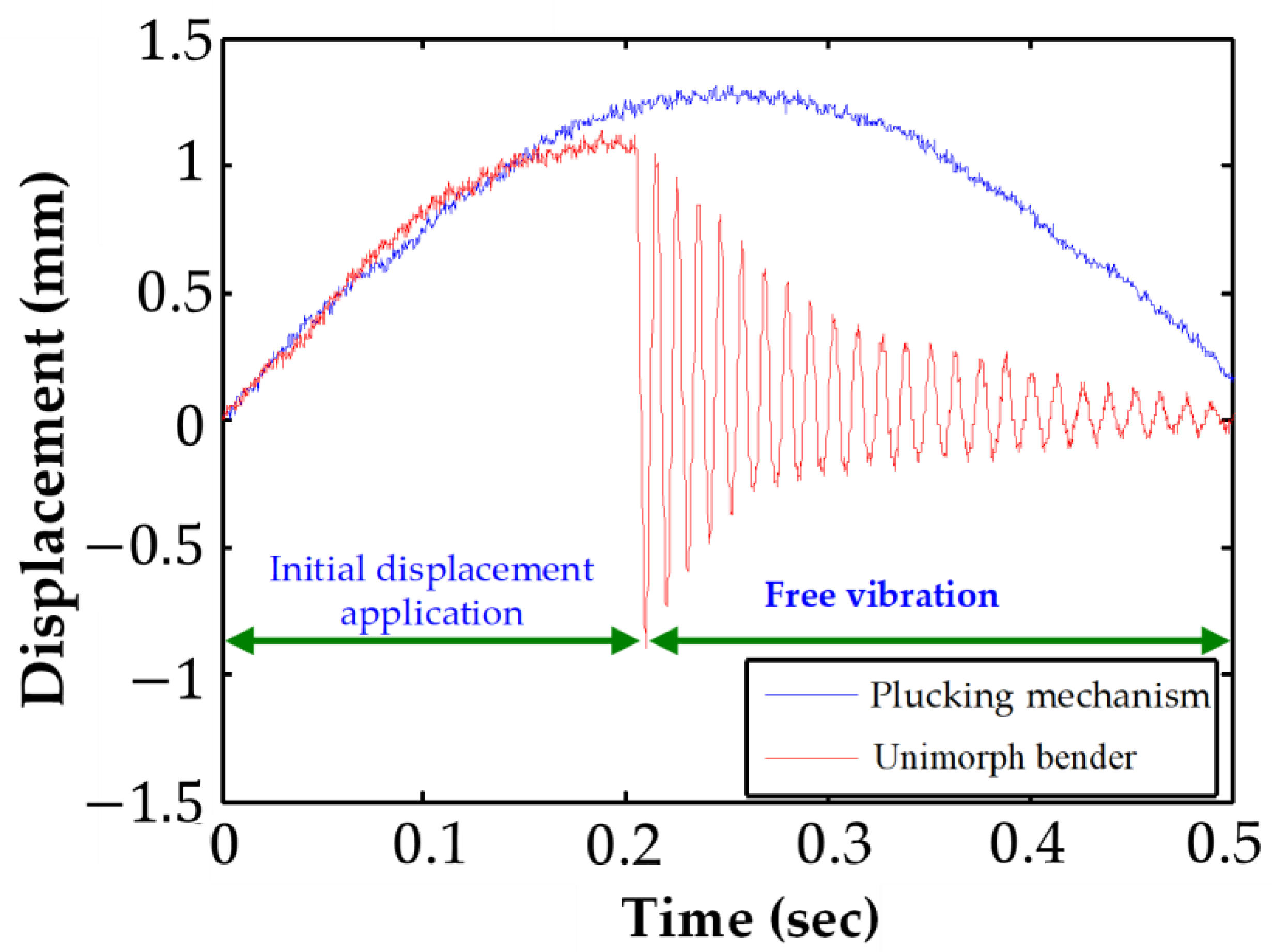
Figure 9 shows the measuring result of the vibration situation on the designed cantilever harvest and the pick of plucking mechanism. To simulate the walking of a human, the oscillating frequency of vibration exciter is controlled around 2 Hz of low frequency and 1.3 mm of vibration amplitude. By the translation stage adjustment, the pick can produce around 1 mm of the initial deformed displacement on the front end of the unimorph plate. Observing Figure 9, at first, the pick presses the unimorph plate to result in a deformation. When the pick holding position is over the setting deformed displacement, the unimorph plate will be released suddenly and excited a free vibration with its resonance frequency on free end. The free vibration will be reduced by its internal capacitor characteristic (Cp) based on the equivalent circuit, and the decay coefficient can be estimated as system equivalent damping factor ( ξ ) of Equation (17). Therefore, according to measuring result of vibration form, the structure resonance frequency ( f n ) and the decay coefficient ( ξ ) are estimated to be around 125 Hz and 0.0089 N Δ s m , respectively. These calculated data can be combined with the dimensions and material parameters of the proposed unimorph plate, as listed in Table 2. The electric generating characteristic of the designed piezoelectric harvester can be estimated, and utilized to analyze the electrical charging behaviors for the connecting storage circuit of capacitor by circuit simulation software.
Because the output energy of the general piezoelectric harvester is not enough to drive the electric component during a period of vibration loading, the storage circuit should be designed to receive and charge to obtain the sufficient driven energy. Moreover, due to the electrical generating characteristics of high voltage and low current, a capacitor is generally chosen to charge the out voltage from a piezoelectric harvester. Therefore, the driven power can be estimated from the voltage variation in the charging capacitor, and the relationship is presented as:
E C = 1 2 C L V C 2
where E C means the storage energy in the capacitor according to variation of the charging voltage ( V C ).
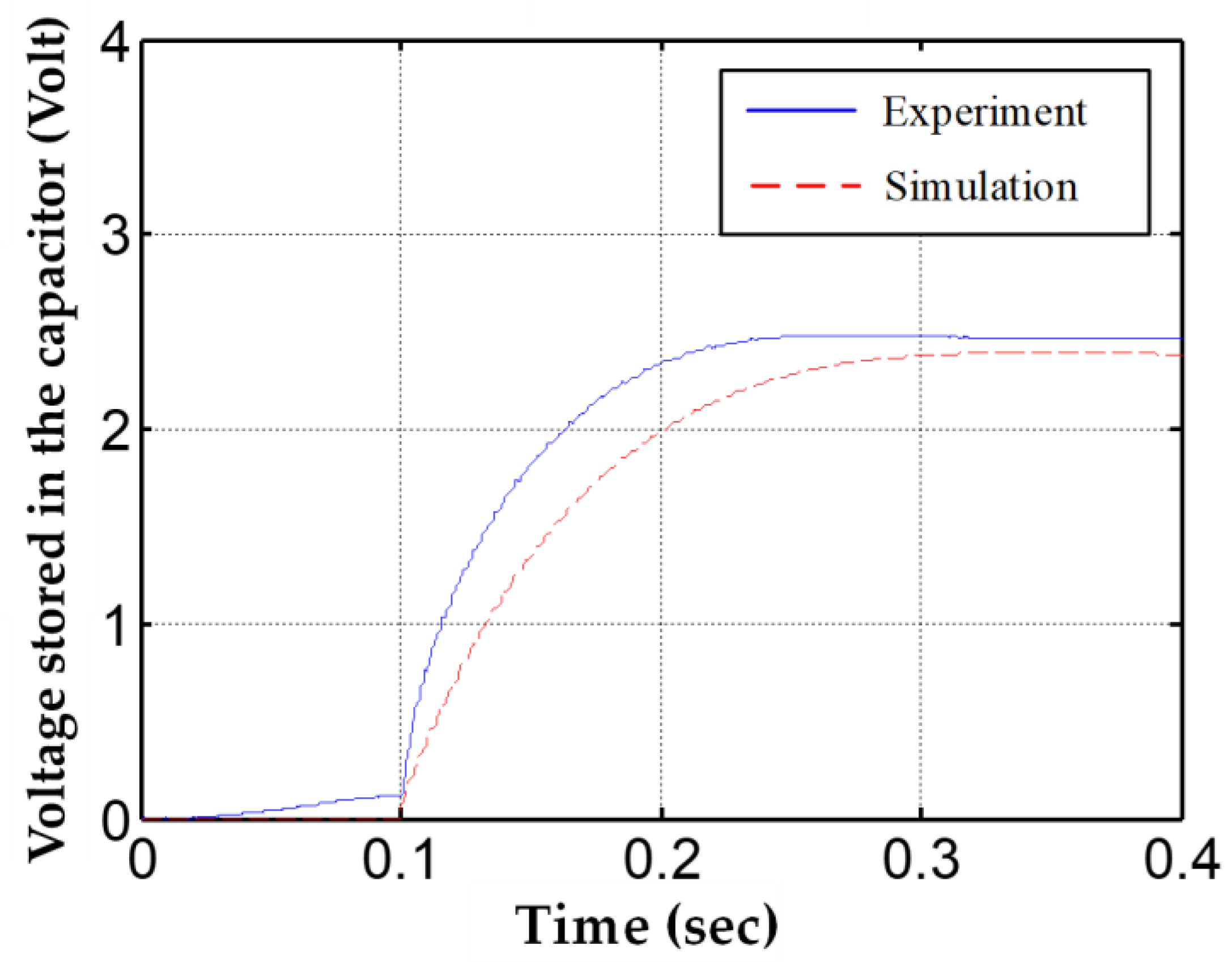
Therefore, in this paper, a 33 μF of capacitor was chosen to observe the charging voltage for the one-time plucking process, as shown in Figure 10. It can be observed that the voltage charging in a 33 μF capacitor was increased to around 2.45 Volt for the one-time plucking process, and the charging energy can be calculated as 0.101 mJ by Equation (25). Moreover, according to the designed parameters in Table 2, the charging situation of the capacitor can also be simulated by the circuit simulation software and the proposed theoretical model, as demonstrated by the red dashed-line in Figure 8. From the simulation result, a 2.37 Volt storage voltage can be observed for a 33 μF capacitor, which is equaled to the charging energy as 0.093 mJ by Equation (25). The experiment data appeared as a storage energy generation in the first pressing process from the pick results in a 0.1 Volt of initial storage voltage before the free vibration process. This initial storage voltage is ignored in simulation and caused an 8% error occurrence for storage energy with stable state. From the comparison result, it demonstrates a potential achievement that the output voltage and energy charging behaviors in an external capacitor can be predicted by the proposed theoretical model, and utilized to evaluate the driven capability for the electrical loading.

4. Design and Testing of Piezoelectric Harvesting Floor

Figure 11 demonstrates the designed piezoelectric harvesting floor. A piezoelectric unimorph plate is fixed to be a cantilever beam structure, and a pick is located towards the front of the unimorph plate to pluck an initial deformed displacement. The four pillars of the machine limit the floor with only vertical motion, and adjust the transformed space of the harvesting floor. When human steps on the floor, a vertical movement occurred to drive the pick to generate a plucking motion, which is equaled to an impact force to cause the resonant vibration occurrence. When human leaves the harvesting floor, springs on the four pillars are utilized to rebound the floor surface back to its original height and provide a second plucking process. During the free vibration procedure, the piezoelectric beam will transform to output electricity by electro-mechanical converted characteristic. Moreover, a storage circuit, consisting of a bridge rectifier circuit and charging capacitor, is used to receive the harvesting energy from the piezoelectric unimorph plate. During one-time footstep motion, the storage capacitor can charge a sufficient energy to drive the wireless transmitter module, and then send an RF signal to remote the working switch.
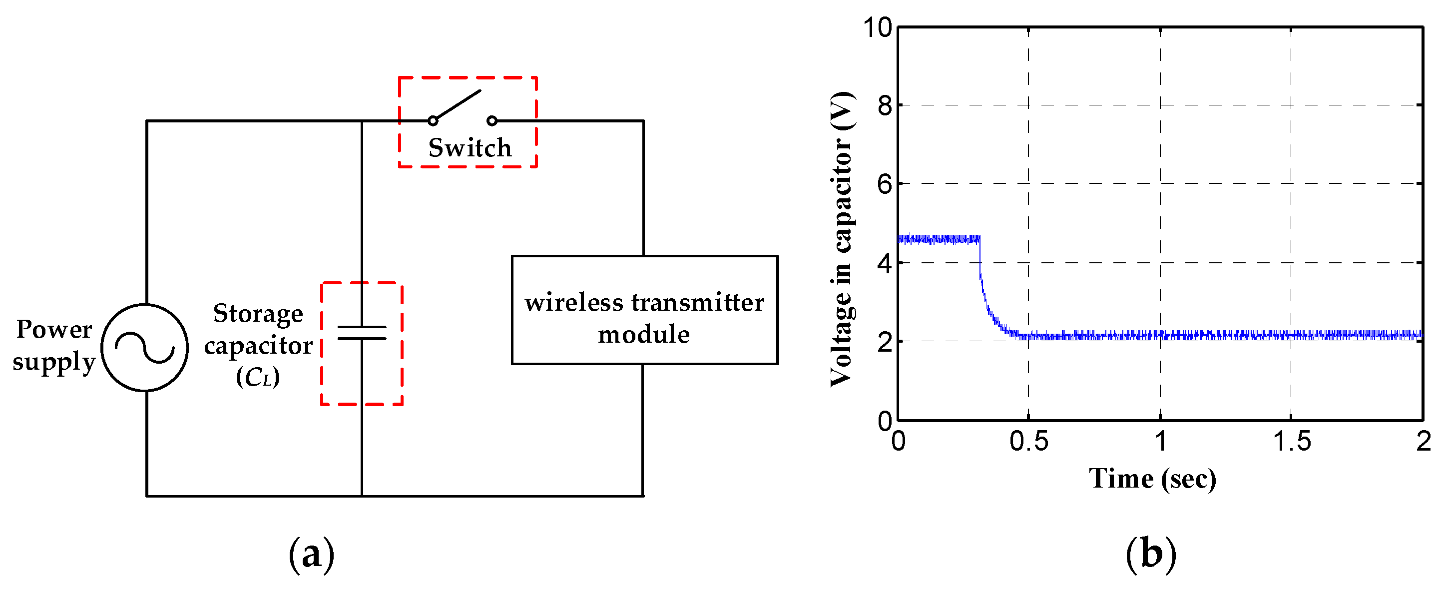
In the designed piezoelectric harvesting floor, the harvesting energy from one-time footstep motion should be sufficient to drive the wireless transmitter module. Therefore, the driven energy for sending an RF signal is necessary for determination, and the measuring experiment is shown in Figure 12. According to the testing circuit in Figure 12a, a power supply is used to charge a capacitor at first. When the charging process is completed, the switch will start to drive the wireless transmitter module, and the voltage variation in the storage capacitor can be measured to estimate the sufficient driven power. From the measuring result of Figure 12b, a 33 μF of storage capacitor is chosen and it can be observed that a 4.6 Volt of full charge voltage is suddenly reduced to 2.2 Volt. Therefore, based on Equation (25), a 0.269 mJ of driven power can be calculated for the wireless signal transmission.
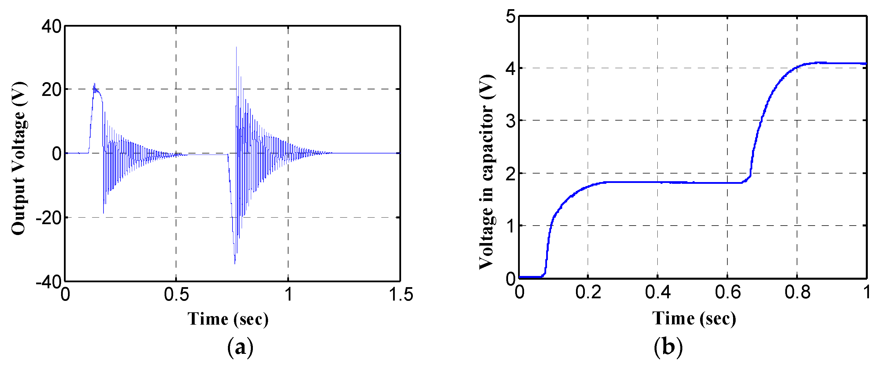
Finally, the harvesting behaviors of the designed piezoelectric floor are measured actually, as shown in Figure 13. From the output voltage, it can be found that the standing–up and leaving motion can excite the resonant vibration of the cantilever piezoelectric plate, respectively, and both of the frequency is the same with its structure resonant frequency of about 125 Hz. Moreover, the voltage charging in the storage capacitor can be increased into 4.1 Volt during two times of the resonant vibration procedure, and the charging can be calculated around 0.278 mJ which is larger than the driven power of the wireless transmitter module. Therefore, from the measuring result, it demonstrates a potential capacity that the designed piezoelectric harvesting floor can transfer human walking energy into the electric driven voltage, and transmitting a wireless RF signal can be achieved without external power supply.

5. Discussion

This paper demonstrated a significant piezoelectric harvesting method, by quickly releasing an initial deformed displacement of the cantilever beam, an equivalent impact force can be produced to cause the blender to excite a free vibration with the structure resonance frequency, and the electro-mechanical converted efficiency can be improved at low-frequency environment. To analyze the harvesting behaviors, an equivalent circuit of the theoretical model is provided, and the power of voltage source can be varied by the initial deformed displacement. Additionally, the storage situation of external capacitance can be analyzed by circuit simulation software. From the comparison of measurement and simulation, it reveals a significant efficiency of the theoretical model that 8% error occurrence for storage energy was found. To develop the proposed free-vibration type of electric generation method, a piezoelectric harvesting floor is designed and a low frequency of human walking motion can be transferred into the electric energy, and a wireless transmitter can be driven to send a RF signal without external power supply. Therefore, the designed piezoelectric harvesting floor can be utilized to locate the user’s current position, which provides users with the potentials for the intelligent building application. Moreover, the proposed piezoelectric harvesting method is free from the effects of the external environment, and provides the best electro-mechanical conversion efficiency. It can further be extensively utilized in daily harvesting applications, such as walking energy, ocean/river wave, and windmill rotation.

6. Conclusions

In this paper, in order to improve the electro-mechanical converted efficiency of a piezoelectric cantilever harvester at a low-frequency environment, a free vibration with the structure resonant frequency excited by releasing an initial deformed displacement was proposed to obtain best harvesting efficiency, and its theoretical model of an equivalent circuit was built to analyze the harvesting behaviors. From the compared result, an 8% error of storage energy in the external capacitor during one-time free resonant vibration generation was found between the measurement and simulation. Therefore, according to a significant revealing efficiency of the theoretical model, a piezoelectric harvesting floor can be designed to transfer the human walking energy into electric power. Depending on the driven condition of a wireless RF signal, the dimensions of the piezoelectric cantilever beam and the initial exciting displacement can be determined. The testing result presented that the one-time footstep motion can harvest the electric energy twice, and cause a 0.278 mJ charging energy in a 33 μF of storage capacitor, which was sufficient to drive the wireless transmitter. Therefore, the designed piezoelectric harvesting floor demonstrated a potential intelligent building application that can detect human walking motion, and transmit a wireless RF signal for the future appropriate service without external power supply.

Author Contributions

Conceptualization, S.-H.W. and T.-H.W.; methodology, T.-H.W.; software, T.-H.W.; validation, S.-H.W., and M.-C.T.; formal analysis, S.-H.W.; investigation, S.-H.W.; data curation, T.-H.W.; writing—original draft preparation, T.-H.W.; writing—review and editing, M.-C.T.; visualization, S.-H.W.; supervision, M.-C.T.; project administration, S.-H.W.; funding acquisition, M.-C.T. All authors have read and agreed to the published version of the manuscript.

Funding

This research was funded by the Ministry of Science and Technology, Taiwan, under Grant no. MOST 109-2221-E-218-017.

Institutional Review Board Statement

Not applicable.

Informed Consent Statement

Informed consent was obtained from all subjects involved in the study.

Data Availability Statement

The content presented here was sourced from existing published literature, hence, this clause is not applicable.

Acknowledgments

The authors acknowledge the Electric Motor Technology Research Center at National Cheng Kung University in Tainan, Ministry of Science and Technology (MOST) for their financial support for the research work reported in this article.

Conflicts of Interest

The authors declare no conflict of interest.

References

  1. Lazaro, A.; Villarino, R.; Girbau, D. A Survey of NFC Sensors Based on Energy Harvesting for IoT Applications. Sensors 2018, 18, 3746. [Google Scholar] [CrossRef] [PubMed] [Green Version]
  2. Vullers, R.; van Schaijk, R.; Doms, I.; Van Hoof, C.; Mertens, R. Micropower energy harvesting. Solid State Electron. 2009, 53, 684–693. [Google Scholar] [CrossRef]
  3. Mitcheson, P.; Miao, P.; Stark, B.; Yeatman, E.; Holmes, A.; Green, T. MEMS electrostatic micropower generator for low frequency operation. Sens. Actuators A Phys. 2004, 115, 523–529. [Google Scholar] [CrossRef] [Green Version]
  4. Glynne-Jones, P.; Tudor, M.; Beeby, S.; White, N. An electromagnetic, vibration-powered generator for intelligent sensor systems. Sens. Actuators A Phys. 2004, 110, 344–349. [Google Scholar] [CrossRef] [Green Version]
  5. Jintanawan, T.; Phanomchoeng, G.; Suwankawin, S.; Kreepoke, P.; Chetchatree, P. Design of Kinetic-Energy Harvesting Floors. Energies 2020, 13, 5419. [Google Scholar] [CrossRef]
  6. Elahi, H.; Eugeni, M.; Gaudenzi, P. A Review on Mechanisms for Piezoelectric-Based Energy Harvesters. Energies 2018, 11, 1850. [Google Scholar] [CrossRef] [Green Version]
  7. Rastegar, J.; Pereira, C.; Nguyen, H.-L. Piezoelectric-based power sources for harvesting energy from platforms with low-frequency vibration. In Proceedings of the SPIE Smart Structures and Materials + Nondestructive Evaluation and Health Monitoring, San Diego, CA, USA, 26 February–2 March 2006. [Google Scholar] [CrossRef]
  8. Erturk, A.; Inman, D.J. A distributed parameter electromechanical model for cantilevered piezoelectric energy harvesters. J. Vib. Acoust. 2008, 130, 041002. [Google Scholar] [CrossRef]
  9. Cornwell, P.J.; Goethal, J.; Kowko, J.; Damianakis, M. Enhancing Power Harvesting Using a Tuned Auxiliary Structure. J. Intell. Mater. Syst. Struct. 2005, 16, 825–834. [Google Scholar] [CrossRef]
  10. Shahruz, S. Design of mechanical band-pass filters for energy scavenging. J. Sound Vib. 2006, 292, 987–998. [Google Scholar] [CrossRef]
  11. Umeda, M.; Nakamura, K.; Ueha, S. Analysis of the Transformation of Mechanical Impact Energy to Electric Energy Using Piezoelectric Vibrator. Jpn. J. Appl. Phys. 1996, 35, 3267–3273. [Google Scholar] [CrossRef]
  12. Fu, H.; Yeatman, E.M. Effective piezoelectric energy harvesting using beam plucking and a synchronized switch harvesting circuit. Smart Mater. Struct. 2018, 27, 084003. [Google Scholar] [CrossRef] [Green Version]
  13. Tang, Q.C.; Yang, Y.L.; Li, X. Bi-stable frequency up-conversion piezoelectric energy harvester driven by non-contact magnetic repulsion. Smart Mater. Struct. 2011, 20, 125011. [Google Scholar] [CrossRef]
  14. Xue, T.; Roundy, S. Analysis of Magnetic Plucking Configurations for Frequency Up-Converting Harvesters. J. Phys. Conf. Ser. 2015, 660, 012098. [Google Scholar] [CrossRef]
  15. Lei, G.; Carol, L. Impact-driven, frequency up-converting coupled vibration energy harvesting device for low frequency operation. Smart Mater. Struct. 2011, 20, 045004. [Google Scholar]
  16. Jacquelin, E.; Adhikari, S.; Friswell, M.I. A piezoelectric device for impact energy harvesting. Smart Mater. Struct. 2011, 20, 105008. [Google Scholar] [CrossRef]
  17. Pozzi, M.; Aung, M.S.; Zhu, M.; Jones, R.K.; Goulermas, J.Y. The pizzicatoknee-joint energy harvester: Characterization with biomechanical data and the effect of backpack load. Smart Mater. Struct. 2012, 21, 075023. [Google Scholar] [CrossRef]
  18. Abdal, M.; Leong, K.S. Piezoelectric Pre-Stressed Bending Mechanism for Impact Driven Energy Harvester. Int. Tech. Postgrad. Conf. Ser. Mater. Sci. Eng. 2017, 210, 012037. [Google Scholar] [CrossRef]
  19. Pozzi, M. Impulse excitation of piezoelectric bimorphs for energy harvesting: A dimensionless model. Smart Mater. Struct. 2014, 23, 045044. [Google Scholar] [CrossRef] [Green Version]
  20. Pillatsch, P.; Yeatman, E.M.; Holmes, A.S. Magnetic plucking of piezoelectric beams for frequency up-converting energy harvesters. Smart Mater. Struct. 2014, 23, 025009. [Google Scholar] [CrossRef]
  21. Kuang, Y.; Zhu, M. Design study of a mechanically plucked piezoelectric energy harvester using validated finite element modelling. Sens. Actuators A Phys. 2017, 263, 510–520. [Google Scholar] [CrossRef]
  22. Jivkov, V.; Zahariev, E. Cantilever Beam Natural Frequencies in Centrifugal Inertia Field. J. Theor. Appl. Mech. 2018, 48, 37–45. [Google Scholar] [CrossRef]
  23. Özer, A. Özkan Dynamic and electrostatic modeling for a piezoelectric smart composite and related stabilization results. Evol. Equ. Control Theory 2018, 7, 639–668. [Google Scholar] [CrossRef] [Green Version]
  24. Erturk, A.; Inman, D.J. An experimentally validated bimorph cantilever model for piezoelectric energy harvesting from base excitations. Smart Mater. Struct. 2009, 18, 025009. [Google Scholar] [CrossRef]
  25. Lin, J.H. A Study of Rubber Admixture in Concrete on Damping Ratio Property. Master’s Thesis, Architecture, National Cheng Kung University, Tainan, Taiwan, 2007. [Google Scholar]
  26. Rao, S.S. Mechanical Vibrations, 4th ed.; Pearson Prentice Hall: Upper Saddle River, NJ, USA, 2004; pp. 154–196. [Google Scholar]
  27. Wang, S.-H.; Tsai, M.-C. Dynamic modeling of thickness-mode piezoelectric transducer using the block diagram approach. Ultrasonics 2011, 51, 617–624. [Google Scholar] [CrossRef] [PubMed]
  28. Raslan, K.R.; Biswas, A.; Zaim, F.; Sheer, A. Differential Transform Method for Solving Partial Differential Equations with Variable Coefficients. Int. J. Phys. Sci. 2012, 7, 1412–1419. [Google Scholar] [CrossRef] [Green Version]
  29. Gere, J.M. Mechanics of Materials, 6th ed.; Thomson-Engineering: Denver, CO, USA, 2003; pp. 330–340. [Google Scholar]
  30. Korshunov, V.; Volobuev, P.S. Exploring of equivalent circuit model of piezoelectric energy harvesters for ultra low-power devices. In Proceedings of the 2015 IEEE East-West Design & Test Symposium (EWDTS), Batumi, Georgia, 26–29 September 2015; pp. 1–4. [Google Scholar] [CrossRef]
  31. Ikeda, T. Fundamentals of Piezoelectricity; Oxford University Press: Oxford, UK, 1990; pp. 4–8. [Google Scholar]
  32. Chen, D.K. Field and Wave Electromagnetics, 2nd ed.; Addison-Wesley: Boston, MA, USA, 1989; pp. 43–50. [Google Scholar]
  33. Yang, Y.; Shi, X.; Lan, H.; Xiao, Z.; Dong, Y.; Liu, Y.; Yang, T. Investigation on behavior of the vibration-based piezoelectric energy harvester array in ultracapacitor charging. Appl. Phys. Lett. 2015, 106, 173902. [Google Scholar] [CrossRef]
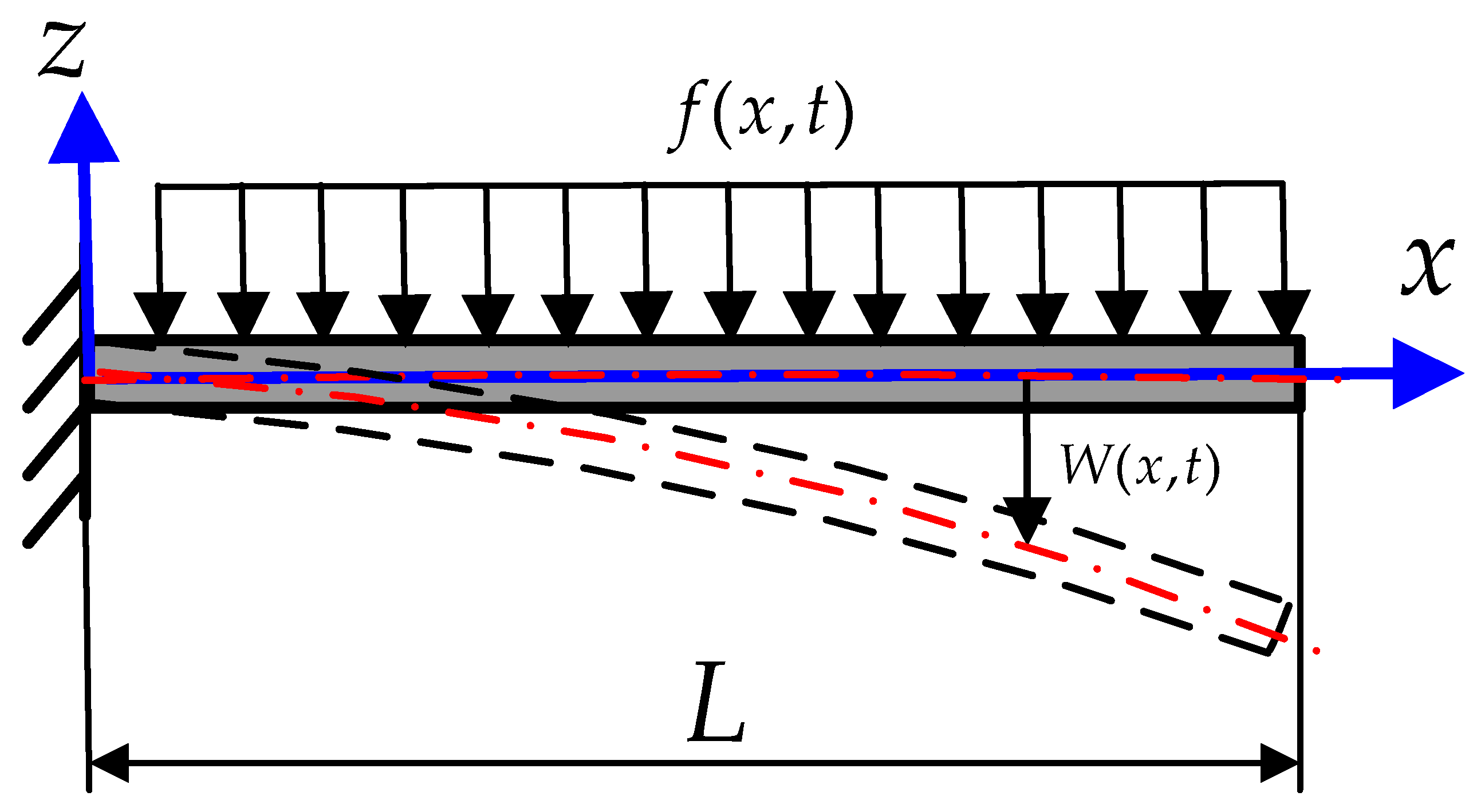
Figure 1. Mathematical schematic of Euler–Bernoulli cantilever beam structure [22].
Crystals 11 00380 g001
Figure 2. Equivalent mechanical model to describe relationship between external force and deformed displacement [25,27].
Crystals 11 00380 g002
Figure 3. Theoretical model of piezoelectric cantilever beam structure, which is separated into three sections.
Crystals 11 00380 g003
Figure 4. Cross sectional area transformation in composite unimorph section: (a) In original, cross sectional area is the same; (b) width of piezoelectric plate is varied to be equaled to the same material depend on the modular ratio of different Young’s modulus.
Crystals 11 00380 g004
Figure 5. Complete equivalent circuit of piezoelectric cantilever beam structure converted from its electromechanical model [30].
Crystals 11 00380 g005
Figure 6. Simplified piezoelectric equivalent circuit form; (a) Current source type of Norton’s equivalent circuit; (b) Voltage source type of Thevenin’s equivalent circuit [33].
Crystals 11 00380 g006
Figure 7. Theoretical electric circuit of proposed piezoelectric harvesting system.
Crystals 11 00380 g007
Figure 8. Experiment structure of cantilever harvester with free vibration to measure electric power generation and vibration situation.
Crystals 11 00380 g008
Figure 9. Measured results of vibration amplitude on front end of cantilever beam and motion trajectory of plucking mechanism.
Crystals 11 00380 g009
Figure 10. Measured data of voltage charge in capacitor and compared with simulation result.
Crystals 11 00380 g010
Figure 11. Structure of designed piezoelectric harvesting floor, which consists of a piezoelectric unimorph plate, a plucking mechanism, a storage circuit, and the driven wireless transmitter module.
Crystals 11 00380 g011
Figure 12. Measurement of driven condition for wireless transmitter module; (a) Designed testing electric circuit to obtain driven power and storage capacitor determination; (b) Testing result of voltage variation in storage capacitor.
Crystals 11 00380 g012
Figure 13. Measurement result of electric generation from the designed piezoelectric harvesting floor, which includes; (a) Voltage output from piezoelectric unimorph plate; (b) Voltage charging situation in storage capacitor.
Crystals 11 00380 g013
Table 1. Calculated result of ratio coefficient in Equation (10).
Ratio
Coefficient
ValueRatio
Coefficient
Value
a00b2 F ( L b + 2 L c ) 4 E b I b
a10b3 F 6 E c I c
a2 F ( L a + L b + 2 L c ) 4 E a I a c0 F [ L a 12 E a I a ( L a 2 + 3 L a L b + 6 L a L c + 12 L b L c + 6 L b 2 ) + 1 12 E b I b ( L b 3 + 6 L b 2 L c ) ]
a3 F 6 E a I a c1 F [ 1 2 E a I a ( L a L b + 2 L a L c ) + 1 E b I b ( L b L c ) ]
b0 F ( L a 3 + 3 L a 2 L b + 6 L a 2 L c ) 12 E a I a c2 3 F L c 6 E c I c
b1 F ( L a L b + 2 L a L c ) 2 E a I a c3 F 6 E c I c
Table 2. Dimension and parameters of proposed piezoelectric unimorph plate to be utilized in electric power calculation by theoretical equivalent circuit.
Piezoelectric PlateSteel Plate
materialPZT-5Hmaterial SAE 304
Length (Lb)30 mmLength (L)58 mm
Width (b)15 mmWidth (b)15 mm
Thickness (tp)0.3 mmThickness (ts)0.3 mm
Young’s modulus (Ep) 127.2 × 10 9 N m 2 Young’s modulus (Es) 200 × 10 9 N m 2
Piezoelectric charge constant (d31) 274 × 10 12   C N Length of section A (La)5 mm
Permittivity coefficient ( ε 33 T )3400 ε 0 Length of section C (Lc)23 mm
Permittivity in vacuum ( ε 0 ) 8.854 × 10 12 F m Initial deformation ( Δ 0 )1 mm
Publisher’s Note: MDPI stays neutral with regard to jurisdictional claims in published maps and institutional affiliations.